CN212160974U - Computer-aided education teaching equipment - Google Patents
Computer-aided education teaching equipment Download PDFInfo
- Publication number
- CN212160974U CN212160974U CN202021326783.XU CN202021326783U CN212160974U CN 212160974 U CN212160974 U CN 212160974U CN 202021326783 U CN202021326783 U CN 202021326783U CN 212160974 U CN212160974 U CN 212160974U
- Authority
- CN
- China
- Prior art keywords
- fixed
- plate
- rotating shaft
- computer
- channel
- Prior art date
- Legal status (The legal status is an assumption and is not a legal conclusion. Google has not performed a legal analysis and makes no representation as to the accuracy of the status listed.)
- Expired - Fee Related
Links
Images


Abstract
The utility model discloses a computer-aided education teaching device, which belongs to the technical field of computer education, and comprises a base, the upper surface of the base is fixed with a fixed cylinder, the top of the fixed cylinder is provided with a supporting plate, the inside of the fixed cylinder is provided with a driving part, the upper surface of the supporting plate is provided with a U-shaped mounting seat and a placing plate, the inside of the U-shaped mounting seat is hinged with a mounting plate through a first pin shaft, a display screen is fixed on the mounting plate, the inside of the supporting plate is provided with a cavity and a first channel which are communicated with each other, a screw rod is installed in the internal rotating shaft of the cavity, and a second rotating shaft is fixed at one end of; through setting up drive assembly, utilize the motor to drive pivot one and rotate to roll in the ring channel of universal ball on the supporting seat of cooperation and support the backup pad, and then make the backup pad can rotate, realize that the display screen in the backup pad rotates, satisfy the student of different positions department and look over, simple structure, convenient operation.
Description
Technical Field
The utility model belongs to the technical field of computer education, concretely relates to computer-aided education teaching equipment.
Background
Traditional education mode is that the mr utilizes the blackboard to express and write class, now along with the development of society, the computer has become the indispensable use tool in the middle of people's life, the teaching course of using the computer has been carried out in more and more institute's school of higher school, computer-aided education teaching equipment is an auxiliary computer and improves computer teaching quality greatly, computer-aided education teaching equipment simple structure, high convenience of operation, utilize the computer to make teaching course and come out through the display screen projection and supply the student to look over, make the mr not need to write at the letter always on the blackboard.
The angle of the display screen of the existing computer-aided education teaching equipment in the use process cannot be adjusted according to teaching needs, and cannot be adjusted in a rotating mode, so that certain inconvenience exists in the use process.
SUMMERY OF THE UTILITY MODEL
An object of the utility model is to provide a computer-aided education teaching equipment drives the backup pad through being provided with the drive division and rotates to utilize screw rod normal running fit switching part to adjust the mounting panel angle, can not adjust according to the teaching needs with the angle of solving the current computer-aided education teaching equipment that proposes in the above-mentioned background art display screen in the use, and can not rotate the regulation, have certain inconvenient problem in the use.
In order to achieve the above object, the utility model provides a following technical scheme: the utility model provides a computer-aided education teaching equipment, includes the base, the last fixed surface of base has a fixed section of thick bamboo, the top of a fixed section of thick bamboo is provided with the backup pad, the internally mounted of a fixed section of thick bamboo has the drive division, the last surface mounting of backup pad has the U-shaped mount pad and places the board, the inside of U-shaped mount pad articulates through round pin axle one has the mounting panel, be fixed with the display screen on the mounting panel, cavity and passageway one that is linked together are seted up to the inside of backup pad, the screw rod is installed in the inside pivot of cavity, the one end at the screw rod back is fixed with pivot two, the pivot two be located passageway one inside and with the passageway in the bearing two rotate between the joint be connected, install the handle on the pivot two, the surface thread mounting of screw rod has the fly leaf, install switching portion.
Adopt above-mentioned scheme, through setting up drive assembly, utilize the motor to drive a pivot rotation, and roll in the ring channel of cooperation universal ball on the supporting seat and support the backup pad, and then make the backup pad can rotate, thereby realize that the display screen in the backup pad rotates, satisfy the student of different positions department and look over, moreover, the steam generator is simple in structure, high durability and convenient operation, through setting up screw rod and switching part, the rotation that utilizes the screw rod drives the fly leaf seesaw, and utilize articulated effect between connecting rod and fixed block and the fly leaf to make the mounting panel can rotate around a round pin axle one place axis, and then realize the angle modulation of display screen on the mounting panel, satisfy actual teaching needs, therefore, the high-.
In the above scheme, it should be noted that the motor is electrically connected to an external power supply.
As a preferred embodiment, the driving part comprises a motor and a first rotating shaft, the motor is installed inside the first fixing cylinder, an output shaft of the motor is fixedly connected with the bottom end of the first rotating shaft, the first rotating shaft is rotatably connected with the first fixing cylinder, and the top end of the first rotating shaft is fixedly connected with the lower surface of the supporting plate.
Adopt above-mentioned scheme, drive pivot one through installing the motor and rotate, and then drive the backup pad through pivot one and rotate to realize that the display screen in the backup pad rotates, reach the rotation regulation of display screen, satisfy the student of different positions and look over, simple structure, extensive applicability.
As a preferred embodiment, the switching part comprises a connecting rod and a fixed block, one end of the connecting rod is hinged to the fixed block through a second pin shaft, the fixed block is mounted on the mounting plate, and one end of the connecting rod, far away from the fixed block, penetrates through a second channel formed in the upper surface of the support plate, extends into the cavity and is hinged to the movable plate through a third pin shaft.
By adopting the scheme, the connecting rod and the fixed block are installed, when the movable plate is driven to move back and forth in the screw rotation process, the mounting plate can rotate through the first pin shaft by utilizing the hinging effect among the movable plate, the connecting rod and the fixed block, so that the angle adjustment of the display screen on the mounting plate is realized, and the actual teaching requirement is met.
As a preferred embodiment, the left and right sides face of the movable plate is provided with a guide block, the guide block is slidably connected to the outer surface of the guide rod, and two ends of the guide rod are fixedly connected with the front and rear sides of the inner side wall of the cavity respectively.
By adopting the scheme, the guide block is installed, the guide block can be driven to synchronously slide on the surface of the guide rod in the process that the screw rotates to drive the movable plate to move forwards and backwards, and the movable plate is limited and supported by the aid of the guide rod and the guide block, so that the movable plate cannot rotate in the process of moving forwards and backwards and is good in movement stability.
As a preferred embodiment, the upper surface mounting of base has the supporting seat, the through-hole has been seted up on the supporting seat, fixed section of thick bamboo is located the inside of through-hole, the lower surface of backup pad is annular array and installs a plurality of universal ball, universal ball roll connection is at the inside wall of ring channel, the upper surface at the supporting seat is seted up to the ring channel.
Adopt above-mentioned scheme, through installing the supporting seat, can drive universal ball and slide in the ring channel at the backup pad rotation in-process, and then utilize universal ball to support the backup pad at slide fit supporting seat in the universal city for the backup pad can not take place to rock and more stable rotating the in-process.
In a preferred embodiment, the front, rear, and left and right side surfaces of the support base are provided with receiving grooves.
Adopt above-mentioned scheme, through having seted up on the supporting seat and accomodate the groove, put into to accomodate the inslot with the teaching tool at mr's teaching and education in-process and accomodate convenient to use.
Compared with the prior art, the beneficial effects of the utility model are that:
the computer-aided education teaching equipment is provided with the driving assembly, the motor is used for driving the rotating shaft to rotate, and the universal ball is matched with the annular groove in the supporting seat to roll to support the supporting plate, so that the supporting plate can rotate, the display screen on the supporting plate can rotate, the requirements of viewing by students at different positions are met, and the computer-aided education teaching equipment is simple in structure and convenient to operate;
this computer-aided education teaching equipment utilizes the rotation of screw rod to drive fly leaf seesaw through setting up screw rod and switching part to utilize the articulated effect between connecting rod and fixed block and the fly leaf to make the mounting panel can rotate around round pin axle one place axis, and then realize the angle modulation of display screen on the mounting panel, satisfy actual teaching needs, extensive applicability.
Drawings
Fig. 1 is a schematic structural view of the present invention;
FIG. 2 is a schematic structural view of a front view section of the present invention;
FIG. 3 is a schematic structural view of the support plate of the present invention in a top-down half-section view;
FIG. 4 is a schematic structural view of a right-side cross section of the support plate of the present invention;
fig. 5 is an enlarged schematic structural view of a point a in fig. 2 according to the present invention.
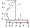
In the figure: 1. a base; 2. a fixed cylinder; 3. a motor; 4. a first rotating shaft; 5. a support plate; 6. a U-shaped mounting seat; 7. placing the plate; 8. mounting a plate; 9. a display screen; 10. a cavity; 11. a first channel; 12. a screw; 13. a second rotating shaft; 14. a handle; 15. a movable plate; 16. a connecting rod; 17. a second channel; 18. a fixed block; 19. a guide block; 20. a guide bar; 21. a universal ball; 22. an annular groove; 23. a receiving groove; 24. and (4) supporting the base.
Detailed Description
The present invention will be further described with reference to the following examples.
The following examples are intended to illustrate the invention, but are not intended to limit the scope of the invention. The condition in the embodiment can be further adjusted according to concrete condition the utility model discloses a it is right under the design prerequisite the utility model discloses a simple improvement of method all belongs to the utility model discloses the scope of claiming.
Referring to fig. 1-5, the utility model provides a computer-aided education teaching device, which comprises a base 1, wherein a supporting seat 24 is installed on the upper surface of the base 1, a through hole is opened on the supporting seat 24, a fixed cylinder 2 is positioned inside the through hole, a plurality of universal balls 21 are installed on the lower surface of a supporting plate 5 in an annular array, the universal balls 21 are connected with the inner side wall of an annular groove 22 in a rolling manner, and the annular groove 22 is opened on the upper surface of the supporting seat 24 (see fig. 2); through installing supporting seat 24, can drive universal ball 21 and slide in ring channel 22 at backup pad 5 rotation in-process, and then utilize universal ball 21 to support backup pad 5 at slide fit supporting seat 24 in the universal city for backup pad 5 can not take place to rock and more stable rotating the in-process.
The front, back, front and rear side faces and the left and right side faces of the support seat 24 are provided with accommodating grooves 23 (see fig. 1 and 2); through having seted up on supporting seat 24 and accomodate groove 23, place into to accomodate groove 23 with the teaching tool at the mr in-process of educating the teaching and take in convenient to use.
A fixed cylinder 2 is fixed on the upper surface of the base 1, a supporting plate 5 is arranged above the fixed cylinder 2, a driving part is arranged inside the fixed cylinder 2, the driving part comprises a motor 3 and a rotating shaft I4, the motor 3 is arranged inside the fixed cylinder 2, an output shaft of the motor 3 is fixedly connected with the bottom end of the rotating shaft I4, the rotating shaft I4 is rotatably connected with the fixed cylinder 2, and the top end of the rotating shaft I4 is fixedly connected with the lower surface of the supporting plate 5 (see fig. 2); drive pivot 4 through installing motor 3 and rotate, and then drive backup pad 5 through pivot 4 and rotate to realize that display screen 9 on the backup pad 5 rotates, reach the rotation regulation of display screen 9, satisfy the student of different positions and look over, simple structure, extensive applicability.
A U-shaped mounting seat 6 and a placing plate 7 are mounted on the upper surface of a supporting plate 5, a mounting plate 8 is hinged inside the U-shaped mounting seat 6 through a first pin shaft, a display screen 9 is fixed on the mounting plate 8, a cavity 10 and a channel I11 which are communicated with each other are formed inside the supporting plate 5, a screw 12 is mounted on a rotating shaft inside the cavity 10, a rotating shaft II 13 is fixed at one end of the back surface of the screw 12, the rotating shaft II 13 is located inside the channel I11 and is rotatably connected with a bearing II clamped in the channel I11, a handle 14 is mounted on the rotating shaft II 13, a movable plate 15 is mounted on the outer surface of the screw 12 through threads, guide blocks 19 are mounted on the left side surface and the right side surface of the movable plate 15, the guide blocks 19 are slidably connected to the outer surface of a guide rod 20, and two ends of the guide; by installing the guide block 19, the guide block 19 can be driven to synchronously slide on the surface of the guide rod 20 in the process that the screw 12 rotates to drive the movable plate 15 to move back and forth, and the guide rod 20 and the guide block 19 are matched to carry out limiting support on the movable plate 15, so that the movable plate 15 cannot rotate in the process of moving back and forth and has good motion stability.
A switching part is arranged between the movable plate 15 and the mounting plate 8, the switching part comprises a connecting rod 16 and a fixed block 18, one end of the connecting rod 16 is hinged with the fixed block 18 through a second pin shaft, the fixed block 18 is arranged on the mounting plate 8, and one end of the connecting rod 16, far away from the fixed block 18, penetrates through a second channel 17 formed in the upper surface of the support plate 5, extends into the cavity 10 and is hinged with the movable plate 15 through a third pin shaft (see fig. 2, 3, 4 and 5); by installing the connecting rod 16 and the fixed block 18, when the movable plate 15 is driven to move back and forth in the rotation process of the screw 12, the mounting plate 8 can rotate through the first pin shaft by utilizing the hinging action among the movable plate 15, the connecting rod 16 and the fixed block 18, so that the angle adjustment of the display screen 9 on the mounting plate 8 is realized, and the actual teaching requirement is met.
When the computer is used, a teacher places a computer on the placing plate 7 and connects the computer with the display screen 9, when the display screen 9 needs to be rotated, the control motor 3 is started, the motor 3 drives the first rotating shaft 4 to rotate, the first rotating shaft 4 drives the supporting plate 5 to rotate to realize the rotation of the display screen 9 on the supporting plate 5, when the angle of the display screen 9 needs to be adjusted, the rotating handle 14 drives the screw rod 12 to rotate through the second rotating shaft 13, the screw rod 12 rotates to drive the movable plate 15 to move forwards or backwards, and the connecting rod 16, the movable plate 15 and the fixed block 18 are hinged to enable the mounting plate 8 to rotate around the axis of the first pin shaft, so that the angle adjustment of the display screen 9 on the mounting plate 8 is realized, and teaching operation can be performed after the adjustment is completed.
Although embodiments of the present invention have been shown and described, it will be appreciated by those skilled in the art that changes, modifications, substitutions and alterations can be made in these embodiments without departing from the principles and spirit of the invention, the scope of which is defined in the appended claims and their equivalents.
Claims (6)
1. A computer-assisted education teaching apparatus characterized in that: comprises a base (1), a fixed cylinder (2) is fixed on the upper surface of the base (1), a supporting plate (5) is arranged above the fixed cylinder (2), a driving part is arranged inside the fixed cylinder (2), a U-shaped mounting seat (6) and a placing plate (7) are arranged on the upper surface of the supporting plate (5), a mounting plate (8) is hinged inside the U-shaped mounting seat (6) through a first pin shaft, a display screen (9) is fixed on the mounting plate (8), a cavity (10) and a first channel (11) which are communicated with each other are arranged inside the supporting plate (5), a screw rod (12) is arranged in an internal rotating shaft of the cavity (10), a second rotating shaft (13) is fixed at one end of the back of the screw rod (12), and the second rotating shaft (13) is positioned inside the first channel (11) and is rotationally connected with a second bearing which is clamped in the first channel (11), a handle (14) is installed on the second rotating shaft (13), a movable plate (15) is installed on the outer surface of the screw rod (12) in a threaded mode, and a switching portion is installed between the movable plate (15) and the installation plate (8).
2. The computer-assisted education teaching apparatus according to claim 1, wherein: the driving part comprises a motor (3) and a first rotating shaft (4), the motor (3) is installed inside the fixed cylinder (2), an output shaft of the motor (3) is fixedly connected with the bottom end of the first rotating shaft (4), the first rotating shaft (4) is rotatably connected with the fixed cylinder (2), and the top end of the first rotating shaft (4) is fixedly connected with the lower surface of the supporting plate (5).
3. The computer-assisted education teaching apparatus according to claim 1, wherein: the switching part comprises a connecting rod (16) and a fixed block (18), one end of the connecting rod (16) is hinged to the fixed block (18) through a second pin shaft, the fixed block (18) is installed on the installation plate (8), and one end, far away from the fixed block (18), of the connecting rod (16) penetrates through a second channel (17) formed in the upper surface of the support plate (5) to extend into the cavity (10) and is hinged to the movable plate (15) through a third pin shaft.
4. The computer-assisted education teaching apparatus according to claim 1, wherein: guide block (19) are all installed to the left and right sides face of fly leaf (15), guide block (19) sliding connection is in the surface of guide bar (20), the both ends of guide bar (20) respectively with the front and back both sides face fixed connection of cavity (10) inside wall.
5. The computer-assisted education teaching apparatus according to claim 1, wherein: the upper surface mounting of base (1) has supporting seat (24), the through-hole has been seted up on supporting seat (24), gu fixed section of thick bamboo (2) are located the inside of through-hole, the lower surface of backup pad (5) is annular array and installs a plurality of universal ball (21), universal ball (21) roll connection is at the inside wall of ring channel (22), the upper surface at supporting seat (24) is seted up in ring channel (22).
6. The computer-assisted education teaching apparatus according to claim 5, wherein: the front side surface, the rear side surface, the left side surface and the right side surface of the supporting seat (24) are respectively provided with a containing groove (23).
Priority Applications (1)
| Application Number | Priority Date | Filing Date | Title |
|---|---|---|---|
| CN202021326783.XU CN212160974U (en) | 2020-07-08 | 2020-07-08 | Computer-aided education teaching equipment |
Applications Claiming Priority (1)
| Application Number | Priority Date | Filing Date | Title |
|---|---|---|---|
| CN202021326783.XU CN212160974U (en) | 2020-07-08 | 2020-07-08 | Computer-aided education teaching equipment |
Publications (1)
| Publication Number | Publication Date |
|---|---|
| CN212160974U true CN212160974U (en) | 2020-12-15 |
Family
ID=73700393
Family Applications (1)
| Application Number | Title | Priority Date | Filing Date |
|---|---|---|---|
| CN202021326783.XU Expired - Fee Related CN212160974U (en) | 2020-07-08 | 2020-07-08 | Computer-aided education teaching equipment |
Country Status (1)
| Country | Link |
|---|---|
| CN (1) | CN212160974U (en) |
Cited By (1)
| Publication number | Priority date | Publication date | Assignee | Title |
|---|---|---|---|---|
| CN114886224A (en) * | 2022-05-07 | 2022-08-12 | 山东中医药大学附属医院 | Round table display device for cognitive disorder rehabilitation training |
-
2020
- 2020-07-08 CN CN202021326783.XU patent/CN212160974U/en not_active Expired - Fee Related
Cited By (2)
| Publication number | Priority date | Publication date | Assignee | Title |
|---|---|---|---|---|
| CN114886224A (en) * | 2022-05-07 | 2022-08-12 | 山东中医药大学附属医院 | Round table display device for cognitive disorder rehabilitation training |
| CN114886224B (en) * | 2022-05-07 | 2023-08-22 | 山东中医药大学附属医院 | Round table display device for cognitive disorder rehabilitation training |
Similar Documents
| Publication | Publication Date | Title |
|---|---|---|
| CN108447320B (en) | A kind of packaged type English-teaching aid | |
| CN212160974U (en) | Computer-aided education teaching equipment | |
| CN206480234U (en) | A kind of Multi-functional English teaching board | |
| CN110481217A (en) | A kind of complementary education instructional device | |
| CN112419798B (en) | Presentation device is used in accounting computerization | |
| CN110930823A (en) | Display device for mathematical education | |
| CN213656205U (en) | Classroom teaching recording device convenient to adjust | |
| CN211181197U (en) | Rack for practical training of soar comfortable system | |
| CN214432982U (en) | Interesting teaching device of middle school english | |
| CN210821524U (en) | A teaching board for english translation | |
| CN210979063U (en) | Multimedia projection support | |
| CN209015511U (en) | A kind of college physics teaching demonstrating appliance | |
| CN111311982B (en) | Multimedia device convenient for teaching | |
| CN211000653U (en) | Mathematics teaching display device | |
| CN109945907B (en) | New energy automobile fault diagnosis device based on thing networking | |
| CN209863061U (en) | Painting display device for artistic teacher in classroom | |
| CN211479325U (en) | Mathematics subject analysis show shelf | |
| CN220820890U (en) | Fingering training equipment | |
| CN219088852U (en) | Picture hanging device | |
| CN211242224U (en) | Real multi-media table of instructing convenient to video acquisition | |
| CN213241589U (en) | Display device for university student occupation planning guidance class | |
| CN217273058U (en) | Teaching quality evaluation information input terminal | |
| CN203818837U (en) | Mathematical education blackboard | |
| CN214279197U (en) | Portable college english teaching device | |
| CN205354500U (en) | Multi -media court flow simulation sand table |
Legal Events
| Date | Code | Title | Description |
|---|---|---|---|
| GR01 | Patent grant | ||
| GR01 | Patent grant | ||
| CF01 | Termination of patent right due to non-payment of annual fee |
Granted publication date: 20201215 Termination date: 20210708 |
|
| CF01 | Termination of patent right due to non-payment of annual fee |