CN212153474U - Shock attenuation formula building house - Google Patents
Shock attenuation formula building house Download PDFInfo
- Publication number
- CN212153474U CN212153474U CN201922077149.0U CN201922077149U CN212153474U CN 212153474 U CN212153474 U CN 212153474U CN 201922077149 U CN201922077149 U CN 201922077149U CN 212153474 U CN212153474 U CN 212153474U
- Authority
- CN
- China
- Prior art keywords
- sliding
- guide
- house
- building
- box body
- Prior art date
- Legal status (The legal status is an assumption and is not a legal conclusion. Google has not performed a legal analysis and makes no representation as to the accuracy of the status listed.)
- Expired - Fee Related
Links
Images

Abstract
The utility model discloses a shock attenuation formula building house, including the ground, the arched backup pad of bottom equipartition in the ground, top at all brace rods sets up the building base plate, top equipartition damping device at the building base plate, top at all damping device sets up the building house, every one side in four sides all is equipped with a set of mounting groove in the ground, equal vertical rectangle box body that sets up in every mounting groove, all be equipped with the rectangle and lead to the groove on the lateral surface of every rectangle box body, sliding connection sliding block in every rectangle box body, all connect the connecting plate in one side of every sliding block, every connecting plate all passes correspondingly the rectangle leads to the groove, one side of every connecting plate is all connected the building base plate. The utility model has the advantages that: this device supports the building substrate through arched backup pad, carries out shock attenuation from top to bottom through the third spring to the house, carries out the shock attenuation all around to the house through damping device, reduces rocking of house and feels.
Description
Technical Field
The utility model relates to a building technical field especially relates to a shock attenuation formula building house.
Background
Earthquake is a natural disaster. Statistically, about 18 times of earthquakes causing serious damage occur annually in the world on average, and 10000 people die annually from earthquakes on average. China is one of countries with frequent earthquakes in the world, cities with destructive earthquakes account for more than 10% of the total number of cities in the country, and huge losses are caused to the lives and properties of people and the national economy. The earthquake-induced vibration causes destructive damage to the building, which not only causes serious injury to personnel, but also causes significant economic loss, while the conventional building generally enhances the resistance to the earthquake by reinforcing the foundation, and although the house cannot be collapsed easily, the conventional building still causes damage to the house and facilities in the house, and the earthquake in the house is very strong.
SUMMERY OF THE UTILITY MODEL
The utility model aims at solving the defects existing in the prior art and providing a damping type building house.
In order to achieve the above purpose, the utility model adopts the following technical scheme:
a shock attenuation formula building house which characterized in that: including the ground, the arched brace rod of bottom equipartition in the ground, top at all brace rods sets up the building base plate, top equipartition damping device at the building base plate, top at all damping device sets up the building house, every side in four sides all is equipped with a set of mounting groove in the ground, equal vertical rectangle box body that sets up in every mounting groove, all be equipped with the rectangle on the lateral surface of every rectangle box body and lead to the groove, sliding connection sliding block in every rectangle box body, all connect the connecting plate in one side of every sliding block, every connecting plate all passes correspondingly the rectangle leads to the groove, one side of every connecting plate all connects the building base plate.
Preferably, the damping device comprises a bottom plate, ball grooves are uniformly distributed in the side face above the bottom plate, balls are arranged in each ball groove, first sliding grooves are arranged in the two side faces of the bottom plate, the two first sliding grooves are arranged oppositely, a first guide block is connected in each first sliding groove in a sliding manner, first springs are connected on the two end faces in each first sliding groove, the corresponding first guide block is connected between the two first springs, and a fixing plate is connected on one side face of each first guide block;
still include the flat board, the flat board sets up the top of ball all is equipped with the second sliding tray on dull and stereotyped both sides face, and two second sliding trays set up relatively, equal sliding connection second guide block in every second sliding tray all connects the second spring on the both ends face in every second sliding tray, connect correspondingly between two second springs the second guide block, every second guide block all connects correspondingly through the L template the fixed plate.
Preferably, each first guide block is provided with a first guide hole, each first guide hole is internally inserted with a first guide rod, and each first guide rod is arranged in the corresponding first sliding groove.
Preferably, each first guide block is provided with a first guide hole, each first guide hole is internally inserted with a first guide rod, and each first guide rod is arranged in the corresponding first sliding groove.
Preferably, each sliding block is connected with a third spring below, each third spring is arranged in the corresponding rectangular box body, and the lower end of each third spring is connected with the bottom in the corresponding rectangular box body.
Preferably, every all be equipped with the third guiding hole on the sliding block, all peg graft the third guide bar in every third guiding hole, every third guide bar all with corresponding the coaxial setting of third spring, the tip of every third guide bar all is connected on corresponding terminal surface in the rectangle box body.
The utility model has the advantages that: the utility model provides a shock attenuation formula building house this device supports building substrate through arched backup pad, carries out shock attenuation from top to bottom through the third spring to the house, carries out the shock attenuation all around to the house through damping device, reduces rocking of house and feels.
Drawings
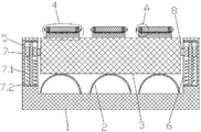
Fig. 1 is a schematic structural diagram of a damping building provided by the present invention;
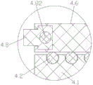
FIG. 2 is an enlarged view of portion A of FIG. 1;
fig. 3 is a schematic structural view of the shock-absorbing device.
Detailed Description
In order to make the objects, technical solutions and advantages of the present invention more clearly understood, the present invention is further described in detail below with reference to the accompanying drawings and embodiments. It should be understood that the specific embodiments described herein are merely illustrative of the invention and are not intended to limit the invention.
As shown in fig. 1, the utility model provides a pair of shock attenuation formula building house, including ground 1, the arched brace rod 2 of bottom equipartition in ground 1, brace rod 2 is the arch reinforcing bar of bending into, cement is laid earlier to the bottom in ground 1, all bury underground in cement with 2 both ends of arched brace rod, place building base plate 3 in the top of all brace rods 2, building base plate 3 is the reinforced cement board, support building base plate 3 through 2 of arched brace rod, the arch has good compressive property, can hold the building house, and brace rod 2 is arched, itself just has certain elasticity performance, can play preliminary shock attenuation to the building house.
A group of mounting grooves are arranged on each of four sides in the foundation 1, the number of the mounting grooves on each side is determined by the size of the house, in the embodiment, the number of the group of mounting grooves is 4, the rectangular box body 5 is vertically arranged in each mounting groove, the lifting box body 5 is fixed in the mounting groove by cement, a rectangular through groove 6 is arranged on the outer side surface of each rectangular box body 5, a sliding block 7 is connected in each rectangular box body 5 in a sliding way, one side of each sliding block 7 is welded with a connecting plate 8, each connecting plate 8 penetrates through the corresponding rectangular through groove 6, one side of each connecting plate 8 is fixedly connected with the building base plate 3 through cement, and a third spring 7.1 is welded below each sliding block 7, the lower end of each third spring 7.1 is welded on the lower end face in the rectangular box body 5, and the building base plate 3 is damped through the third springs 7.1.
All be equipped with the third guiding hole on every sliding block 7, all peg graft third guide bar 7.2 in every third guiding hole, every third guide bar 7.2 all with corresponding the coaxial setting of third spring 7.1, the tip of every third guide bar 7.2 all welds on a terminal surface in corresponding rectangle box body 5, leads sliding block 7 through third guide bar 7.2, makes sliding block 7 can be more smooth and easy slide from top to bottom in rectangle box body 5.
As shown in fig. 2 and 3, damping devices 4 are uniformly distributed above a building base plate 3, a building house is arranged above all the damping devices 4, each damping device 4 comprises a bottom plate 4.1, the bottom plates 4.1 are fixed on the building base plate 3 through cement, ball grooves are uniformly distributed on the upper side surfaces of the bottom plates 4.1, balls 4.2 are arranged in each ball groove, first sliding grooves 4.3 are arranged on the two side surfaces of the bottom plates 4.1, the two first sliding grooves 4.3 are oppositely arranged, first guide blocks 4.4 are slidably connected in each first sliding groove 4.3, first springs 4.5 are welded on the two end surfaces in each first sliding groove 4.3, corresponding first guide blocks 4.4 are welded between the two first springs 4.5, and fixing plates 4.41 are welded on one side surface of each first guide block 4.4.
All be equipped with first guiding hole on every first guide block 4.4, all peg graft first guide bar 4.42 in every first guiding hole, every first guide bar 4.42 all sets up in corresponding in first sliding tray 4.3, the both ends of first guide bar 4.42 weld respectively on two terminal surfaces in first sliding tray 4.3 promptly, lead first guide block 4.4 through first guide bar 4.42.
Still include dull and stereotyped 4.6, dull and stereotyped 4.6 sets up ball 4.2's top all is equipped with second sliding tray 4.7 on dull and stereotyped 4.6's both sides face, and two second sliding tray 4.7 set up relatively, and equal sliding connection second guide block 4.8 in every second sliding tray 4.7 all welds second spring 4.9 on the both ends face in every second sliding tray 4.7, and the welding is corresponding between two second spring 4.9 second guide block 4.8, every second guide block 4.8 all through L template 4.81 welding is corresponding fixed plate 4.41.
All be equipped with the second guiding hole on every second guide block 4.8, all peg graft second guide bar 4.82 in every second guiding hole, every second guide bar 4.82 all sets up correspondingly in the second sliding tray 4.7, the both ends of every second guide bar 4.82 weld respectively on the both ends face in the second sliding tray 4.7, can lead to second guide block 4.8 through second guide bar 4.82.
The flat plate 4.6 can move on the bottom plate 4.1 in a front-back and left-right direction, elastic shock absorption is realized through the first spring 4.5 and the second spring 4.9, shaking feeling is relieved, and friction between the flat plate 4.6 and the bottom plate 4.1 can be reduced through the balls 4.2.
Firstly, the building base plate 3 is supported by the arched support ribs 2, the arched support ribs 2 have good pressure resistance, and the arched support ribs 2 have certain elasticity, so that preliminary shock absorption can be performed on a building house; the building house can be vertically damped through the third springs 7.1, damping in all directions can be carried out on the building house through the two first springs 4.5 and the two second springs 4.9 on the damping device 4, when an earthquake occurs, the building house can be damped in all directions, so that the building house can be effectively protected, and the earthquake can be effectively relieved.
Claims (6)
1. A shock attenuation formula building house which characterized in that: comprises a foundation (1), arched support ribs (2) are uniformly distributed at the bottom in the foundation (1), a building base plate (3) is arranged above all the supporting ribs (2), a damping device (4) is uniformly distributed above the building base plate (3), a building house is arranged above all the damping devices (4), a group of mounting grooves are arranged on each of four sides in the foundation (1), a rectangular box body (5) is vertically arranged in each mounting groove, a rectangular through groove (6) is arranged on the outer side surface of each rectangular box body (5), sliding block (7) are connected in each rectangle box body (5) in a sliding mode, a connecting plate (8) is connected to one side of each sliding block (7), each connecting plate (8) penetrates through the corresponding rectangle through groove (6), and one side of each connecting plate (8) is connected with the building base plate (3).
2. The shock absorbing type architecture house as claimed in claim 1, wherein: the damping device (4) comprises a bottom plate (4.1), ball grooves are uniformly distributed in the side face above the bottom plate (4.1), balls (4.2) are arranged in each ball groove, first sliding grooves (4.3) are arranged on the two side faces of the bottom plate (4.1), the two first sliding grooves (4.3) are arranged oppositely, a first guide block (4.4) is connected in each first sliding groove (4.3) in a sliding manner, first springs (4.5) are connected on two end faces in each first sliding groove (4.3), a corresponding first guide block (4.4) is connected between the two first springs (4.5), and a fixing plate (4.41) is connected on one side face of each first guide block (4.4);
still include dull and stereotyped (4.6), dull and stereotyped (4.6) set up the top of ball (4.2), all be equipped with second sliding tray (4.7) on the both sides face of dull and stereotyped (4.6), two second sliding tray (4.7) set up relatively, equal sliding connection second guide block (4.8) in every second sliding tray (4.7), all connect second spring (4.9) on the both ends face in every second sliding tray (4.7), it is corresponding to connect between two second spring (4.9) second guide block (4.8), every second guide block (4.8) all connect corresponding through L template (4.81) fixed plate (4.41).
3. A shock absorbing type building house according to claim 2, wherein: each first guide block (4.4) is provided with a first guide hole, a first guide rod (4.42) is inserted into each first guide hole, and each first guide rod (4.42) is arranged in the corresponding first sliding groove (4.3).
4. A shock absorbing type building house according to claim 2, wherein: each second guide block (4.8) is provided with a second guide hole, each second guide hole is internally inserted with a second guide rod (4.82), and each second guide rod (4.82) is arranged in the corresponding second sliding groove (4.7).
5. The shock absorbing type architecture house as claimed in claim 1, wherein: every third spring (7.1) is all connected to the below of sliding block (7), and every third spring (7.1) all sets up correspondingly in rectangle box body (5), and the lower extreme of every third spring (7.1) all is connected correspondingly bottom in the rectangle box body (5).
6. The shock absorbing type architecture house of claim 5, wherein: every all be equipped with the third guiding hole on sliding block (7), all peg graft third guide bar (7.2) in every third guiding hole, every third guide bar (7.2) all with corresponding third spring (7.1) coaxial setting, the tip of every third guide bar (7.2) all is connected correspondingly on the terminal surface in the rectangle box body (5).
Priority Applications (1)
| Application Number | Priority Date | Filing Date | Title |
|---|---|---|---|
| CN201922077149.0U CN212153474U (en) | 2019-11-27 | 2019-11-27 | Shock attenuation formula building house |
Applications Claiming Priority (1)
| Application Number | Priority Date | Filing Date | Title |
|---|---|---|---|
| CN201922077149.0U CN212153474U (en) | 2019-11-27 | 2019-11-27 | Shock attenuation formula building house |
Publications (1)
| Publication Number | Publication Date |
|---|---|
| CN212153474U true CN212153474U (en) | 2020-12-15 |
Family
ID=73705309
Family Applications (1)
| Application Number | Title | Priority Date | Filing Date |
|---|---|---|---|
| CN201922077149.0U Expired - Fee Related CN212153474U (en) | 2019-11-27 | 2019-11-27 | Shock attenuation formula building house |
Country Status (1)
| Country | Link |
|---|---|
| CN (1) | CN212153474U (en) |
-
2019
- 2019-11-27 CN CN201922077149.0U patent/CN212153474U/en not_active Expired - Fee Related
Similar Documents
| Publication | Publication Date | Title |
|---|---|---|
| CN205153136U (en) | Vertical shock insulation support | |
| CN215977411U (en) | Building foundation construction shock isolation device | |
| CN208250900U (en) | A kind of steel construction shock mount | |
| CN210561685U (en) | Shock attenuation bridge structures | |
| CN212153474U (en) | Shock attenuation formula building house | |
| CN213418131U (en) | Building earthquake-resistant structure | |
| CN210529994U (en) | Multi-dimensional shock isolation and absorption device of interlayer shock isolation structure | |
| CN209907638U (en) | Engineering damping device used under foundation differential settlement and earthquake coupling | |
| CN216428599U (en) | Steel structure for novel anti-seismic and anti-shaking | |
| CN110939160A (en) | Shock attenuation formula building house | |
| CN214402965U (en) | Civil engineering antidetonation structure | |
| CN213773920U (en) | Building shock isolation device | |
| CN204876150U (en) | Compound shock isolation device that subtracts | |
| CN214117075U (en) | Damping device of civil engineering structure | |
| CN211597167U (en) | Damping device for building structure design | |
| CN211007125U (en) | Civil engineering antidetonation composite set | |
| CN205035904U (en) | Novel steel construction | |
| CN211547292U (en) | Bridge anti-seismic structure | |
| CN209816904U (en) | Underground structure antidetonation enclosure wall | |
| CN209958216U (en) | Bridge damping base | |
| CN111809763A (en) | A antidetonation support for building engineering | |
| CN211369116U (en) | Building anti-seismic device | |
| CN211523596U (en) | High-strength damping building house | |
| CN218437604U (en) | Underground structure anti-seismic enclosure wall | |
| CN214329384U (en) | Damping and anti-seismic structure of prefabricated building |
Legal Events
| Date | Code | Title | Description |
|---|---|---|---|
| GR01 | Patent grant | ||
| GR01 | Patent grant | ||
| CF01 | Termination of patent right due to non-payment of annual fee |
Granted publication date: 20201215 Termination date: 20211127 |
|
| CF01 | Termination of patent right due to non-payment of annual fee |