CN212151885U - High-efficient multistage sewage treatment plant - Google Patents
High-efficient multistage sewage treatment plant Download PDFInfo
- Publication number
- CN212151885U CN212151885U CN202020470436.8U CN202020470436U CN212151885U CN 212151885 U CN212151885 U CN 212151885U CN 202020470436 U CN202020470436 U CN 202020470436U CN 212151885 U CN212151885 U CN 212151885U
- Authority
- CN
- China
- Prior art keywords
- aeration
- separation device
- impurity separation
- sewage treatment
- water
- Prior art date
- Legal status (The legal status is an assumption and is not a legal conclusion. Google has not performed a legal analysis and makes no representation as to the accuracy of the status listed.)
- Expired - Fee Related
Links
Images


Abstract
The utility model relates to a sewage treatment technical field just discloses a high-efficient multistage sewage treatment plant, including the base, the top of base is provided with impurity separation device, and the top of base and the right side that is located impurity separation device are provided with aeration equipment, and aeration equipment fixed welding is in the up end of base, and the top of base and the right side that is located aeration equipment are provided with filter equipment. This high-efficient multistage sewage treatment plant, through having set up impurity separation device, impurity separation device's internally mounted has the partition sieve, separate the screening to the solid impurity in the sewage, avoid influencing the sewage treatment effect, improve purification efficiency, the below fixed mounting who separates the sieve has U type to deposit the board, the U type is regional to deposiing the mud in the sewage, avoid causing the pipeline to block, strike off accumulational impurity on separating the sieve through setting up electric telescopic handle and scraper blade, avoid impurity to pile up, improve purification efficiency.
Description
Technical Field
The utility model relates to a high-efficient multistage sewage treatment plant technical field specifically is a high-efficient multistage sewage treatment plant.
Background
The improvement of people's living conditions, the destruction to the environment is serious day by day, especially the emission of sewage influences people's living environment, along with the improvement of people's environmental protection consciousness, the construction sewage treatment station is used for handling resident domestic sewage, but the treatment cost is higher like this, and the troublesome efficiency ratio of processing is lower, and the treatment mode is single moreover, and sewage treatment is not thorough, consequently needs a novel high-efficient sewage treatment plant to improve sewage treatment efficiency.
SUMMERY OF THE UTILITY MODEL
Technical problem to be solved
The utility model provides a to prior art not enough, the utility model provides a high-efficient multistage sewage treatment plant has solved the lower and single incomplete problem of processing of treatment mode of sewage treatment efficiency.
(II) technical scheme
For realizing the above-mentioned sewage treatment efficiency that improves, improve sewage purification rate, reduce sewage discharge polluted environment's purpose, the utility model provides a following technical scheme: the utility model provides a high-efficient multistage sewage treatment plant, includes the base, the top of base is provided with impurity separation device, impurity separation device fixed weld in the up end of base, the top of base just is located impurity separation device's right side is provided with aeration equipment, aeration equipment fixed weld in the up end of base, the top of base just is located aeration equipment's right side is provided with filter equipment, filter equipment fixed weld in the up end of base.
Preferably, the impurity separating device comprises a water inlet, a separating sieve plate, a U-shaped settling plate, a water outlet, an electric telescopic rod and a scraper, the water inlet is arranged above the impurity separating device, the water inlet is fixedly welded at the upper outer end of the impurity separating device, the separating sieve plate is arranged inside the impurity separating device, the separating sieve plate is fixedly connected with the inner wall of the impurity separating device through bolts, the U-shaped settling plate is arranged below the separating sieve plate, the U-shaped settling plate is fixedly arranged inside the impurity separating device through bolts, the impurity separating device is close to one side of the aeration device and provided with the water outlet below the U-shaped settling plate, the water outlet is fixedly welded at the side wall of the impurity separating device, the electric telescopic rod is fixedly arranged at the outer side wall of the impurity separating device through bolts, electric telescopic handle's flexible end runs through impurity separator's lateral wall and extend to inside, electric telescopic handle's one end has the scraper blade through bolt fixed mounting, the scraper blade with the up end butt of separating the sieve.
Preferably, the aeration device comprises a first water pump, a rotating motor, a transmission shaft, a stirring rod, a support rod and a drainage through hole, the first water pump is arranged above the aeration device and fixedly installed at the upper outer end of the aeration device through bolts, a water inlet of the first water pump is communicated with a water outlet through a water pipe, the water outlet of the first water pump is communicated with the inner part of the aeration device through a water pipe, the rotating motor is arranged above the aeration device and fixedly installed at the top outer end of the aeration device through bolts, one end of an output shaft of the rotating motor is fixedly welded with one end of the transmission shaft, the other end of the transmission shaft penetrates through the upper wall of the aeration device and extends to the inner part, the stirring rod is arranged on the outer surface of the transmission shaft at even intervals and is fixedly connected with the transmission shaft through bolts, the two ends of the stirring rod are fixedly welded with the supporting rods, a drainage through hole is formed in the lower portion of one side, close to the filtering device, of the aeration device, and the drainage through hole is fixedly welded to the side wall of the aeration device.
Preferably, affiliated aeration equipment still includes oxygen tank, breather pipe and aeration dish, the oxygen tank set up in aeration equipment's outside, the one end of breather pipe with the oxygen tank intercommunication, the other end of breather pipe runs through aeration equipment's lateral wall and extend to inside, the other end fixedly connected with aeration dish of breather pipe, aeration dish with the breather pipe intercommunication, the air vent has been seted up on the aeration dish.
Preferably, the filtering device comprises a second water pump, a quartz sand filling layer, an activated carbon filling layer and a discharge port, the second water suction pump is fixedly arranged above the filtering device through bolts, a water inlet of the second water suction pump is communicated with the water drainage through hole through a water pipe, the water outlet of the second water pump is communicated with the inside of the filtering device through a water pipe, one end of the inside of the filtering device, which is close to the second water pump, is provided with a quartz sand filling layer, the quartz sand filling layer is fixedly arranged in the filtering device through bolts, the activated carbon filling layer is arranged below the quartz sand filling layer, the activated carbon filling layer is fixedly installed in the filtering device through bolts, and the filtering device is far away from one side of the aeration device and is positioned below the activated carbon filling layer and provided with the discharge port.
Preferably, the specific model of the rotating motor is Y180L-8.
Preferably, water leakage holes are formed in two ends of the U-shaped settling plate, and the diameter of the through hole for separating the sieve plate is larger than that of the U-shaped settling plate.
Compared with the prior art, the utility model provides a high-efficient multistage sewage treatment plant possesses following beneficial effect:
1. this high-efficient multistage sewage treatment plant, through having set up impurity separation device, impurity separation device's internally mounted has the partition sieve, separate the screening to the solid impurity in the sewage, avoid influencing the sewage treatment effect, improve purification efficiency, the below fixed mounting who separates the sieve has U type to deposit the board, the U type is regional to deposiing the mud in the sewage, avoid causing the pipeline to block, strike off accumulational impurity on separating the sieve through setting up electric telescopic handle and scraper blade, avoid impurity to pile up, improve purification efficiency.
2. This high-efficient multistage sewage treatment plant, through setting up aeration equipment, rotating electrical machines and transmission shaft fixed connection, the fixed surface of transmission shaft is provided with the puddler, the both ends fixed mounting of puddler has branch, rotating electrical machines drives the puddler through the transmission shaft and rotates the sewage in the aeration equipment and stir, improve aeration efficiency, accelerate sewage purification, through setting up oxygen case and aeration dish, aeration dish passes through breather pipe and oxygen case intercommunication, improve the sewage oxygen concentration in the aeration equipment through setting up the aeration dish, accelerate the decomposition of organic matter in the sewage, through setting up filter equipment, be provided with quartzy sand filling layer and active carbon filling layer among the filter equipment, through quartzy sand filling layer and active carbon filling layer, filter tiny impurity in the sewage, improve the sewage purification rate.
Drawings
FIG. 1 is a schematic structural view of the present invention;
FIG. 2 is a rear view of the present invention;
FIG. 3 is a schematic structural view of the impurity separating device of the present invention;
FIG. 4 is a schematic structural view of the aeration apparatus of the present invention;
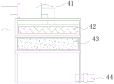
fig. 5 is a schematic structural view of the filtering device of the present invention.
Wherein: 1. a base; 2. an impurity separation device; 3. an aeration device; 4. a filtration device; 21. a water inlet; 22. separating the sieve plate; 23. a U-shaped settling plate; 24. a water outlet; 25. an electric telescopic rod; 26. a squeegee; 31. a first water pump; 32. a rotating electric machine; 33. a drive shaft; 34. a stirring rod; 35. a strut; 36. a drain through hole; 37. an oxygen tank; 38. a breather pipe; 39. an aeration disc; 41. a second water pump; 42. a quartz sand filling layer; 43. an activated carbon filling layer; 44. and (7) discharging the air.
Detailed Description
The technical solutions in the embodiments of the present invention will be described clearly and completely with reference to the accompanying drawings in the embodiments of the present invention, and it is obvious that the described embodiments are only some embodiments of the present invention, not all embodiments. Based on the embodiments in the present invention, all other embodiments obtained by a person skilled in the art without creative work belong to the protection scope of the present invention.
Please refer to fig. 1-5, the utility model provides a high-efficient multistage sewage treatment plant, including base 1, base 1's top is provided with impurity separation device 2, impurity separation device 2 fixed welding is in base 1's up end, base 1's top and the right side that is located impurity separation device 2 are provided with aeration equipment 3, aeration equipment 3 fixed welding is in base 1's up end, base 1's top and the right side that is located aeration equipment 3 are provided with filter equipment 4, filter equipment 4 fixed welding is in base 1's up end.
The impurity separation device 2 comprises a water inlet 21, a separation sieve plate 22, a U-shaped precipitation plate 23, a water outlet 24, an electric telescopic rod 25 and a scraper 26, the water inlet 21 is arranged above the impurity separation device 2, the water inlet 21 is fixedly welded at the upper end of the outer part of the impurity separation device 2, the separation sieve plate 22 is arranged inside the impurity separation device 2, the separation sieve plate 22 is fixedly connected with the inner wall of the impurity separation device 2 through bolts, the U-shaped precipitation plate 23 is arranged below the separation sieve plate 22, the U-shaped precipitation plate 23 is fixedly arranged inside the impurity separation device 2 through bolts, water leakage holes are formed at two ends of the U-shaped precipitation plate 23, the diameter of a through hole of the separation sieve plate 22 is larger than that of the U-shaped precipitation plate 23, the water outlet 24 is formed below the U-shaped precipitation plate 23 and close to one side of the aeration device 3, and the water outlet, electric telescopic handle 25 passes through bolt fixed mounting in impurity separation device 2's outside lateral wall, electric telescopic handle 25's flexible end runs through impurity separation device 2's lateral wall and extends to inside, bolt fixed mounting has scraper blade 26 is passed through to electric telescopic handle 25's one end, scraper blade 26 and the up end butt of separating sieve 22, through having set up impurity separation device 2, impurity separation device 2's internally mounted has separation sieve 22, separate the screening to the solid impurity in the sewage, avoid influencing the sewage treatment effect, improve purification efficiency, the below fixed mounting who separates sieve 22 has U type precipitate plate 23, the mud in the U type region to the sewage deposits, avoid causing the pipeline to block, strike off through setting up electric telescopic handle 25 and scraper blade 26 accumulational impurity on separating sieve 22, avoid impurity to pile up, improve purification efficiency.
The aeration device 3 comprises a first water pump 31, a rotating motor 32, a transmission shaft 33, a stirring rod 34, a support rod 35 and a water drainage through hole 36, the first water pump 31 is arranged above the aeration device 3, the first water pump 31 is fixedly arranged at the upper end of the outside of the aeration device 3 through a bolt, a water inlet of the first water pump 31 is communicated with a water outlet 24 through a water pipe, a water outlet of the first water pump 31 is communicated with the inside of the aeration device 3 through a water pipe, the rotating motor 32 is arranged above the aeration device 3, the specific model of the rotating motor 32 is Y180L-8, the rotating motor 32 is fixedly arranged at the top end of the outside of the aeration device 3 through a bolt, one end of an output shaft of the rotating motor 32 is fixedly welded with one end of the transmission shaft 33, the other end of the transmission shaft 33 penetrates through the upper wall of the aeration device 3 and extends to the inside, the stirring rod 34 is fixedly connected with the transmission shaft 33 through a bolt, two ends of the stirring rod 34 are fixedly welded with supporting rods 35, a drainage through hole 36 is formed below one side of the aeration device 3 close to the filtering device 4, the drainage through hole 36 is fixedly welded on the side wall of the aeration device 3, the aeration device 3 further comprises an oxygen tank 37, a vent pipe 38 and an aeration disc 39, the oxygen tank 37 is arranged outside the aeration device 3, one end of the vent pipe 38 is communicated with the oxygen tank 37, the other end of the vent pipe 38 penetrates through the side wall of the aeration device 3 and extends to the inside, the other end of the vent pipe 38 is fixedly connected with the aeration disc 39, the aeration disc 39 is communicated with the vent pipe 38, an air vent is formed in the aeration disc 39, through the arrangement of the aeration device 3, the rotating motor 32 is fixedly connected with the transmission shaft 33, the stirring rod 34 is fixedly arranged on the, the rotating electrical machines 32 drives the stirring rod 34 through the transmission shaft 33 to rotate and stir the sewage in the aeration device 3, so that the aeration efficiency is improved, the sewage purification is accelerated, the aeration disc 39 is communicated with the oxygen tank 37 through the aeration pipe 38 by arranging the oxygen tank 37 and the aeration disc 39, the oxygen concentration of the sewage in the aeration device 3 is improved by arranging the aeration disc 39, and the decomposition of organic matters in the sewage is accelerated.
The filtering device 4 comprises a second water pump 41, a quartz sand filling layer 42, an activated carbon filling layer 43 and a discharge port 44, the second water pump 41 is fixedly arranged above the filtering device 4 through bolts, a water inlet of the second water pump 41 is communicated with the water discharge through hole 36 through a water pipe, a water outlet of the second water pump 41 is communicated with the inside of the filtering device 4 through a water pipe, the quartz sand filling layer 42 is arranged at one end of the inside of the filtering device 4 close to the second water pump 41, the quartz sand filling layer 42 is fixedly arranged inside the filtering device 4 through bolts, the activated carbon filling layer 43 is arranged below the quartz sand filling layer 42, the activated carbon filling layer 43 is fixedly arranged inside the filtering device 4 through bolts, the discharge port 44 is arranged at one side of the filtering device 4 far away from the aeration device 3 and below the activated carbon filling layer 43, the filtering device 4 is provided with the quartz sand filling layer 42 and the activated carbon filling layer 43, through quartz sand filling layer 42 and active carbon filling layer 43, filter the tiny impurity in the sewage, improve sewage purification rate.
When the device is used, sewage to be treated is introduced into the impurity separation device 2 through the water inlet 21, solid impurities in the sewage are screened and separated through the separation sieve plate 22, when the impurities on the separation sieve plate 22 are accumulated more, the electric telescopic rod 25 is started to drive the scraper 26 to scrape the impurities above the separation sieve plate 22, the sewage continuously flows downwards, the smaller impurities in the sewage are precipitated in the U-shaped groove of the U-shaped precipitation plate 23 through the U-shaped precipitation plate 23, the sewage continuously flows downwards, the sewage treated in the impurity separation device 2 is pumped into the aeration device 3 through the first water suction pump 31, the rotating motor 32 is started to drive the stirring rod 34 and the support rod 35 to rotate through the transmission shaft 33, the sewage is fully stirred, oxygen in the oxygen tank 37 is sprayed out through the aeration disc 39 through the vent pipe 38, the oxygen content of the sewage in the aeration device 3 is improved, and the decomposition of organic matters is accelerated, the sewage treated in the aeration device 3 is sent into the filtering device 4 through the second water suction pump 41, the sewage is filtered through the quartz sand filling layer 42 and the activated carbon filling layer 43, residual impurities in the sewage are effectively removed, the sewage purification efficiency is improved, and the filtered sewage is discharged through the discharge port 44.
Although embodiments of the present invention have been shown and described, it will be appreciated by those skilled in the art that changes, modifications, substitutions and alterations can be made in these embodiments without departing from the principles and spirit of the invention, the scope of which is defined in the appended claims and their equivalents.
Claims (7)
1. The utility model provides a high-efficient multistage sewage treatment plant, includes base (1), its characterized in that: the top of base (1) is provided with impurity separation device (2), impurity separation device (2) fixed weld in the up end of base (1), the top of base (1) just is located the right side of impurity separation device (2) is provided with aeration equipment (3), aeration equipment (3) fixed weld in the up end of base (1), the top of base (1) just is located the right side of aeration equipment (3) is provided with filter equipment (4), filter equipment (4) fixed weld in the up end of base (1).
2. The high efficiency multistage sewage treatment plant according to claim 1, characterized in that: the impurity separation device (2) comprises a water inlet (21), a separation sieve plate (22), a U-shaped precipitation plate (23), a water outlet (24), an electric telescopic rod (25) and a scraper (26), the water inlet (21) is arranged above the impurity separation device (2), the water inlet (21) is fixedly welded at the upper end of the outer part of the impurity separation device (2), the separation sieve plate (22) is arranged inside the impurity separation device (2), the separation sieve plate (22) is fixedly connected with the inner wall of the impurity separation device (2) through bolts, the U-shaped precipitation plate (23) is arranged below the separation sieve plate (22), the U-shaped precipitation plate (23) is fixedly arranged inside the impurity separation device (2) through bolts, the impurity separation device (2) is close to one side of the aeration device (3) and is positioned below the U-shaped precipitation plate (23) and is provided with the water outlet (24), delivery port (24) fixed weld in the lateral wall of impurity separation device (2), electric telescopic handle (25) through bolt fixed mounting in the outside lateral wall of impurity separation device (2), electric telescopic handle (25) flexible end runs through the lateral wall of impurity separation device (2) and extends to inside, electric telescopic handle (25) one end has scraper blade (26) through bolt fixed mounting, scraper blade (26) with the up end butt of separating sieve (22).
3. The high efficiency multistage sewage treatment plant according to claim 2, characterized in that: the aeration device (3) comprises a first water suction pump (31), a rotating motor (32), a transmission shaft (33), a stirring rod (34), a support rod (35) and a water drainage through hole (36), wherein the first water suction pump (31) is arranged above the aeration device (3), the first water suction pump (31) is fixedly arranged at the upper outer end of the aeration device (3) through bolts, a water inlet of the first water suction pump (31) is communicated with a water outlet (24) through a water pipe, a water outlet of the first water suction pump (31) is communicated with the inner part of the aeration device (3) through a water pipe, the rotating motor (32) is arranged above the aeration device (3), the rotating motor (32) is fixedly arranged at the top outer end of the aeration device (3) through bolts, one end of an output shaft of the rotating motor (32) is fixedly welded with one end of the transmission shaft (33), the other end of transmission shaft (33) runs through the upper wall of aeration equipment (3) and extends to inside, transmission shaft (33) surface interval is even is provided with puddler (34), puddler (34) pass through the bolt with transmission shaft (33) fixed connection, the fixed welding in both ends of puddler (34) has branch (35), aeration equipment (3) are close to one side below of filter equipment (4) has seted up drainage through hole (36), drainage through hole (36) fixed welding in the lateral wall of aeration equipment (3).
4. The high efficiency multistage sewage treatment plant according to claim 3, characterized in that: the aeration device (3) further comprises an oxygen tank (37), a vent pipe (38) and an aeration disc (39), wherein the oxygen tank (37) is arranged outside the aeration device (3), one end of the vent pipe (38) is communicated with the oxygen tank (37), the other end of the vent pipe (38) penetrates through the side wall of the aeration device (3) and extends to the inside, the other end of the vent pipe (38) is fixedly connected with the aeration disc (39), the aeration disc (39) is communicated with the vent pipe (38), and the aeration disc (39) is provided with a vent hole.
5. The high efficiency multistage sewage treatment plant according to claim 3, characterized in that: filter equipment (4) include second suction pump (41), quartz sand filling layer (42), activated carbon filling layer (43) and discharge port (44), second suction pump (41) through bolt fixed mounting in the top of filter equipment (4), the water inlet of second suction pump (41) lead to pipe with drainage through hole (36) intercommunication, the delivery port lead to pipe of second suction pump (41) with the inside intercommunication of filter equipment (4), inside being close to of filter equipment (4) the one end of second suction pump (41) is provided with quartz sand filling layer (42), quartz sand filling layer (42) through bolt fixed mounting in the inside of filter equipment (4), the below of quartz sand filling layer (42) is provided with activated carbon filling layer (43), activated carbon filling layer (43) through bolt fixed mounting in the inside of filter equipment (4), the filtering device (4) is far away from one side of the aeration device (3) and is provided with the discharge port (44) below the activated carbon filling layer (43).
6. The high efficiency multistage sewage treatment plant according to claim 3, characterized in that: the specific model of the rotating motor (32) is Y180L-8.
7. The high efficiency multistage sewage treatment plant according to claim 2, characterized in that: the two ends of the U-shaped settling plate (23) are provided with water leakage holes, and the diameter of the through hole of the separating sieve plate (22) is larger than that of the U-shaped settling plate (23).
Priority Applications (1)
| Application Number | Priority Date | Filing Date | Title |
|---|---|---|---|
| CN202020470436.8U CN212151885U (en) | 2020-04-02 | 2020-04-02 | High-efficient multistage sewage treatment plant |
Applications Claiming Priority (1)
| Application Number | Priority Date | Filing Date | Title |
|---|---|---|---|
| CN202020470436.8U CN212151885U (en) | 2020-04-02 | 2020-04-02 | High-efficient multistage sewage treatment plant |
Publications (1)
| Publication Number | Publication Date |
|---|---|
| CN212151885U true CN212151885U (en) | 2020-12-15 |
Family
ID=73726441
Family Applications (1)
| Application Number | Title | Priority Date | Filing Date |
|---|---|---|---|
| CN202020470436.8U Expired - Fee Related CN212151885U (en) | 2020-04-02 | 2020-04-02 | High-efficient multistage sewage treatment plant |
Country Status (1)
| Country | Link |
|---|---|
| CN (1) | CN212151885U (en) |
Cited By (1)
| Publication number | Priority date | Publication date | Assignee | Title |
|---|---|---|---|---|
| CN112850940A (en) * | 2021-04-16 | 2021-05-28 | 丽水市太行环境科技有限公司 | Domestic wastewater recycling device and treatment method thereof |
-
2020
- 2020-04-02 CN CN202020470436.8U patent/CN212151885U/en not_active Expired - Fee Related
Cited By (1)
| Publication number | Priority date | Publication date | Assignee | Title |
|---|---|---|---|---|
| CN112850940A (en) * | 2021-04-16 | 2021-05-28 | 丽水市太行环境科技有限公司 | Domestic wastewater recycling device and treatment method thereof |
Similar Documents
| Publication | Publication Date | Title |
|---|---|---|
| CN212151885U (en) | High-efficient multistage sewage treatment plant | |
| CN215886443U (en) | High-efficient air supporting water treatment facilities | |
| CN214087874U (en) | Biological rotating disc with filtering structure | |
| CN112299601A (en) | Organic wastewater and sewage treatment equipment and sewage treatment method | |
| CN213865741U (en) | Dephosphorization formula sewage treatment integration equipment | |
| CN215712218U (en) | High-efficient recovery unit of PCB board waste water | |
| CN213295093U (en) | High-efficiency sewage purification biochemical pool | |
| CN211497296U (en) | Sewage treatment plant based on MBR | |
| CN210287069U (en) | Farmland sewage treatment plant | |
| CN217051858U (en) | Integrative domestic sewage treatment | |
| CN111533345A (en) | PCB board china ink effluent disposal system | |
| CN218879675U (en) | Waste water decoloration processing apparatus | |
| CN220376456U (en) | Sewage treatment device | |
| CN220098724U (en) | Precipitator for coal washing wastewater treatment | |
| CN213112886U (en) | Integrated sewage treatment device | |
| CN215517008U (en) | Electro-catalytic oxidation equipment for wastewater treatment | |
| CN217947793U (en) | Wastewater aeration device for water supply and drainage | |
| CN214004278U (en) | Flocculation filtration purification's integration printing sewage treatment plant | |
| CN216737970U (en) | Domestic sewage purification device | |
| CN217808981U (en) | Distributed domestic sewage treatment equipment | |
| CN220116390U (en) | Mining wastewater treatment assembly | |
| CN211659414U (en) | Filter cloth filter | |
| CN213112956U (en) | Rural domestic sewage treatment system | |
| CN212687808U (en) | Sewage treatment device | |
| CN217103334U (en) | Waste water purification equipment for ore dressing |
Legal Events
| Date | Code | Title | Description |
|---|---|---|---|
| GR01 | Patent grant | ||
| GR01 | Patent grant | ||
| CF01 | Termination of patent right due to non-payment of annual fee | ||
| CF01 | Termination of patent right due to non-payment of annual fee |
Granted publication date: 20201215 |