CN212146680U - Die cutting equipment for processing conductive adhesive - Google Patents
Die cutting equipment for processing conductive adhesive Download PDFInfo
- Publication number
- CN212146680U CN212146680U CN202020728858.0U CN202020728858U CN212146680U CN 212146680 U CN212146680 U CN 212146680U CN 202020728858 U CN202020728858 U CN 202020728858U CN 212146680 U CN212146680 U CN 212146680U
- Authority
- CN
- China
- Prior art keywords
- close
- processing
- cutting equipment
- pressing
- fixed mounting
- Prior art date
- Legal status (The legal status is an assumption and is not a legal conclusion. Google has not performed a legal analysis and makes no representation as to the accuracy of the status listed.)
- Active
Links
Images

Abstract
The utility model discloses a die cutting equipment for processing based on conducting resin, including the processing platform, the lower surface of processing platform is close to the equal fixed mounting in both sides position and has the supporting legs, and the upper surface of processing platform is close to intermediate position fixed mounting and has places the platform, the upper surface of processing platform is close to marginal position fixed mounting and has the guided way, the last surface movable mounting of guided way has the slide, the top of slide supports there is the support frame, the top of support frame is close to intermediate position fixed mounting and has the cylinder, the output of cylinder even has the transfer line, the end position of transfer line is connected with the cross cutting tool bit, the last fixed surface of cross cutting tool bit installs the adapter, the adapter cover is established at the end position of transfer line. A based on cross cutting equipment is used in conducting resin processing, can compress tightly the direction glue that needs processed, and can conveniently take out the cross cutting and add the sweeps that produces.
Description
Technical Field
The utility model relates to a conducting resin processing equipment field, in particular to based on cross cutting equipment is used in conducting resin processing.
Background
The conductive adhesive is an adhesive which has certain conductivity after being cured or dried. It can connect multiple conductive materials together to form an electrical path between the connected materials. In the electronic industry, conductive adhesive becomes an indispensable new material, and the die cutting equipment for processing the conductive adhesive is common equipment for die cutting the conductive adhesive; the existing die cutting equipment for processing conductive adhesive cannot compress guide adhesive to be processed when in use, and cannot ensure the cleanness of the surface of the die cutting equipment.
SUMMERY OF THE UTILITY MODEL
The utility model discloses a main aim at provides a based on cross cutting equipment is used in conducting resin processing can effectively solve and can not compress tightly and can not guarantee the clear problem on cross cutting equipment surface to the direction glue that needs processing in the background art.
In order to achieve the above purpose, the utility model adopts the following technical scheme:
a die cutting device for processing conductive adhesive comprises a processing table, supporting legs are fixedly arranged on the lower surface of the processing table close to the two sides, a placing table is fixedly arranged on the upper surface of the processing table close to the middle position, a guide rail is fixedly arranged on the upper surface of the processing table close to the edge position, a sliding seat is movably arranged on the upper surface of the guide rail, a supporting frame is supported at the top of the sliding seat, the top of the supporting frame is fixedly provided with an air cylinder near the middle position, the output end of the air cylinder is connected with a transmission rod, the end of the transmission rod is connected with a die cutting tool bit, the upper surface of the die cutting tool bit is fixedly provided with an adapter head, the joint sleeve is arranged at the end position of the transmission rod, the outer side position of the upper surface of the processing table close to the placing table is connected with a pressing mechanism, and the inner side of the supporting leg is connected with an air draft device.
Preferably, hold-down mechanism comprises L type seat, compression bar, compact heap and pressure spring, L type seat fixed mounting is at the upper surface of processing platform, the compression bar runs through in the top of L type seat, the compact heap is fixed in the bottom of compression bar, pressure spring's one end is fixed in the surface of compact heap, and pressure spring's the other end is fixed in the surface of L type seat, pressure spring sets up the surface at the compression bar, and hold-down mechanism can compress tightly the direction glue that needs processing to can improve the relative stability when the direction is glued and is processed.
Preferably, the pressing block is movably connected with the L-shaped seat through a pressing rod and a pressing spring.
Preferably, updraft ventilator comprises air exhauster, brace table, collection box, a connecting pipe and No. two connecting pipes, brace table fixed mounting is close to the intermediate position in the inboard of supporting legs, collection box fixed mounting is close to the position of bottom in the inboard of supporting legs, the air exhauster is fixed in the upper surface of brace table, a connecting pipe sets up between air exhauster and processing platform, No. two connecting pipes set up between air exhauster and collection box, and updraft ventilator can conveniently take out the cross cutting and add the sweeps that produce to can guarantee the cleanness on cross cutting equipment surface.
Preferably, the exhaust fan is fixedly connected with the supporting legs through the supporting table.
Preferably, a blanking port is formed in the processing table, and the blanking port facilitates blanking of waste materials.
Compared with the prior art, the utility model discloses following beneficial effect has: this based on cross cutting equipment is used in conducting resin processing through the hold-down mechanism who sets up, can compress tightly the direction glue that needs processed to can improve the relative stability when the direction is glued and is processed, through the updraft ventilator who sets up, can conveniently take out the cross cutting and add the sweeps that produces, thereby can guarantee the cleanness on cross cutting equipment surface.
Drawings
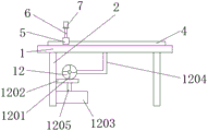
Fig. 1 is a schematic view of the overall structure of the die cutting equipment for processing conductive adhesive of the present invention;
fig. 2 is a side view of the overall structure of the die cutting equipment for processing conductive adhesive according to the present invention;
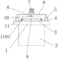
fig. 3 is the utility model relates to a hold-down mechanism's schematic structure based on cross cutting equipment for conducting resin processing.
In the figure: 1. a processing table; 2. supporting legs; 3. a placing table; 4. a guide rail; 5. a slide base; 6. a support frame; 7. a cylinder; 8. a transmission rod; 9. a die cutting tool bit; 10. an adaptor head; 11. a hold-down mechanism; 1101. an L-shaped seat; 1102. a hold down bar; 1103. a compression block; 1104. a compression spring; 12. an air draft device; 1201. an exhaust fan; 1202. a support table; 1203. a recycling bin; 1204. a first connecting pipe; 1205. and a second connecting pipe.
Detailed Description
In order to make the technical means, creation features, achievement purposes and functions of the present invention easy to understand, the present invention is further described below with reference to the following embodiments.
In the description of the present invention, it should be noted that the terms "upper", "lower", "inner", "outer", "front end", "rear end", "both ends", "one end", "the other end" and the like indicate orientations or positional relationships based on the orientations or positional relationships shown in the drawings, and are only for convenience of description and simplification of description, but do not indicate or imply that the device or element to which the reference is made must have a specific orientation, be constructed in a specific orientation, and be operated, and thus, should not be construed as limiting the present invention. Furthermore, the terms "first" and "second" are used for descriptive purposes only and are not to be construed as indicating or implying relative importance.
In the description of the present invention, it is to be noted that, unless otherwise explicitly specified or limited, the terms "mounted," "disposed," "connected," and the like are to be construed broadly, and for example, "connected" may be either fixedly connected or detachably connected, or integrally connected; can be mechanically or electrically connected; they may be connected directly or indirectly through intervening media, or they may be interconnected between two elements. The specific meaning of the above terms in the present invention can be understood in specific cases to those skilled in the art.
As shown in figures 1-3, the die cutting equipment for processing based on the conductive adhesive comprises a processing table 1, supporting legs 2 are fixedly arranged on the lower surface of the processing table 1 near to the two sides, a placing table 3 is fixedly arranged on the upper surface of the processing table 1 close to the middle position, a guide rail 4 is fixedly arranged on the upper surface of the processing table 1 close to the edge position, a sliding seat 5 is movably arranged on the upper surface of the guide rail 4, a supporting frame 6 is supported on the top of the sliding seat 5, an air cylinder 7 is fixedly arranged on the top of the supporting frame 6 close to the middle position, an output end of the air cylinder 7 is connected with a transmission rod 8, an end head position of the transmission rod 8 is connected with a die cutting tool bit 9, an adapter 10 is fixedly arranged on the upper surface of the die cutting tool bit 9, the adapter 10 is sleeved on the end head position of the transmission rod 8, a pressing mechanism 11 is connected on the upper surface of the processing table 1;
the pressing mechanism 11 comprises an L-shaped seat 1101, a pressing rod 1102, a pressing block 1103 and a pressing spring 1104, wherein the L-shaped seat 1101 is fixedly installed on the upper surface of the processing table 1, the pressing rod 1102 penetrates through the top of the L-shaped seat 1101, the pressing block 1103 is fixed at the bottom end of the pressing rod 1102, one end of the pressing spring 1104 is fixed on the outer surface of the pressing block 1103, the other end of the pressing spring 1104 is fixed on the outer surface of the L-shaped seat 1101, and the pressing spring 1104 is sleeved on the outer surface of the pressing rod 1102; the hold-down block 1103 is movably connected with the L-shaped seat 1101 through a hold-down rod 1102 and a hold-down spring 1104; the air draft device 12 comprises an exhaust fan 1201, a support platform 1202, a recovery box 1203, a first connecting pipe 1204 and a second connecting pipe 1205, the support platform 1202 is fixedly installed on the inner side of the support leg 2 close to the middle position, the recovery box 1203 is fixedly installed on the inner side of the support leg 2 close to the bottom position, the exhaust fan 1201 is fixed on the upper surface of the support platform 1202, the first connecting pipe 1204 is arranged between the exhaust fan 1201 and the processing platform 1, and the second connecting pipe 1205 is arranged between the exhaust fan 1201 and the recovery box 1203; the exhaust fan 1201 is fixedly connected with the supporting leg 2 through a supporting platform 1202; the processing table 1 is internally provided with a blanking port.
It should be noted that, the utility model relates to a die cutting equipment for processing based on conductive adhesive, when in use, the processing platform 1 forms the main body of the whole die cutting equipment for processing based on conductive adhesive, the guiding adhesive is placed on the placing platform 3, the compressing block 1103 moves relatively with the L-shaped seat 1101 through the compressing rod 1102 and the compressing spring 1104, the guiding adhesive to be processed can be compressed, thereby the relative stability when the guiding adhesive is processed can be improved, the cylinder 7 is started, the cylinder 7 drives the die cutting tool bit 9 to move vertically through the transmission rod 8 to perform die cutting on the guiding adhesive, the supporting frame 6 can change the position through the sliding seat 5 sliding on the surface of the guiding rail 4, the die cutting of the conductive adhesive at different positions on the placing platform 3 is realized, the exhaust fan 1201 is started, the scrap on the surface of the processing platform 1 is pumped into the recycling box 1203 through the first connecting pipe 1204 and the second connecting pipe 1205, the cleanness of the surface of the die cutting equipment can be ensured.
The basic principles and the main features of the invention and the advantages of the invention have been shown and described above. It will be understood by those skilled in the art that the present invention is not limited to the above embodiments, and that the foregoing embodiments and descriptions are provided only to illustrate the principles of the present invention without departing from the spirit and scope of the present invention. The scope of the invention is defined by the appended claims and equivalents thereof.
Claims (6)
1. The utility model provides a processing is with cross cutting equipment based on conducting resin which characterized in that: including processing platform (1), the lower surface of processing platform (1) is close to the equal fixed mounting in both sides position and has supporting legs (2), and the upper surface of processing platform (1) is close to intermediate position fixed mounting and place platform (3), the upper surface of processing platform (1) is close to marginal position fixed mounting and has guided way (4), the last movable surface mounting of guided way (4) has slide (5), the top of slide (5) supports there is support frame (6), the top of support frame (6) is close to intermediate position fixed mounting and has cylinder (7), the output of cylinder (7) even has transfer line (8), the end position of transfer line (8) is connected with cross cutting tool bit (9), the last fixed surface of cross cutting tool bit (9) installs adapter (10), adapter (10) cover is established in the end position of transfer line (8), the outer side position that the upper surface of processing platform (1) is close to and places platform (3) is connected with hold-down mechanism (11), the inboard of supporting legs (2) is connected with updraft ventilator (12).
2. The die cutting equipment for conductive adhesive processing according to claim 1, wherein: the pressing mechanism (11) comprises an L-shaped seat (1101), a pressing rod (1102), a pressing block (1103) and a pressing spring (1104), wherein the L-shaped seat (1101) is fixedly installed on the upper surface of the processing table (1), the pressing rod (1102) penetrates through the top of the L-shaped seat (1101), the pressing block (1103) is fixed at the bottom end of the pressing rod (1102), one end of the pressing spring (1104) is fixed on the outer surface of the pressing block (1103), the other end of the pressing spring (1104) is fixed on the outer surface of the L-shaped seat (1101), and the pressing spring (1104) is sleeved on the outer surface of the pressing rod (1102).
3. The die cutting equipment for conductive adhesive processing according to claim 2, wherein: the pressing block (1103) is movably connected with the L-shaped seat (1101) through a pressing rod (1102) and a pressing spring (1104).
4. The die cutting equipment for conductive adhesive processing according to claim 1, wherein: updraft ventilator (12) comprise exhaust fan (1201), brace table (1202), collection box (1203), connecting pipe (1204) and No. two connecting pipes (1205), brace table (1202) fixed mounting is close to the intermediate position in the inboard of supporting legs (2), collection box (1203) fixed mounting is close to the position of bottom in the inboard of supporting legs (2), exhaust fan (1201) are fixed in the upper surface of brace table (1202), connecting pipe (1204) set up between exhaust fan (1201) and processing platform (1), No. two connecting pipes (1205) set up between exhaust fan (1201) and collection box (1203).
5. The die cutting equipment for conductive adhesive processing according to claim 4, wherein: the exhaust fan (1201) is fixedly connected with the supporting legs (2) through the supporting platform (1202).
6. The die cutting equipment for conductive adhesive processing according to claim 1, wherein: and a blanking port is formed in the processing table (1).
Priority Applications (1)
| Application Number | Priority Date | Filing Date | Title |
|---|---|---|---|
| CN202020728858.0U CN212146680U (en) | 2020-05-07 | 2020-05-07 | Die cutting equipment for processing conductive adhesive |
Applications Claiming Priority (1)
| Application Number | Priority Date | Filing Date | Title |
|---|---|---|---|
| CN202020728858.0U CN212146680U (en) | 2020-05-07 | 2020-05-07 | Die cutting equipment for processing conductive adhesive |
Publications (1)
| Publication Number | Publication Date |
|---|---|
| CN212146680U true CN212146680U (en) | 2020-12-15 |
Family
ID=73709395
Family Applications (1)
| Application Number | Title | Priority Date | Filing Date |
|---|---|---|---|
| CN202020728858.0U Active CN212146680U (en) | 2020-05-07 | 2020-05-07 | Die cutting equipment for processing conductive adhesive |
Country Status (1)
| Country | Link |
|---|---|
| CN (1) | CN212146680U (en) |
Cited By (2)
| Publication number | Priority date | Publication date | Assignee | Title |
|---|---|---|---|---|
| CN112873346A (en) * | 2021-01-19 | 2021-06-01 | 深圳市森城橡胶有限公司 | Cutting equipment for rubber product production and use method thereof |
| CN113263224A (en) * | 2021-05-24 | 2021-08-17 | 深圳市伙伴气动精密机械有限公司 | Pneumatic chamfering machine and using method thereof |
-
2020
- 2020-05-07 CN CN202020728858.0U patent/CN212146680U/en active Active
Cited By (2)
| Publication number | Priority date | Publication date | Assignee | Title |
|---|---|---|---|---|
| CN112873346A (en) * | 2021-01-19 | 2021-06-01 | 深圳市森城橡胶有限公司 | Cutting equipment for rubber product production and use method thereof |
| CN113263224A (en) * | 2021-05-24 | 2021-08-17 | 深圳市伙伴气动精密机械有限公司 | Pneumatic chamfering machine and using method thereof |
Similar Documents
| Publication | Publication Date | Title |
|---|---|---|
| CN212146680U (en) | Die cutting equipment for processing conductive adhesive | |
| CN106272655B (en) | A kind of environmentally friendly plate shut-off mechanism | |
| CN211331445U (en) | Perforating device is used in panel processing | |
| CN207488384U (en) | A kind of lug detection device and winding apparatus | |
| CN207071961U (en) | A kind of paper cutter with dust exhaust apparatus | |
| CN109366230A (en) | A kind of mobile clamping device of the stainless steel sink fashioned iron with waste material collection device | |
| CN210415972U (en) | Notebook binding equipment for homework | |
| CN206779226U (en) | A kind of suction pressure composite type decompressor | |
| CN208575427U (en) | Clamping device is used in a kind of welding of central portion | |
| CN218285770U (en) | Automatic paper cutting mechanism for printing production | |
| CN206779276U (en) | A kind of integrated synthesis formula decompressor | |
| CN211840238U (en) | Perforating device for fireproof cover | |
| CN213350575U (en) | Triode pin bending machine | |
| CN111922424B (en) | Copper bar cutting device | |
| CN216461064U (en) | Punch press of axial fan wind-guiding circle production usefulness | |
| CN217789475U (en) | Linear motor with powerful working performance | |
| CN211517778U (en) | Pressing device for plate processing | |
| CN217018373U (en) | Square copper wire cutting device for manufacturing contact pin of electric connector | |
| CN218575368U (en) | Rail vehicle dome plate welding tool | |
| CN217370230U (en) | Cutting device for metal mesh processing | |
| CN214687456U (en) | Cutting device is used in processing of PCB board | |
| CN211728340U (en) | Positioning and clamping mechanism | |
| CN207013519U (en) | A kind of self-pressing type decompressor | |
| CN218253784U (en) | CVU wire harness pressing tool | |
| CN216298232U (en) | Furnace-passing jig |
Legal Events
| Date | Code | Title | Description |
|---|---|---|---|
| GR01 | Patent grant | ||
| GR01 | Patent grant |