CN212145777U - A edging machine for glass production - Google Patents
A edging machine for glass production Download PDFInfo
- Publication number
- CN212145777U CN212145777U CN202020669019.6U CN202020669019U CN212145777U CN 212145777 U CN212145777 U CN 212145777U CN 202020669019 U CN202020669019 U CN 202020669019U CN 212145777 U CN212145777 U CN 212145777U
- Authority
- CN
- China
- Prior art keywords
- lathe bed
- sucking disc
- water pump
- edging
- main shaft
- Prior art date
- Legal status (The legal status is an assumption and is not a legal conclusion. Google has not performed a legal analysis and makes no representation as to the accuracy of the status listed.)
- Active
Links
Images


Abstract
The utility model discloses an edging machine for glass production, including lathe bed, first drive arrangement, second drive arrangement, horizontal support, sucking disc device, edging device, horizontal support transversely sets up in the lathe bed top, and horizontal support and lathe bed sliding connection are provided with the edging device on the horizontal support, edging device and horizontal support sliding connection are provided with sucking disc device on the lathe bed, the utility model discloses can be more convenient carry out the edging to glass and handle, especially special-shaped glass, simple structure is reliable.
Description
Technical Field
The utility model relates to a glass reprocessing technical field, specific edging machine for glass production that says so.
Background
A glass edge grinding machine mainly realizes grinding and polishing of glass through a grinding head motor and a grinding wheel, and a conventional single-side glass edge grinding machine generally comprises a main machine (a base, a stand column, a front beam, a rear beam, a grinding wheel water tank, a motor, an electric box and the like), a feeding and discharging end guide rail, a glass support frame and a ground water tank, along with the development of the society, the processing demand of people on the special-shaped glass is more and more strong, the traditional special-shaped grinding machine has great limitation in the grinding process, cannot flexibly and completely grind, the process of carrying out the irregular edging on the glass generally adopts the manual operation, the speed of the manual edging is extremely low firstly, secondly, the quality of manual processing is restricted by the working experience of operators, products with higher material processing perfection need to be processed by strong working experience, the production efficiency is extremely low, the manual dependence is strong, and the production cost of enterprises is increased.
Therefore, the glass edge grinding machine capable of grinding edges of glass, particularly irregular glass, and improving production efficiency is the problem to be solved by the inventor.
SUMMERY OF THE UTILITY MODEL
The utility model aims to solve the technical problem that to the not enough of prior art, provide an edging machine for glass production to solve at least one of above-mentioned technical problem.
The utility model provides an above-mentioned technical problem's technical scheme as follows: an edge grinding machine for glass production comprises a machine body, a first driving device, a second driving device, a transverse support, a sucker device and an edge grinding device, wherein the transverse support is transversely arranged above the machine body and is in sliding connection with the machine body;
the transverse support is driven by a first driving device to reciprocate on the machine body, and the edge grinding device is driven by a second driving device to reciprocate on the transverse support;
the sucking disc device comprises a sucking disc frame, sucking discs and a vacuum pump, wherein the sucking disc frame is fixed on the lathe bed, a plurality of sucking discs are arranged on the sucking disc frame, the vacuum pump is arranged in the lathe bed, and the vacuum pump is communicated with the sucking discs through an air pipe;
the edging device includes mounting bracket, servo motor, main shaft, water pump, shower nozzle, driving gear, driven gear, whet a knife, the mounting bracket with horizontal support sliding connection, servo motor passes through bolt longitudinal fixation on the mounting bracket, the last driven connection of servo motor has the main shaft, the main shaft below is provided with the screw hole, install the whet a knife through the screw thread on the main shaft, be provided with the driving gear on the main shaft, the servo motor right side vertically is provided with the water pump, the water pump passes through bolted connection and fixes on the mounting bracket, the universal pipe is installed to the water pump delivery port, install the shower nozzle on the universal pipe, the water pump input is provided with driven gear, the driving gear with the driven gear cooperation.
Furthermore, a baffle is arranged around the lathe bed, and the height of the baffle is higher than the horizontal height of the sucking disc.
Furthermore, a wastewater outlet is formed in the side face of the bed body.
Further, the water inlet of the water pump is communicated with the bottom of the water tank through a water pipe, and the water tank is arranged on one side of the lathe bed.
Further, a control console is arranged on the side face of the lathe bed, and the first driving device, the second driving device, the vacuum pump and the water pump are all electrically connected with the control console.
Further, a grinding head is arranged on the other side of the grinding knife, a key groove is formed between the grinding knife and the mounting thread, the grinding head is a circular truncated cone, the side face of the circular truncated cone is a grinding face, and the angle of a bus of the circular truncated cone comprises thirty degrees.
The utility model has the advantages that:
1. the utility model discloses a glass edging machine, through sucking disc, vacuum pump, place glass at the processing bench, the vacuum pump is breathed in, makes glass fix on the sucking disc, can avoid glass to put on firm workstation and wearing and tearing appear, makes the motor drive main shaft, water pump rotation simultaneously through setting up the gear, reduction equipment cost and manufacturing cost, through the angle of adjustment of whetting a knife of changing different angles, compare and use the more reliable accuracy of mill.
2. The utility model discloses a be provided with first drive arrangement, second drive arrangement and can make the edging device remove wantonly in the regional top that needs work, can carry out the edging processing to peripheral anomalous shaped glass and ordinary model glass.
Drawings
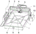
Fig. 1 is a schematic view of the overall structure of the present invention.
Fig. 2 is the schematic structural diagram of the edge grinding device of the present invention.
Fig. 3 is a schematic structural view of the knife grinder of the present invention.
In the drawings, the components represented by the respective reference numerals are listed below:
a lathe bed 1; a transverse bracket 2; a first drive device 3; a second drive device 4; an edge grinding device 5; a mounting frame 51; a servo motor 52; a water pump 53; a main shaft 54; sharpening 55; mounting threads 551; a grinding head 552; a keyway 553; a drive gear 56; a driven gear 57; a universal tube 58; a shower head 59; a suction cup holder 6; a suction cup 7; a vacuum pump 8; a wastewater outlet 9; a water tank 10; a water pipe 11.
Detailed Description
The invention will be further described with reference to specific examples, which are intended to be illustrative only and not to limit the scope of the invention. Furthermore, it should be understood that various changes and modifications of the present invention may be made by those skilled in the art after reading the teachings of the present invention, and such equivalents also fall within the scope of the appended claims.
Referring to fig. 1 to 3, the utility model is a schematic diagram of the overall structure, a schematic diagram of an edging device 5, and a schematic diagram of a sharpening 55 structure, and includes a bed 1, a first driving device 3, a second driving device 4, a transverse bracket 2, a suction cup 7 device, and an edging device 5, wherein the transverse bracket 2 is transversely disposed above the bed 1, the transverse bracket 2 is slidably connected with the bed 1, the edging device 5 is disposed on the transverse bracket 2, the edging device 5 is slidably connected with the transverse bracket 2, and the bed 1 is provided with the suction cup 7 device;
the transverse support 2 is driven by a first driving device 3 to reciprocate on the bed body 1, and the edge grinding device 5 is driven by a second driving device 4 to reciprocate on the transverse support 2;
the sucking disc 7 device comprises a sucking disc frame 6, sucking discs 7 and a vacuum pump 8, the sucking disc frame 6 is fixed on the lathe bed 1, the sucking disc frame 6 is provided with a plurality of sucking discs 7, the vacuum pump 8 is arranged in the lathe bed 1, and the vacuum pump 8 is communicated with the sucking discs 7 through an air pipe;
The periphery of the lathe bed 1 is provided with a baffle plate, the height of the baffle plate is higher than the horizontal height of the sucker 7, the upper side surface of the lathe bed 1 is provided with a wastewater outlet 9, a water inlet of the water pump 53 is communicated with the bottom of the water tank 10 through a water pipe 11, one side of the lathe bed 1 is provided with the water tank 10, the side surface of the lathe bed 1 is provided with a control console, and the first driving device 3, the second driving device 4, the vacuum pump 8 and the water pump 53 are all electrically.
The utility model provides a sharpedge 55, includes installation screw 551, bistrique, keyway 553, sharpedge 55 one side is provided with installation screw 551, sharpedge 55 opposite side is provided with the bistrique, sharpedge 55 and be provided with keyway 553 between the installation screw 551, the bistrique is the round platform body, the side of round platform body is the mill face, the angle of round platform body generating line includes thirty degrees.
Use the utility model discloses the time, install thirty degrees whets a knife 55 on main shaft 54, place the glass level on sucking disc frame 6, open vacuum pump 8 through the control cabinet, sucking disc 7 negative pressure increases, glass adsorbs on sucking disc 7, open the motor through the control cabinet, the motor drives main shaft 54 and whets a knife 55 rotation, gear drive water pump 53 on the main shaft 54 carries out work, start first drive arrangement 3 through the control cabinet, second drive arrangement 4, drive arrangement control edging device 5 removes in the work area top, carry out the edging to glass, cut edge and close vacuum pump 8 after accomplishing, take off glass, accomplish the edging processing to glass.
When using the utility model discloses when needing forty-five degrees edging to glass, it is the 55 that sharpen knives of forty-five degrees to change the generating line, carries out the edging processing to glass.
The utility model discloses a glass edging machine, through sucking disc 7, vacuum pump 8, place glass at the processing bench, vacuum pump 8 breathes in, make glass fix on sucking disc 7, can avoid glass to put on firm workstation and wearing and tearing appear, make the motor drive main shaft 54 simultaneously through setting up the gear, water pump 53 is rotatory, reduce equipment cost and manufacturing cost, the 55 angle modulation that whets a knife through changing different angles, compare the reliable accuracy that uses the mill more, through being provided with first drive arrangement 33, second drive arrangement 4 can make edging device 5 remove wantonly in the regional top that needs work, carry out edging processing to special-shaped glass.
The above description is only for the preferred embodiment of the present invention, and should not be construed as limiting the present invention, and any modifications, equivalent replacements, improvements, etc. made within the spirit and principle of the present invention should be included within the protection scope of the present invention.
Claims (6)
1. An edging machine for glass production, characterized by comprising: the edge grinding device is arranged on the transverse support and is in sliding connection with the transverse support, and the sucking disc device is arranged on the lathe bed;
the transverse support is driven by a first driving device to reciprocate on the machine body, and the edge grinding device is driven by a second driving device to reciprocate on the transverse support;
the sucking disc device comprises a sucking disc frame, sucking discs and a vacuum pump, wherein the sucking disc frame is fixed on the lathe bed, a plurality of sucking discs are arranged on the sucking disc frame, the vacuum pump is arranged in the lathe bed, and the vacuum pump is communicated with the sucking discs through an air pipe;
the edging device includes mounting bracket, servo motor, main shaft, water pump, shower nozzle, driving gear, driven gear, whet a knife, the mounting bracket with horizontal support sliding connection, servo motor passes through bolt longitudinal fixation on the mounting bracket, the last driven connection of servo motor has the main shaft, the main shaft below is provided with the screw hole, install the whet a knife through the screw thread on the main shaft, be provided with the driving gear on the main shaft, the servo motor right side vertically is provided with the water pump, the water pump passes through bolted connection and fixes on the mounting bracket, the universal pipe is installed to the water pump delivery port, install the shower nozzle on the universal pipe, the water pump input is provided with driven gear, the driving gear with the driven gear cooperation.
2. An edging machine for glass production according to claim 1, characterized in that: and the periphery of the lathe bed is provided with a baffle plate, and the height of the baffle plate is higher than the horizontal height of the sucking disc.
3. An edging machine for glass production according to claim 1, characterized in that: and a wastewater outlet is formed in the upper side surface of the bed body.
4. An edging machine for glass production according to claim 1, characterized in that: the water inlet of the water pump is communicated with the bottom of the water tank through a water pipe, and the water tank is arranged on one side of the lathe bed.
5. An edging machine for glass production according to claim 1, characterized in that: the side face of the lathe bed is provided with a control console, and the first driving device, the second driving device, the vacuum pump and the water pump are all electrically connected with the control console.
6. An edging machine for glass production according to claim 1, characterized in that: the grinding head is arranged on the other side of the knife, a key groove is formed between the knife and the mounting thread, the grinding head is a circular truncated cone, the side face of the circular truncated cone is a grinding face, and the angle of a bus of the circular truncated cone comprises thirty degrees.
Priority Applications (1)
| Application Number | Priority Date | Filing Date | Title |
|---|---|---|---|
| CN202020669019.6U CN212145777U (en) | 2020-04-28 | 2020-04-28 | A edging machine for glass production |
Applications Claiming Priority (1)
| Application Number | Priority Date | Filing Date | Title |
|---|---|---|---|
| CN202020669019.6U CN212145777U (en) | 2020-04-28 | 2020-04-28 | A edging machine for glass production |
Publications (1)
| Publication Number | Publication Date |
|---|---|
| CN212145777U true CN212145777U (en) | 2020-12-15 |
Family
ID=73720997
Family Applications (1)
| Application Number | Title | Priority Date | Filing Date |
|---|---|---|---|
| CN202020669019.6U Active CN212145777U (en) | 2020-04-28 | 2020-04-28 | A edging machine for glass production |
Country Status (1)
| Country | Link |
|---|---|
| CN (1) | CN212145777U (en) |
Cited By (2)
| Publication number | Priority date | Publication date | Assignee | Title |
|---|---|---|---|---|
| CN115042044A (en) * | 2022-05-25 | 2022-09-13 | 涡阳县高炉创新包装有限责任公司 | Glass production is with glass side grinding device |
| CN116423331A (en) * | 2023-06-14 | 2023-07-14 | 河北德航玻璃制品有限公司 | Automatic conveying edge grinding machine for toughened glass |
-
2020
- 2020-04-28 CN CN202020669019.6U patent/CN212145777U/en active Active
Cited By (4)
| Publication number | Priority date | Publication date | Assignee | Title |
|---|---|---|---|---|
| CN115042044A (en) * | 2022-05-25 | 2022-09-13 | 涡阳县高炉创新包装有限责任公司 | Glass production is with glass side grinding device |
| CN115042044B (en) * | 2022-05-25 | 2023-11-24 | 涡阳县高炉创新包装有限责任公司 | Glass side grinding device for glass production |
| CN116423331A (en) * | 2023-06-14 | 2023-07-14 | 河北德航玻璃制品有限公司 | Automatic conveying edge grinding machine for toughened glass |
| CN116423331B (en) * | 2023-06-14 | 2023-08-11 | 河北德航玻璃制品有限公司 | Automatic conveying edge grinding machine for toughened glass |
Similar Documents
| Publication | Publication Date | Title |
|---|---|---|
| CN212145777U (en) | A edging machine for glass production | |
| CN111958341A (en) | Cylinder timber surrounding type grinding device | |
| CN202097612U (en) | Tool sharpener | |
| CN207223566U (en) | A kind of cylinder blade face grinding device | |
| CN215999838U (en) | Edge and corner polishing device convenient for angle adjustment for hardware machining | |
| CN115972012A (en) | Panel polisher | |
| CN113910042B (en) | Dysmorphism backlight board cutting edging all-in-one | |
| CN113263367A (en) | Full-automatic numerical control cylindrical grinder | |
| CN113996872B (en) | Gear grinding machine for gear machining and gear grinding method thereof | |
| CN211760334U (en) | Hardware plate polishing device convenient for chip removal | |
| CN113560968A (en) | Manufacturing process and production line for automatic cutting edge of cutter by using robot technology | |
| CN113681359A (en) | Reciprocating type blade material sharpener for cutting device | |
| CN217143321U (en) | Internal grinding machine convenient to clearance abrasive dust | |
| CN217860413U (en) | Deburring device for plate processing | |
| CN211361688U (en) | Grinding device for sheet metal working | |
| CN220825732U (en) | Knife grinder with high safety | |
| CN218254308U (en) | Burr polishing equipment | |
| CN220427756U (en) | Surface grinder with chip removing function for workpiece processing | |
| CN217413550U (en) | Grinding tool for glass engraving and processing | |
| CN210678091U (en) | Surface deburring device for building board | |
| CN220533716U (en) | Efficient grinding and processing device for cutter | |
| CN216179187U (en) | Full-automatic shaped glass edging device | |
| CN211760449U (en) | Production of biconvex lens is with two side milling device | |
| CN212240438U (en) | Grinding device is used in metal material production | |
| CN219924776U (en) | Machining grinding device |
Legal Events
| Date | Code | Title | Description |
|---|---|---|---|
| GR01 | Patent grant | ||
| GR01 | Patent grant |