CN113681359A - Reciprocating type blade material sharpener for cutting device - Google Patents
Reciprocating type blade material sharpener for cutting device Download PDFInfo
- Publication number
- CN113681359A CN113681359A CN202110989669.8A CN202110989669A CN113681359A CN 113681359 A CN113681359 A CN 113681359A CN 202110989669 A CN202110989669 A CN 202110989669A CN 113681359 A CN113681359 A CN 113681359A
- Authority
- CN
- China
- Prior art keywords
- sharpener
- cutting device
- workbench
- frame
- blade material
- Prior art date
- Legal status (The legal status is an assumption and is not a legal conclusion. Google has not performed a legal analysis and makes no representation as to the accuracy of the status listed.)
- Pending
Links
Images


Classifications
-
- B—PERFORMING OPERATIONS; TRANSPORTING
- B24—GRINDING; POLISHING
- B24B—MACHINES, DEVICES, OR PROCESSES FOR GRINDING OR POLISHING; DRESSING OR CONDITIONING OF ABRADING SURFACES; FEEDING OF GRINDING, POLISHING, OR LAPPING AGENTS
- B24B3/00—Sharpening cutting edges, e.g. of tools; Accessories therefor, e.g. for holding the tools
- B24B3/36—Sharpening cutting edges, e.g. of tools; Accessories therefor, e.g. for holding the tools of cutting blades
- B24B3/361—Sharpening cutting edges, e.g. of tools; Accessories therefor, e.g. for holding the tools of cutting blades of reciprocating blades
-
- B—PERFORMING OPERATIONS; TRANSPORTING
- B24—GRINDING; POLISHING
- B24B—MACHINES, DEVICES, OR PROCESSES FOR GRINDING OR POLISHING; DRESSING OR CONDITIONING OF ABRADING SURFACES; FEEDING OF GRINDING, POLISHING, OR LAPPING AGENTS
- B24B41/00—Component parts such as frames, beds, carriages, headstocks
- B24B41/02—Frames; Beds; Carriages
-
- B—PERFORMING OPERATIONS; TRANSPORTING
- B24—GRINDING; POLISHING
- B24B—MACHINES, DEVICES, OR PROCESSES FOR GRINDING OR POLISHING; DRESSING OR CONDITIONING OF ABRADING SURFACES; FEEDING OF GRINDING, POLISHING, OR LAPPING AGENTS
- B24B41/00—Component parts such as frames, beds, carriages, headstocks
- B24B41/04—Headstocks; Working-spindles; Features relating thereto
-
- B—PERFORMING OPERATIONS; TRANSPORTING
- B24—GRINDING; POLISHING
- B24B—MACHINES, DEVICES, OR PROCESSES FOR GRINDING OR POLISHING; DRESSING OR CONDITIONING OF ABRADING SURFACES; FEEDING OF GRINDING, POLISHING, OR LAPPING AGENTS
- B24B41/00—Component parts such as frames, beds, carriages, headstocks
- B24B41/06—Work supports, e.g. adjustable steadies
-
- B—PERFORMING OPERATIONS; TRANSPORTING
- B24—GRINDING; POLISHING
- B24B—MACHINES, DEVICES, OR PROCESSES FOR GRINDING OR POLISHING; DRESSING OR CONDITIONING OF ABRADING SURFACES; FEEDING OF GRINDING, POLISHING, OR LAPPING AGENTS
- B24B47/00—Drives or gearings; Equipment therefor
-
- B—PERFORMING OPERATIONS; TRANSPORTING
- B24—GRINDING; POLISHING
- B24B—MACHINES, DEVICES, OR PROCESSES FOR GRINDING OR POLISHING; DRESSING OR CONDITIONING OF ABRADING SURFACES; FEEDING OF GRINDING, POLISHING, OR LAPPING AGENTS
- B24B47/00—Drives or gearings; Equipment therefor
- B24B47/02—Drives or gearings; Equipment therefor for performing a reciprocating movement of carriages or work- tables
- B24B47/04—Drives or gearings; Equipment therefor for performing a reciprocating movement of carriages or work- tables by mechanical gearing only
-
- B—PERFORMING OPERATIONS; TRANSPORTING
- B24—GRINDING; POLISHING
- B24B—MACHINES, DEVICES, OR PROCESSES FOR GRINDING OR POLISHING; DRESSING OR CONDITIONING OF ABRADING SURFACES; FEEDING OF GRINDING, POLISHING, OR LAPPING AGENTS
- B24B47/00—Drives or gearings; Equipment therefor
- B24B47/10—Drives or gearings; Equipment therefor for rotating or reciprocating working-spindles carrying grinding wheels or workpieces
- B24B47/12—Drives or gearings; Equipment therefor for rotating or reciprocating working-spindles carrying grinding wheels or workpieces by mechanical gearing or electric power
Landscapes
- Engineering & Computer Science (AREA)
- Mechanical Engineering (AREA)
- Finish Polishing, Edge Sharpening, And Grinding By Specific Grinding Devices (AREA)
Abstract
The invention discloses a knife sharpener for a reciprocating type blade material cutting device, which comprises a frame, wherein a workbench is welded at the top of the frame, a groove is formed in the surface of the top of the workbench, a portal frame is welded at one side of the top of the workbench, an electric telescopic rod is fixedly installed at the top of the portal frame, the output end of the bottom of the electric telescopic rod penetrates through the top of the portal frame and is fixedly connected with the top of a disc motor, a servo motor drives a speed reducer and a screw rod to rotate, the screw rod rotates to enable a rotating nut to move back and forth on the screw rod, the workbench can move directionally on a sliding rail, a cutting blade is enabled to move to the bottom of the portal frame, the electric telescopic rod is started to enable the disc motor to move up and down, the knife sharpener is flexible to operate, a sharpening disc is positioned on the surface of the bottom of a edging gear, an edging gear is arranged to facilitate sharpening of a convex block on the surface of the cutting blade, the loss of the grinding disc is reduced, so that the cutting blade is more efficient to grind.
Description
Technical Field
The invention belongs to the technical field of knife sharpeners, and particularly relates to a knife sharpener for a reciprocating type blade material cutting device.
Background
The cutter includes a reciprocating knife driven by an eccentric mechanism. The knife is made as a one-piece member having a lower cutting portion supported by a guide for reciprocating movement along a vertical guide axis, and an upper resiliently flexible drive portion connected to a drive mechanism. The drive portion is bent laterally in a plane perpendicular to the drive axis of the eccentric mechanism, which allows the tool to reciprocate along a vertical guide axis. A disadvantage of this cutter is that a long and flexible blade is required.
However, in this case, the knife is rigid and driven by a linkage connecting the top of the knife to an eccentric drive. The inclusion of additional linkages and their associated hardware between the drive and knife results in a bulky, relatively heavy device that cannot operate efficiently at high speeds. Moreover, the large number of moving parts present in such devices requires constant maintenance, and therefore, the cutters are susceptible to roll marks and bulges.
To this end, we propose a reciprocating blade material cutting device with a knife sharpener to solve the problems of the prior art.
Disclosure of Invention
The present invention is directed to a knife sharpener for a reciprocating blade material cutting device to solve the above-mentioned problems of the prior art.
In order to achieve the purpose, the invention adopts the following technical scheme:
a knife sharpener for a reciprocating blade material cutting device comprises a frame, wherein a workbench is welded at the top of the frame, a groove is formed in the surface of the top of the workbench, a portal frame is welded on one side of the top of the workbench, an electric telescopic rod is fixedly installed at the top of the portal frame, the output end of the bottom of the electric telescopic rod penetrates through the top of the portal frame and is fixedly connected with the top of a disc motor, the output shaft of the bottom of the disc motor is in transmission connection with the internal input end of a polishing mechanism, a lead screw is rotatably connected inside the groove, a speed reducer is fixedly installed at the opening at one end of the groove through a fixing seat, a servo motor is installed at one end, away from the frame, of the speed reducer, the output shaft of the servo motor is in transmission connection with the input shaft of the speed reducer, and the output shaft of the speed reducer is fixedly connected with the input end of the lead screw, the lead screw on mutual symmetry rotate and be connected with two sets of rotating nut, the mutual symmetrical welding in surface of frame have two sets of slide rails, the top sliding connection of slide rail have a year thing board, the top of rotating nut pass through the connecting rod with the bottom fixed connection who carries the thing board, the thing board of carrying on install pneumatic clamping mechanism.
Preferably: the pneumatic clamping mechanism comprises a fixed plate, air cylinder assemblies, a push plate and a baffle plate, wherein the fixed plate is welded at one end of the top of the workbench, two groups of air cylinder assemblies are symmetrically welded at the outer side of the fixed plate, piston rods of the air cylinder assemblies penetrate through the inside of the fixed plate and are fixedly connected with the input end of the push plate, and the baffle plate is welded at the other end of the top of the workbench.
Preferably: the air cylinder assembly comprises a mounting frame, a push plate and an air cylinder, the mounting frame is fixedly connected with the fixed plate, the air cylinder is fixedly mounted at one end, far away from the fixed plate, of the mounting frame, the push plate is connected to the inside of the mounting frame in a sliding mode, and a piston rod of the air cylinder penetrates through one end of the mounting frame and is in transmission connection with an input shaft of the push plate.
Preferably: one side of portal frame be equipped with waste collector, waste collector include casing, vacuum pump, air inlet fill, waste recovery groove, handle and spout, one side of casing install the vacuum pump, the positive fixed mounting of casing have the air inlet fill, the inside bottom welding of casing have the spout, the inside sliding connection of spout have waste recovery groove, waste recovery groove's one end run through in the one end bottom of casing with the one end fixed connection of handle.
Preferably: grinding machanism include edging gear and the dish of polishing, the dish of polishing be located the bottom surface of edging gear.
Preferably: the bottom landing leg department of frame all install anti-skidding rubber stabilizer blade.
Preferably: the type of the servo motor is MD 330; the model of the speed reducer is WPWEDKA 50-600-B; the model of the electric telescopic rod is SMC-MHY 2-20D; the disc type motor is M5120-50.
Preferably: the top surface of the slide rail is electroplated with a metal titanium layer.
The invention has the technical effects and advantages that: compared with the prior art, the knife sharpener for the reciprocating type blade material cutting device is characterized in that a servo motor is started, the servo motor drives a speed reducer to rotate, the speed reducer drives a screw rod to rotate, the screw rod rotates to enable a rotating nut to move back and forth on the screw rod, a workbench can move on a sliding rail in a directional mode, a cutting blade is enabled to move to the bottom of a portal frame, an electric telescopic rod is started to enable a disc type motor to move up and down, the knife sharpener is flexible to operate, a sharpening disc is located on the bottom surface of the edging gear, the edging gear is arranged, protruding blocks on the surface of the cutting blade can be conveniently sharpened, loss of the sharpening disc is reduced, and the sharpening of the cutting blade is enabled to be more efficient.
Drawings
FIG. 1 is a schematic structural view of the present invention;
FIG. 2 is a schematic bottom view of the polishing mechanism of the present invention;
FIG. 3 is a sectional view of the inner structure of the working table of the present invention;
FIG. 4 is a schematic view of the waste collector of the present invention;
FIG. 5 is a cross-sectional view of a waste collector of the present invention;
FIG. 6 is a structural cross-sectional view of a cylinder assembly of the present invention
In the figure: 1. a frame; 2. a servo motor; 3. a speed reducer; 4. a fixed seat; 5. a work table; 6. a groove; 7. a screw rod; 8. a slide rail; 9. a loading plate; 10. a pneumatic clamping mechanism; 101. a fixing plate; 102. a cylinder assembly; 1021. a mounting frame; 1022. pushing the plate; 1023. a cylinder; 103. pushing the plate; 104. a baffle plate; 11. rotating the nut; 12. a connecting rod; 13. a gantry; 14. an electric telescopic rod; 15. a waste collector; 151. a housing; 152. a vacuum pump; 153. an air inlet hopper; 154. a waste recovery tank; 155. a handle; 156. a chute; 16. a disc motor; 17. a polishing mechanism; 171. edging the gear; 172. grinding disc; 18. anti-skid rubber support legs.
Detailed Description
The technical solutions in the embodiments of the present invention will be clearly and completely described below with reference to the drawings in the embodiments of the present invention, and it is obvious that the described embodiments are only a part of the embodiments of the present invention, and not all of the embodiments. The specific embodiments described herein are merely illustrative of the invention and do not delimit the invention. All other embodiments, which can be derived by a person skilled in the art from the embodiments given herein without making any creative effort, shall fall within the protection scope of the present invention.
Examples
The invention provides a knife sharpener for a reciprocating blade material cutting device as shown in figures 1-6, which comprises a stander 1, wherein the top of the stander 1 is welded with a workbench 5, the top surface of the workbench 5 is provided with a groove 6, one side of the top of the workbench 5 is welded with a portal frame 13, the top of the portal frame 13 is fixedly provided with an electric telescopic rod 14, the bottom output end of the electric telescopic rod 14 penetrates through the top of the portal frame 13 and is fixedly connected with the top of a disc type motor 16, the bottom output shaft of the disc type motor 16 is in transmission connection with the internal input end of a grinding mechanism 17, the inside of the groove 6 is rotatably connected with a screw rod 7, an opening at one end of the groove 6 is fixedly provided with a speed reducer 3 through a fixed seat 4, one end of the speed reducer 3, which is far away from the stander 1, is provided with a servo motor 2, the output shaft of the servo motor 2 is in transmission connection with the input shaft of the speed reducer 3, the output shaft of the speed reducer 3 is fixedly connected with the input end of the screw rod 7, the screw rod 7 is connected with two sets of rotating nuts 11 in a mutually symmetrical and rotating mode, the surface of the rack 1 is welded with two sets of sliding rails 8 in a mutually symmetrical mode, the top of each sliding rail 8 is connected with a loading plate 9 in a sliding mode, the top end of each rotating nut 11 is fixedly connected with the bottom of each loading plate 9 through a connecting rod 12, and each loading plate 9 is provided with a pneumatic clamping mechanism 10.
In the embodiment of the present invention, specifically: the pneumatic clamping mechanism 10 comprises a fixed plate 101, cylinder assemblies 102, a push plate 103 and a baffle plate 104, wherein the fixed plate 101 is welded at one end of the top of the workbench 5, two groups of cylinder assemblies 102 are symmetrically welded at the outer sides of the fixed plate 101, a piston rod of each cylinder assembly 102 penetrates through the inside of the fixed plate 101 and is fixedly connected with the input end of the push plate 103, and the baffle plate 104 is welded at the other end of the top of the workbench 5.
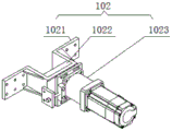
In the embodiment of the present invention, specifically: the cylinder assembly 102 comprises a mounting frame 1021, a push plate 1022 and a cylinder 1023, the mounting frame 1021 is fixedly connected with the fixing plate 101, one end of the mounting frame 1021, which is far away from the fixing plate 101, is fixedly provided with a cylinder 1023, the mounting frame 1021 is connected with the push plate 1022 in an internal sliding manner, a piston rod of the cylinder 1023 penetrates through one end of the mounting frame 1021 and is in transmission connection with an input shaft of the push plate 1022, the cylinder assembly 102 is TN25X30S in model, the cylinder 1023 is started to push the push plate 1022, and the push plate 1022 drives a cutting blade to polish and push.
In the embodiment of the present invention, specifically: portal frame 13 one side be equipped with waste collector 15, waste collector 15 include casing 151, vacuum pump 152, air inlet fill 153, waste recycling groove 154, handle 155 and spout 156, one side of casing 151 install vacuum pump 152, the positive fixed mounting of casing 151 have air inlet fill 153, the inside bottom welding of casing 151 have spout 156, the inside sliding connection of spout 156 have waste recycling groove 154, waste recycling groove 154 one end run through in casing 151 one end bottom with handle 155 one end fixed connection, start vacuum pump 152 for the inside vacuum negative pressure that produces of casing 151, and then the waste material after polishing can enter into the inside waste recycling groove 154 of casing 151 through air inlet fill 153 and collect.
In the embodiment of the present invention, specifically: grinding machanism 17 include edging gear 171 and polishing dish 172, polishing dish 172 be located edging gear 171's bottom surface, set up edging gear 171, be convenient for polish the surperficial protruding piece of blade and turn-up, reduce the loss of polishing dish 172.
In the embodiment of the present invention, specifically: the bottom landing leg department of frame 1 all install anti-skidding rubber stabilizer blade 18, be equipped with adjusting bolt on setting up anti-skidding rubber stabilizer blade 18, be convenient for adjust the device's levelness, simultaneously, play the skid-proof effect of shock attenuation.
In the embodiment of the present invention, specifically: the type of the servo motor 2 is MD 330; the model of the speed reducer 3 is WPWEDKA 50-600-B; the model of the electric telescopic rod 14 is SMC-MHY 2-20D; the disc type motor 16 is M5120-50.
In the embodiment of the present invention, specifically: the top surface of the slide rail 8 is electroplated with a metal titanium layer, which is convenient for the anti-slip effect of the slide rail 8 and improves the service life of the slide rail 8.
Working principle or structural principle: through anti-skidding rubber stabilizer blade 18, play the skid-proof effect of shock attenuation, be equipped with adjusting bolt on the anti-skidding rubber stabilizer blade 18, be convenient for adjust the device's levelness, place the top of workstation 5 with cutting blade, align, start the cylinder assembly 102 of pneumatic clamping mechanism 10, drive the mating reaction of push pedal 103 and baffle 104, press from both sides cutting blade fixed fastening, start servo motor 2, servo motor 2 drives speed reducer 3 and rotates, speed reducer 3 drives lead screw 7 and rotates, lead screw 7 rotates and makes swivel nut 11 can be on lead screw 7 back-and-forth movement, and then make workstation 5 can be on slide rail 8 directional removal, make cutting blade remove the bottom of portal frame 13, start electric telescopic handle 14 and make disc motor 16 upper and lower displacement, start disc motor 16 and drive grinding machanism 17 and polish the cutting blade.
Finally, it should be noted that: although the present invention has been described in detail with reference to the foregoing embodiments, it will be apparent to those skilled in the art that modifications may be made to the embodiments or portions thereof without departing from the spirit and scope of the invention.
Claims (8)
1. The utility model provides a reciprocating type blade material sharpener for cutting device, includes frame (1), its characterized in that: the top of the rack (1) is welded with the workbench (5), the top surface of the workbench (5) is provided with a groove (6), one side of the top of the workbench (5) is welded with a portal frame (13), the top of the portal frame (13) is fixedly provided with an electric telescopic rod (14), the bottom output end of the electric telescopic rod (14) penetrates through the top of the portal frame (13) and is fixedly connected with the top of a disc motor (16), the bottom output shaft of the disc motor (16) is in transmission connection with the internal input end of a polishing mechanism (17), the groove (6) is rotatably connected with a screw rod (7), an opening at one end of the groove (6) is fixedly provided with a speed reducer (3) through a fixing seat (4), one end of the speed reducer (3) far away from the rack (1) is provided with a servo motor (2), the output shaft of servo motor (2) with the input shaft transmission of speed reducer (3) be connected, the output shaft of speed reducer (3) and the input fixed connection of lead screw (7), lead screw (7) on each other the symmetry rotation be connected with two sets of rotating nut (11), the mutual symmetrical welding in surface of frame (1) have two sets of slide rails (8), the top sliding connection of slide rail (8) carry thing board (9), the top of rotating nut (11) pass through connecting rod (12) with the bottom fixed connection of carrying thing board (9), carry and install pneumatic clamping mechanism (10) on thing board (9).
2. The sharpener of claim 1 wherein said blade is a reciprocating blade material cutting device, said sharpener further comprising: the pneumatic clamping mechanism (10) comprises a fixing plate (101), a cylinder assembly (102), a push plate (103) and a baffle plate (104), wherein the fixing plate (101) is welded at one end of the top of the workbench (5), two groups of cylinder assemblies (102) are symmetrically welded at the outer side of the fixing plate (101), a piston rod of each cylinder assembly (102) penetrates through the inside of the fixing plate (101) and is fixedly connected with the input end of the push plate (103), and the baffle plate (104) is welded at the other end of the top of the workbench (5).
3. The sharpener of claim 2 for a reciprocating blade material cutting device, wherein: the cylinder component (102) comprises a mounting frame (1021), a push plate (1022) and a cylinder (1023), the mounting frame (1021) is fixedly connected with the fixing plate (101), the end, far away from the fixing plate (101), of the mounting frame (1021) is fixedly provided with the cylinder (1023), the push plate (1022) is connected with the mounting frame (1021) in a sliding mode, and a piston rod of the cylinder (1023) penetrates through one end of the mounting frame (1021) and is in transmission connection with an input shaft of the push plate (1022).
4. The sharpener of claim 1 wherein said blade is a reciprocating blade material cutting device, said sharpener further comprising: one side of portal frame (13) be equipped with waste collector (15), waste collector (15) including casing (151), vacuum pump (152), air inlet fill (153), waste recycling groove (154), handle (155) and spout (156), one side of casing (151) install vacuum pump (152), the front fixed mounting of casing (151) have air inlet fill (153), the inside bottom welding of casing (151) have spout (156), the inside sliding connection of spout (156) have waste recycling groove (154), the one end of waste recycling groove (154) run through in the one end bottom of casing (151) with the one end fixed connection of handle (155).
5. The sharpener of claim 1 wherein said blade is a reciprocating blade material cutting device, said sharpener further comprising: grinding machanism (17) including edging gear (171) and polishing dish (172), polishing dish (172) be located the bottom surface of edging gear (171).
6. The sharpener of claim 1 wherein said blade is a reciprocating blade material cutting device, said sharpener further comprising: the bottom supporting legs of the frame (1) are provided with anti-skid rubber supporting feet (18).
7. The sharpener of claim 1 wherein said blade is a reciprocating blade material cutting device, said sharpener further comprising: the type of the servo motor (2) is MD 330; the model of the speed reducer (3) is WPWEDKA 50-600-B; the model of the electric telescopic rod (14) is SMC-MHY 2-20D; the disc type motor (16) is M5120-50 in model.
8. The sharpener of claim 1 wherein said blade is a reciprocating blade material cutting device, said sharpener further comprising: the top surface of the sliding rail (8) is electroplated with a metal titanium layer.
Priority Applications (1)
| Application Number | Priority Date | Filing Date | Title |
|---|---|---|---|
| CN202110989669.8A CN113681359A (en) | 2021-08-26 | 2021-08-26 | Reciprocating type blade material sharpener for cutting device |
Applications Claiming Priority (1)
| Application Number | Priority Date | Filing Date | Title |
|---|---|---|---|
| CN202110989669.8A CN113681359A (en) | 2021-08-26 | 2021-08-26 | Reciprocating type blade material sharpener for cutting device |
Publications (1)
| Publication Number | Publication Date |
|---|---|
| CN113681359A true CN113681359A (en) | 2021-11-23 |
Family
ID=78583039
Family Applications (1)
| Application Number | Title | Priority Date | Filing Date |
|---|---|---|---|
| CN202110989669.8A Pending CN113681359A (en) | 2021-08-26 | 2021-08-26 | Reciprocating type blade material sharpener for cutting device |
Country Status (1)
| Country | Link |
|---|---|
| CN (1) | CN113681359A (en) |
Cited By (1)
| Publication number | Priority date | Publication date | Assignee | Title |
|---|---|---|---|---|
| CN114559326A (en) * | 2022-03-01 | 2022-05-31 | 广东旭业光电科技股份有限公司 | Lens edge grinding device for mobile phone lens |
Citations (6)
| Publication number | Priority date | Publication date | Assignee | Title |
|---|---|---|---|---|
| KR101531623B1 (en) * | 2014-01-17 | 2015-06-25 | 태일실업 주식회사 | A Saw Blade Automatic Grinding Apparatus |
| CN108856806A (en) * | 2018-08-14 | 2018-11-23 | 国胜科技(惠州)有限公司 | A kind of damping site construction steel tube surface drilling equipment |
| CN109015169A (en) * | 2018-08-12 | 2018-12-18 | 惠州市豪美氏智能电气有限公司 | A kind of machining metallic conduit notch burr polishing device |
| CN109015289A (en) * | 2018-10-15 | 2018-12-18 | 苗改燕 | A kind of high-efficiency and precision type horizontal processing machine tool |
| CN208601202U (en) * | 2018-08-06 | 2019-03-15 | 佛山市铭诚铝制品有限公司 | A kind of aluminium sheet grinding device convenient for adjusting angle |
| CN109986419A (en) * | 2019-03-27 | 2019-07-09 | 安徽省天坛重工机床制造有限公司 | A kind of grinding device for shear rounding machine cutter |
-
2021
- 2021-08-26 CN CN202110989669.8A patent/CN113681359A/en active Pending
Patent Citations (6)
| Publication number | Priority date | Publication date | Assignee | Title |
|---|---|---|---|---|
| KR101531623B1 (en) * | 2014-01-17 | 2015-06-25 | 태일실업 주식회사 | A Saw Blade Automatic Grinding Apparatus |
| CN208601202U (en) * | 2018-08-06 | 2019-03-15 | 佛山市铭诚铝制品有限公司 | A kind of aluminium sheet grinding device convenient for adjusting angle |
| CN109015169A (en) * | 2018-08-12 | 2018-12-18 | 惠州市豪美氏智能电气有限公司 | A kind of machining metallic conduit notch burr polishing device |
| CN108856806A (en) * | 2018-08-14 | 2018-11-23 | 国胜科技(惠州)有限公司 | A kind of damping site construction steel tube surface drilling equipment |
| CN109015289A (en) * | 2018-10-15 | 2018-12-18 | 苗改燕 | A kind of high-efficiency and precision type horizontal processing machine tool |
| CN109986419A (en) * | 2019-03-27 | 2019-07-09 | 安徽省天坛重工机床制造有限公司 | A kind of grinding device for shear rounding machine cutter |
Cited By (1)
| Publication number | Priority date | Publication date | Assignee | Title |
|---|---|---|---|---|
| CN114559326A (en) * | 2022-03-01 | 2022-05-31 | 广东旭业光电科技股份有限公司 | Lens edge grinding device for mobile phone lens |
Similar Documents
| Publication | Publication Date | Title |
|---|---|---|
| CN113681359A (en) | Reciprocating type blade material sharpener for cutting device | |
| CN111805338A (en) | Grinding device for machine case cutting edge | |
| CN205968523U (en) | Glass board grinding device | |
| CN201702619U (en) | Knife sharpener | |
| CN218746778U (en) | Lens sheet copying machine | |
| CN114193267B (en) | Equipment for removing burrs on inner surface and outer surface of spring and working method thereof | |
| CN113414664B (en) | Rear skirt plate polishing equipment in rear skirt plate welding assembly and working method thereof | |
| CN214603431U (en) | Polishing device for cylindrical rod body | |
| CN212264423U (en) | Mechanical forging equipment with fixed transportation product | |
| CN213136261U (en) | External grinding device for forged piece | |
| CN211073008U (en) | Water-cooled wall band steel is polished and school shape equipment | |
| CN211760334U (en) | Hardware plate polishing device convenient for chip removal | |
| CN114434163A (en) | Grinding device is cut to sheet metal limit end burr | |
| CN209970836U (en) | Swing arm overhead type circular saw cutting rice noodle device | |
| CN219987762U (en) | Slotting device for foam pad production | |
| CN214418378U (en) | Deburring device for inner surface of bearing | |
| CN217317222U (en) | Vertical small-size electric knife grinder | |
| CN218397538U (en) | Burnishing device is used in centrifugal pump processing | |
| CN218017488U (en) | Dust-proof device of surface grinding machine | |
| CN214489597U (en) | Bicycle chain burr cutting device | |
| CN215659719U (en) | Horizontal-axis-distance table surface grinding machine | |
| CN204658102U (en) | A kind of knife sharpener for blade of keeping straight on | |
| CN216371421U (en) | Stone rough grinding machine | |
| CN219504401U (en) | Grinding machine for machining center | |
| CN209754753U (en) | Be used for kitchen knife blank grinding device |
Legal Events
| Date | Code | Title | Description |
|---|---|---|---|
| PB01 | Publication | ||
| PB01 | Publication | ||
| SE01 | Entry into force of request for substantive examination | ||
| SE01 | Entry into force of request for substantive examination | ||
| RJ01 | Rejection of invention patent application after publication | ||
| RJ01 | Rejection of invention patent application after publication |
Application publication date: 20211123 |