CN212106016U - Engine tail gas purification device - Google Patents
Engine tail gas purification device Download PDFInfo
- Publication number
- CN212106016U CN212106016U CN202020690546.5U CN202020690546U CN212106016U CN 212106016 U CN212106016 U CN 212106016U CN 202020690546 U CN202020690546 U CN 202020690546U CN 212106016 U CN212106016 U CN 212106016U
- Authority
- CN
- China
- Prior art keywords
- gas purification
- engine
- purification device
- particle catcher
- oxidation catalyst
- Prior art date
- Legal status (The legal status is an assumption and is not a legal conclusion. Google has not performed a legal analysis and makes no representation as to the accuracy of the status listed.)
- Active
Links
Images


Classifications
-
- Y—GENERAL TAGGING OF NEW TECHNOLOGICAL DEVELOPMENTS; GENERAL TAGGING OF CROSS-SECTIONAL TECHNOLOGIES SPANNING OVER SEVERAL SECTIONS OF THE IPC; TECHNICAL SUBJECTS COVERED BY FORMER USPC CROSS-REFERENCE ART COLLECTIONS [XRACs] AND DIGESTS
- Y02—TECHNOLOGIES OR APPLICATIONS FOR MITIGATION OR ADAPTATION AGAINST CLIMATE CHANGE
- Y02A—TECHNOLOGIES FOR ADAPTATION TO CLIMATE CHANGE
- Y02A50/00—TECHNOLOGIES FOR ADAPTATION TO CLIMATE CHANGE in human health protection, e.g. against extreme weather
- Y02A50/20—Air quality improvement or preservation, e.g. vehicle emission control or emission reduction by using catalytic converters
- Y02A50/2351—Atmospheric particulate matter [PM], e.g. carbon smoke microparticles, smog, aerosol particles, dust
-
- Y—GENERAL TAGGING OF NEW TECHNOLOGICAL DEVELOPMENTS; GENERAL TAGGING OF CROSS-SECTIONAL TECHNOLOGIES SPANNING OVER SEVERAL SECTIONS OF THE IPC; TECHNICAL SUBJECTS COVERED BY FORMER USPC CROSS-REFERENCE ART COLLECTIONS [XRACs] AND DIGESTS
- Y02—TECHNOLOGIES OR APPLICATIONS FOR MITIGATION OR ADAPTATION AGAINST CLIMATE CHANGE
- Y02T—CLIMATE CHANGE MITIGATION TECHNOLOGIES RELATED TO TRANSPORTATION
- Y02T10/00—Road transport of goods or passengers
- Y02T10/10—Internal combustion engine [ICE] based vehicles
- Y02T10/40—Engine management systems
Landscapes
- Exhaust Gas After Treatment (AREA)
- Processes For Solid Components From Exhaust (AREA)
Abstract
The utility model discloses an engine tail gas purification device, which relates to the technical field of waste gas purification and comprises an air inlet pipe, an oxidation catalyst, a particle catcher and an exhaust chamber which are connected in sequence, wherein the air inlet pipe is connected with an exhaust pipe of an engine, and the tail end of the exhaust chamber is provided with an air outlet; the inlet and outlet of the particle catcher are provided with differential pressure sensors which are connected with a monitor in the cab. Through installing on engine exhaust pipe the utility model discloses, can make the tail gas of engine pass through the oxidation of oxidation catalyst converter, make carbon monoxide and hydrocarbon in the tail gas turn into harmless water and carbon dioxide, recycle the particulate matter of particle catcher in to tail gas and intercept the filtration, filtration efficiency reaches more than 95% to the realization is to the purification of tail gas. The exhaust emission after the vehicle is installed in the utility model meets the emission standard; the cleaning and maintenance can be carried out only by regularly disassembling and cleaning the cleaning and maintenance device, and the operation is convenient; replace the installation in the muffler position the utility model discloses, do not influence whole car performance and outward appearance.
Description
Technical Field
The utility model relates to an exhaust purification technical field especially relates to an engine exhaust purification device.
Background
At present, motor vehicle engines produced in the 70 s are air-cooled engines, and the exhaust emission does not reach the standard. The vehicle can discharge a lot of black smoke when starting, and the engine can discharge a large amount of carcinogens such as hydrocarbon, nitrogen oxide, carbon monoxide when working, causes the personnel of driving and the personnel in the car to feel uncomfortable, not only stimulates eyes, and visual effect is extremely poor, still can produce very big noise, seriously influences the surrounding environment.
SUMMERY OF THE UTILITY MODEL
The utility model aims to solve the technical problem that to above-mentioned prior art not enough, provide an engine exhaust gas purification device, can effectively purify engine exhaust, ensure that exhaust emission is up to standard.
In order to solve the technical problem, the utility model discloses the technical scheme who takes is:
an engine tail gas purification device comprises an air inlet pipe, an oxidation catalyst, a particle catcher and an exhaust chamber which are sequentially connected, wherein the air inlet pipe is connected with an exhaust pipe of an engine, and the tail end of the exhaust chamber is provided with an air outlet; and the inlet and the outlet of the particle catcher are respectively provided with a differential pressure sensor, and the differential pressure sensors are connected with a monitor in a cab.
Preferably, the oxidation catalyst and the particle catcher are both provided with temperature sensors, and the temperature sensors are connected with a monitor.
Preferably, graphite gaskets are arranged between the air inlet pipe and the oxidation catalyst, between the oxidation catalyst and the particle catcher, and between the particle catcher and the exhaust chamber, and are connected through connecting pieces.
Preferably, the connecting piece between the particle catcher and the exhaust chamber is a flanging flange, and the connecting pieces between the air inlet pipe and the oxidation catalyst and between the oxidation catalyst and the particle catcher are hoops.
Preferably, the particle trap includes casing, DPF bush and DPF post core, DPF post core sets up in the DPF bush, the DPF bush sets up in the casing, be equipped with the data plate on the lateral wall of casing and be used for installing differential pressure sensor and temperature sensor's sensor joint.
Preferably, the exhaust chamber comprises an air outlet cylinder and an eccentric air outlet pipe, a check ring is arranged at one end of the air outlet cylinder adjacent to the particle catcher, an end cover is arranged at the other end of the air outlet cylinder, an air outlet hole communicated with the air outlet pipe is arranged in the middle of the end cover, and the air outlet hole is arranged in a mode of deviating from the circle center of the end cover.
Preferably, a silencer is arranged between the exhaust chamber and the particle catcher, a steering elbow is arranged in the silencer, and two ends of the steering elbow are respectively connected with an outlet of the particle catcher and an inlet of the exhaust chamber.
Preferably, the monitor comprises a processor, a display screen and an alarm, and the differential pressure sensor, the temperature sensor, the display screen and the alarm are all connected with the processor.
Preferably, the monitor is wirelessly connected with the mobile terminal.
Preferably, the engine exhaust gas purification device is connected with the outer wall of the engine through a bracket.
Adopt the produced beneficial effect of above-mentioned technical scheme to lie in: compared with the prior art, through former muffler position installation on engine exhaust pipe the utility model discloses, the tail gas of engine passes through intake pipe, oxidation catalyst converter, particle trapper and exhaust chamber in proper order, utilizes carbon monoxide and hydrocarbon of oxidation catalyst converter in to engine exhaust tail gas to turn into harmless water and carbon dioxide, utilizes the particle trapper to carry out the interception filtration to the particulate matter in the tail gas, and filtration efficiency reaches more than 95% to the realization is to the purification of tail gas. The tail gas emission after the vehicle is installed by the utility model is black smoke-free and tasteless, and the purpose of tail gas emission environmental protection and standard reaching is realized; the utility model is convenient to maintain, only needs to be dismantled and washed regularly, and is convenient and rapid to operate; replace the installation in the muffler position the utility model discloses, do not influence whole car performance and outward appearance.
Drawings
Fig. 1 is a schematic structural diagram of an engine exhaust gas purification device provided by an embodiment of the present invention;
FIG. 2 is a front view of FIG. 1;
FIG. 3 is a right side view of FIG. 2;
FIG. 4 is an exploded schematic view of the particle trap of FIG. 1;
FIG. 5 is a schematic view of the particle trap of FIG. 4 after assembly;
FIG. 6 is a schematic view of the structure of the exhaust chamber of FIG. 1;
FIG. 7 is an exploded view of the exhaust chamber of FIG. 6;
FIG. 8 is a schematic view of an embodiment of the present invention connected to an exhaust pipe;
FIG. 9 is a block flow diagram of a monitor in an embodiment of the present invention;
in the figure: 01-exhaust pipe; 1, an air inlet pipe; 2-an oxidation catalyst; 3-particle trap, 31-housing, 32-DPF liner, 33-DPF core; 4-exhaust chamber, 41-air outlet cylinder, 42-air outlet pipe, 43-check ring, 44-end cover, 45-air outlet; 5-differential pressure sensor joint; 6-temperature sensor joint; 7-a scaffold; 8-flanging flange; 9-anchor ear; 10-a nameplate; 11-cutting ferrule; 12-bending a pipe; 13-a muffler; 14-temperature measuring hole; 15-pressure measuring hole.
Detailed Description
In order to make the objects, technical solutions and advantages of the present invention more clearly understood, the present invention will be described in further detail with reference to the accompanying drawings and specific embodiments. It should be understood that the specific embodiments described herein are merely illustrative of the invention and are not intended to limit the invention.
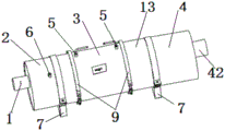
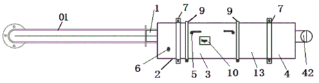
As shown in fig. 1-3 and 8, the present invention provides an engine exhaust purification device, which comprises an air inlet pipe 1, an oxidation catalyst 2, a particle catcher 3 and an exhaust chamber 4, which are connected in sequence, wherein the air inlet pipe 1 is connected with an exhaust pipe 01 of an engine, and the tail end of the exhaust chamber 4 is provided with an air outlet; and the inlet and the outlet of the particle catcher 3 are respectively provided with a differential pressure sensor 5, and the differential pressure sensors 5 are connected with a monitor in a cab. Wherein, can install the dispersion room of admitting air between intake pipe and oxidation catalyst converter, make things convenient for engine exhaust and oxidation catalyst converter abundant contact. The oxidation catalyst is DOC (diesel oxidation catalyst), is connected with an engine exhaust pipe through an air inlet pipe, and converts carbon monoxide (CO) and Hydrocarbon (HC) in engine exhaust into harmless water (H) through oxidation reaction2O) and carbon dioxide (CO)2) The structure form of the device is basically the same as that of the three-way catalytic converter, only the catalyst coating is different, and the DOC only has oxidation capacity and does not have reduction capacity.
The utility model discloses the theory of operation that utilizes oxidation catalyst converter and particle catcher to purify engine exhaust is CO, HC and partial Particulate Matter (PM) in disposing diesel engine exhaust through DOC surface coating's noble metal catalyst, and the particle catcher (also known as CDPF) by surface coating catalyst intercepts PM again and regenerates it when regeneration temperature reaches. The main function of the catalyst in the system is to reduce the temperature required for reaction, so that the continuous passive regeneration of the particulates in the DPF can be realized by utilizing the exhaust temperature of the engine, which is generally 200-500 ℃.
DOC is the abbreviation of Diesel Oxidation Catalyst (Diesel Oxidation Catalyst), generally refers to a ceramic or metal carrier coated with a noble metal Catalyst, in a continuous passive regeneration system, DPF often needs to carry a Catalyst coating or couple with an upstream DOC, the coupled DOC oxidizes NO to NO2Reuse of highly oxidizing NO2The trapped particulates are oxidized at about 250 ℃, the particulates accumulated on the DPF filter body are oxidized while being filtered and deposited, and are oxidized and combusted while maintaining dynamic balance, and the DPF filter body continuously operates for a long time under low back pressure, thereby prolonging the regeneration period and reducing the number of active regeneration. The DOC has an effective working temperature range of 200-350 ℃, can oxidize SOF in particles to reduce particle emission, and can oxidize CO and HC in exhaust gas to release oxidation heat to heat the DPF.
The particle catcher is a Diesel Particulate trap, namely a CDPF (short for catalyst Diesel Particulate Filter), namely a wall-flow cordierite honeycomb ceramic carrier (DPF), the shape of the Filter element is similar to that of a honeycomb ceramic catalyst, but two adjacent pore passages are blocked, one is blocked at an air inlet, the other is blocked at an outlet, and exhaust gas flows into the Filter element from an empty bag and must flow out of the adjacent pore passages through the porous wall surface of the ceramic, so that PM in the exhaust gas is dischargedIs deposited on the wall surface of each inflow channel. A layer of precious metal catalyst is coated on the DPF, and under the combined action of the DOC of the front section, particles in the DPF are oxidized at a lower temperature to achieve continuous regeneration of the DPF. With an upstream DOC, the coupled DOC oxidising NO to NO2Reuse of highly oxidizing NO2The trapped particles are oxidized, so that the particles accumulated on the filter body undergo a violent oxidation reaction at about 250 ℃, the particles are oxidized and combusted while being filtered and deposited, dynamic balance is kept, and the filter body continuously operates for a long time under low back pressure, so that the regeneration period is prolonged, and the number of active regeneration times is reduced.
The reaction equation is as follows: [ C ]]+ 2NO2→CO2+ 2NO
The effective working temperature range of the DOC is 200-450 ℃, so that Particulate Matters (PM) in particles can be oxidized, the emission of the particles is reduced, CO and HC in exhaust gas can be oxidized, the oxidation heat is released to heat the DPF, and a certain heat source is provided for subsequent regeneration. The DPF is also coated with a noble metal catalyst to enable NO, which has been reduced to NO in the DPF2Is oxidized again to NO in DPF2Immediately react with the carbon particles again.
The reaction equation is: NO + Ddo O2→ NO2 [C]+ 2NO2→CO2 + 2NO
Under the combined action of DOC and CDPF catalysts, the particulates in DPF can be oxidized into CO continuously at lower temperature2The DPF is exhausted, which is a highly efficient continuous passive regeneration particulate trap device.
Oxidation of CO and HC in diesel exhaust to harmless H by a diesel oxidation catalyst2O and CO2While also oxidizing NO to NO2. NOx, the main exhaust emission of diesel engines, is basically composed of NO and NO2High temperature combustion in the cylinder, and more than about 90% of the flue gas discharged by combustion is NO. DOC oxidation of NO to NO2Is indeed the most critical factor of the system. Because the carbon particles generally need a high temperature of 550-600 ℃ in the air to be oxidized into CO2But NO2The particle can be oxidized at more than 200 ℃, so that the regeneration temperature of the whole system is greatly reduced.
As shown in fig. 3 and 5, the oxidation catalyst 2 and the particle trap 3 are each provided with a temperature sensor 6, and the temperature sensor 6 is connected to a monitor. The temperature sensor can be used for monitoring the temperatures in the oxidation catalyst and the particle catcher in real time, and the tail gas treatment condition can be known in time.
In a specific embodiment of the present invention, the air inlet pipe 1 is connected to the oxidation catalyst 2, the oxidation catalyst 2 is connected to the particle trap 3, and the particle trap 3 is connected to the exhaust chamber 4 through the connecting members. As shown in fig. 2, the connecting member between the particle trap 3 and the exhaust chamber 4 is a flange 8, and the connecting members between the air inlet pipe 1 and the oxidation catalyst 2 and between the oxidation catalyst 2 and the particle trap 3 are hoops 9. By adopting the structure, the whole sealing effect can be ensured by utilizing the self-lubricating, corrosion-resistant and heat-stable sealing performance of the graphite gasket.
In a specific embodiment of the present invention, as shown in fig. 4 and 5, the particle trap 3 includes a casing 31, a DPF liner 32 and a DPF column core 33, the DPF column core 33 is disposed in the DPF liner 32, the DPF liner 32 is disposed in the casing 31, and a data plate 10, a differential pressure sensor connector 5 for mounting the differential pressure sensor, and a temperature sensor connector 6 for mounting the temperature sensor are disposed on a side wall of the casing 31. One end of the differential pressure sensor joint 5 and one end of the temperature sensor joint 6 are connected with the shell 31, the other end of the differential pressure sensor joint is connected with the elbow 12 through the clamping sleeve 11, and a lead connected with the differential pressure sensor and the temperature sensor is communicated in the elbow 12. And the outer wall of the shell is provided with a pressure measuring hole 15 for installing a differential pressure sensor and a temperature measuring hole 14 for installing a temperature sensor. The diesel engine tail gas enters an air inlet duct, and because the tail end of the air inlet duct is blocked, the tail gas must enter an adjacent exhaust duct through a filtering wall surface of the air inlet duct and is discharged into the atmosphere from the exhaust duct, and particulate matters in the tail gas are filtered and intercepted by the filtering wall surface in the process; the filtering efficiency is not lower than 95%.
In a specific embodiment of the utility model, as shown in fig. 6 and 7, the exhaust chamber 4 includes a gas outlet cylinder 41 and an eccentric air outlet pipe 42, the one end that the gas outlet cylinder 41 is adjacent with the particle catcher 3 is equipped with retaining ring 43, the other end is equipped with end cover 44, the middle part of end cover 44 is equipped with the venthole 45 that link up with air outlet pipe 42, the skew end cover 44 centre of a circle setting of venthole 45. The air inlet pipe is connected with an exhaust pipe of the engine through a heat-preservation stainless steel pipe. By adopting the structure, the flow speed of the tail gas can be delayed, particulate matters in the tail gas can be filtered, deposited and oxidized and combusted in the DOC and the DPF, and the effect of purifying and treating the tail gas is ensured.
Further optimizing the technical scheme, as shown in fig. 1 and 2, a silencer 13 is arranged between the exhaust chamber 4 and the particle catcher 3, a steering elbow is arranged in the silencer 13, and two ends of the steering elbow are respectively connected with an outlet of the particle catcher 3 and an inlet of the exhaust chamber 4. The noise of tail gas can be reduced by means of the silencer, and the surrounding environment can be purified.
In a specific embodiment of the present invention, as shown in fig. 9, the monitor includes a processor, a display screen and an alarm, and the differential pressure sensor, the temperature sensor, the display screen and the alarm are all connected to the processor. Can install display screen, alarm and treater in the driver's cabin, make things convenient for navigating mate real time monitoring tail gas treatment operating mode, it is timely right the utility model discloses maintain.
Further optimize above-mentioned technical scheme, watch-dog and mobile terminal wireless connection. The mobile terminal can select a computer or a mobile phone, so that the running state of the vehicle and the working state of the engine tail gas purification device can be conveniently displayed in real time, and the maintenance time is prompted. With information connection to computer or cell-phone on, the running state of real-time display vehicle the utility model discloses operating condition, suggestion the utility model discloses a maintenance time.
As shown in fig. 1 and 8, the engine exhaust gas purification device is connected with the outer wall of the engine through a bracket 7. The utility model discloses install in original silencer position to do not influence whole car performance and outward appearance.
To sum up, the main function of the present invention is to remove particulate matter, unburned Hydrocarbons (HC), carbon monoxide (CO) in the engine exhaust, and simultaneously to carry the relevant catalyst and to eliminate noise. Has the following advantages:
(1) purify tail gas, ensure that tail gas emission environmental protection is up to standard, purify the surrounding environment, be favorable to protecting staff's healthy.
(2) The staff passes through the display screen at the driver's cabin and can on-line monitoring, on information connection to computer or cell-phone, can show the running state of vehicle in real time and reach the utility model discloses an operating condition, its maintenance time of suggestion.
(3) The maintenance is simple and convenient, and the cleaning device can be detached for maintenance and cleaning once in a year.
(4) The utility model discloses install in original silencer position, do not influence whole car performance and outward appearance.
(5) Adopt the utility model discloses can reach the range estimation and do not have black cigarette, tasteless. The smoke value, hydrocarbon and carbon monoxide can reach the environmental protection standard.
The principles and embodiments of the present invention have been explained herein using specific examples, and the above descriptions of the embodiments are only used to help understand the method and its core ideas of the present invention. It should be noted that, for those skilled in the art, without departing from the principle of the present invention, the present invention can be further modified and modified, and such modifications and modifications also fall within the protection scope of the appended claims.
Claims (10)
1. An engine exhaust gas purification device which characterized in that: the device comprises an air inlet pipe, an oxidation catalyst, a particle catcher and an exhaust chamber which are connected in sequence, wherein the air inlet pipe is connected with an exhaust pipe of an engine, and the tail end of the exhaust chamber is provided with an air outlet; and the inlet and the outlet of the particle catcher are respectively provided with a differential pressure sensor, and the differential pressure sensors are connected with a monitor in a cab.
2. The engine exhaust gas purification device according to claim 1, characterized in that: the oxidation catalyst and the particle catcher are both provided with temperature sensors, and the temperature sensors are connected with a monitor.
3. The engine exhaust gas purification device according to claim 2, characterized in that: graphite gaskets are arranged between the air inlet pipe and the oxidation catalyst, between the oxidation catalyst and the particle catcher, and between the particle catcher and the exhaust chamber, and are connected through connecting pieces.
4. The engine exhaust gas purification device according to claim 3, characterized in that: the connecting pieces between the particle catcher and the exhaust chamber are flanging flanges, and the connecting pieces between the air inlet pipe and the oxidation catalyst and between the oxidation catalyst and the particle catcher are hoops.
5. The engine exhaust gas purification device according to claim 2, characterized in that: the particle catcher comprises a shell, a DPF lining and a DPF column core, wherein the DPF column core is arranged in the DPF lining, the DPF lining is arranged in the shell, and a nameplate and a sensor joint for mounting a differential pressure sensor and a temperature sensor are arranged on the side wall of the shell.
6. The engine exhaust gas purification device according to claim 1, characterized in that: the exhaust chamber comprises an air outlet cylinder and an eccentric air outlet pipe, a check ring is arranged at one end of the air outlet cylinder adjacent to the particle catcher, an end cover is arranged at the other end of the air outlet cylinder, an air outlet hole communicated with the air outlet pipe is formed in the middle of the end cover, and the air outlet hole is arranged in a mode of deviating from the circle center of the end cover.
7. The engine exhaust gas purification device according to claim 1, characterized in that: and a silencer is arranged between the exhaust chamber and the particle catcher, a steering elbow is arranged in the silencer, and two ends of the steering elbow are respectively connected with the outlet of the particle catcher and the inlet of the exhaust chamber.
8. The engine exhaust gas purification device according to claim 2, characterized in that: the monitor comprises a processor, a display screen and an alarm, and the differential pressure sensor, the temperature sensor, the display screen and the alarm are all connected with the processor.
9. The engine exhaust gas purification device according to claim 8, characterized in that: the monitor is in wireless connection with the mobile terminal.
10. The engine exhaust gas purification device according to any one of claims 1 to 8, characterized in that: the engine tail gas purification device is connected with the outer wall of the engine through a support.
Priority Applications (1)
| Application Number | Priority Date | Filing Date | Title |
|---|---|---|---|
| CN202020690546.5U CN212106016U (en) | 2020-04-29 | 2020-04-29 | Engine tail gas purification device |
Applications Claiming Priority (1)
| Application Number | Priority Date | Filing Date | Title |
|---|---|---|---|
| CN202020690546.5U CN212106016U (en) | 2020-04-29 | 2020-04-29 | Engine tail gas purification device |
Publications (1)
| Publication Number | Publication Date |
|---|---|
| CN212106016U true CN212106016U (en) | 2020-12-08 |
Family
ID=73618401
Family Applications (1)
| Application Number | Title | Priority Date | Filing Date |
|---|---|---|---|
| CN202020690546.5U Active CN212106016U (en) | 2020-04-29 | 2020-04-29 | Engine tail gas purification device |
Country Status (1)
| Country | Link |
|---|---|
| CN (1) | CN212106016U (en) |
Cited By (2)
| Publication number | Priority date | Publication date | Assignee | Title |
|---|---|---|---|---|
| CN114964824A (en) * | 2022-08-01 | 2022-08-30 | 北京复兰环保科技有限公司 | Vehicle aftertreatment unit testing method, device and system |
| WO2023098180A1 (en) * | 2021-11-30 | 2023-06-08 | 中船动力研究院有限公司 | Pretreatment system for engine black carbon emission test |
-
2020
- 2020-04-29 CN CN202020690546.5U patent/CN212106016U/en active Active
Cited By (3)
| Publication number | Priority date | Publication date | Assignee | Title |
|---|---|---|---|---|
| WO2023098180A1 (en) * | 2021-11-30 | 2023-06-08 | 中船动力研究院有限公司 | Pretreatment system for engine black carbon emission test |
| CN114964824A (en) * | 2022-08-01 | 2022-08-30 | 北京复兰环保科技有限公司 | Vehicle aftertreatment unit testing method, device and system |
| CN114964824B (en) * | 2022-08-01 | 2022-11-15 | 北京复兰环保科技有限公司 | Vehicle aftertreatment unit testing method, device and system |
Similar Documents
| Publication | Publication Date | Title |
|---|---|---|
| US7862640B2 (en) | Low temperature diesel particulate matter reduction system | |
| WO2011132918A2 (en) | Device for discharging exhaust gas from diesel engine, having ammonolysis module | |
| CN105402007A (en) | Box type post processing assembly for diesel vehicle | |
| RU2007131191A (en) | EXHAUST GAS TREATMENT SYSTEM | |
| CN212106016U (en) | Engine tail gas purification device | |
| CN210105952U (en) | Tail gas purification device for railway engineering machinery engine | |
| KR20140062899A (en) | Exhaust gas purification system of vehicle | |
| CN207974875U (en) | A kind of exhaust gas from diesel vehicle catalytic purification converter | |
| KR101011760B1 (en) | Novel SCR catalysts and after-treatment devices for diesel engine exhaust gas | |
| EP3864260B1 (en) | An exhaust aftertreatment unit for an exhaust system of an internal combustion engine | |
| WO2021097655A1 (en) | Intelligent diesel vehicle exhaust gas treatment system | |
| CN204663633U (en) | A kind of diesel engine high-performance exhaust gas cleaner | |
| CN210264859U (en) | Purifier is handled to generating set black cigarette | |
| CN111156068B (en) | Engine aftertreatment system and vehicle | |
| JP2012092746A (en) | Exhaust emission control device | |
| CN215521021U (en) | Diesel engine tail gas purification device | |
| CN214118297U (en) | Diesel engine tail gas purification device | |
| CN213270016U (en) | Diesel engine tail gas purification device | |
| CN211692608U (en) | Engine aftertreatment system and vehicle | |
| CN215057688U (en) | Tail gas aftertreatment assembly device of harvester | |
| CN214007286U (en) | Automobile double-exhaust system | |
| CN213063711U (en) | Automobile purification silencer | |
| CN108798837A (en) | A kind of device improving automobile engine using new energy resources effects of energy saving and emission reduction | |
| CN213980916U (en) | Automobile exhaust treatment device | |
| CN216446996U (en) | New material automobile exhaust purifier |
Legal Events
| Date | Code | Title | Description |
|---|---|---|---|
| GR01 | Patent grant | ||
| GR01 | Patent grant |