CN212094997U - ARM (advanced RISC machine) deflection integral welding tool for power tower - Google Patents
ARM (advanced RISC machine) deflection integral welding tool for power tower Download PDFInfo
- Publication number
- CN212094997U CN212094997U CN201922323129.7U CN201922323129U CN212094997U CN 212094997 U CN212094997 U CN 212094997U CN 201922323129 U CN201922323129 U CN 201922323129U CN 212094997 U CN212094997 U CN 212094997U
- Authority
- CN
- China
- Prior art keywords
- rod
- fixed
- arm
- positioning
- welding
- Prior art date
- Legal status (The legal status is an assumption and is not a legal conclusion. Google has not performed a legal analysis and makes no representation as to the accuracy of the status listed.)
- Active
Links
Images


Abstract
The utility model relates to a welding frock field, concretely relates to electric power tower ARM whole welding frock that shifts. Including the support body, ARM fishbone welded frame is located the support body, and the support body both sides are fixed with a plurality of stabilising arrangement that are used for stabilizing ARM fishbone welded frame, and the head end and the tail end middle part of support body all are fixed with the fixed plate, have all seted up the centre bore on the fixed plate, and the centre bore on support body head end and the tail end fixed plate is concentric, and all the hinge is connected with the location support on the fixed plate. The utility model discloses, simple structure, convenient operation, the angle that can overturn of frock can alleviate the labour, improve welding efficiency and welding quality, through setting up stabilising arrangement, has reduced welding deformation, has reduced the rework rate, conveniently transports ARM fishbone weld holder.
Description
Technical Field
The utility model relates to a welding frock field, concretely relates to electric power tower ARM whole welding frock that shifts.
Background
In the process of manufacturing the Danish power tower ARM, the welding difficulty is large, the deformation is large, the welding quality requirement is high, the welding mode in the industry at present is manual welding, the welding difficulty is large, and the problems of high labor intensity of workers, limited operation time, low welding efficiency, low welding quality and the like are caused. The electric power tower ARM is directly arranged on the ground to be spliced and welded, a welder can only squat or bend to weld, the position of the welder is required to be adjusted after a certain distance is welded, the welder needs to pause operation and enter a rest area to rest after welding for a certain time, weld forming and ARM deformation conditions are checked after welding, rework is performed on places which are not in place to be welded, and places with large ARM deformation are corrected. The existing working mode has the following defects: (1) the labor intensity of welders is high, continuous operation cannot be realized, and the welding efficiency is low; (2) the ARM is placed on the ground, a welder can only squat or bend to weld and cannot continuously weld, the welding efficiency is low, and the welding quality is poor; (3) the direct manual welding has large welding amount and large deformation; (4) the welding groove is a natural groove, and the welding seam is not well formed; (5) the direct manual welding results in low welding quality, large deformation and high rework rate.
Therefore, aiming at the series of problems, a set of deflection integral welding tool is designed, the tool can be turned over, the labor force is reduced, and the welding efficiency and the welding quality are improved; the pressure plate is added to the welding seam, and welding deformation is reduced.
SUMMERY OF THE UTILITY MODEL
The utility model aims to solve the technical problem that one kind can reduce intensity of labour, improves welding efficiency, and the welding seam shaping is good, and welding quality can show the improvement, can reduce welding deformation, reduces the electric power tower ARM whole welding frock that shifts of rework rate.
In order to realize the purpose, the utility model provides a technical scheme is:
an ARM deflection integral welding tool for a power tower comprises a frame body, an ARM fishbone welding frame is positioned on the frame body, a plurality of stabilizing devices for stabilizing the ARM fishbone welding frame are fixed on two sides of the frame body,
the stabilizing device comprises a vertical screw rod and a pressure rod, wherein the pressure rod is provided with a long groove along the length direction, the screw rod penetrates through the long groove of the pressure rod, the screw rod above the pressure rod is in threaded connection with a nut for locking the pressure rod, the middle parts of the head end and the tail end of the frame body are respectively fixed with a fixed plate, the fixed plates are respectively provided with a central hole, the central holes on the head end and the tail end of the frame body are concentric, and the fixed plates are respectively hinged with a positioning,
the positioning support comprises a bottom plate, a vertical plate vertical to the bottom plate is fixed at the upper end of the bottom plate, a through hole is arranged on the vertical plate, a connecting bolt penetrates through the through hole and then is in threaded connection with a central hole on a fixed plate, two positioning plates are fixed at the head end and the tail end of the frame body and are symmetrically arranged according to the central hole, three threaded holes are arranged on the positioning plates along the length direction of the positioning plates, two groups of positioning holes are symmetrically arranged on the vertical plate,
each group of positioning holes comprises a first opening formed by three straight lines and a second opening formed by two straight lines, the center hole distances of the first opening, the second opening and the threaded holes in the positioning plate are equal, the rotation track of the central line of the threaded holes on the positioning plate around the axis of the central hole passes through the central line of the first opening on one side of the positioning plate, and the rotation track of the threaded holes in the middle and below of the positioning plate around the axis of the central hole passes through the central line of the second opening on one side of the positioning plate.
Specifically, the frame body comprises a first rod, a third supporting rod parallel to the first rod is arranged on one side of the first rod, the first rod is fixedly connected with the third supporting rod through a first connecting rod, the first connecting rod is perpendicular to the first rod, a first supporting rod perpendicular to the first connecting rod is fixed on the first connecting rod between the first rod and the third supporting rod, an intermediate rod parallel to the third supporting rod is arranged on one side of the third supporting rod, the intermediate rod is fixedly connected with the third supporting rod through a second connecting rod, the second connecting rod is perpendicular to the third supporting rod, two symmetrically-arranged supporting rods are fixed at two ends of one side of the intermediate rod, one ends of the two supporting rods, far away from the intermediate rod, are mutually far away, one ends of the two supporting rods, far away from the intermediate rod, are fixedly connected through a tail rod, the two supporting rods on one side of the tail rod are fixedly connected, a plurality of fixing rods are uniformly distributed and fixed on the end surfaces, opposite to each other, along the length direction of, the upper ends of the fixed rods are all fixed with stabilizing devices.
Specifically, lifting lugs are fixed at the two ends of the first rod and the two ends of the tail rod.
Specifically, the first rod, the first connecting rod, the second connecting rod, the intermediate rod, the first supporting rod, the second supporting rod and the tail rod are all H-shaped steel.
Specifically, the included angle between the center connecting line of the first opening and the center connecting line of the second opening in the same group is 120 degrees, and the included angle between the center connecting line of the first opening and the center connecting line of the threaded hole in the positioning plate on one side of the first opening is 30 degrees.
Compared with the prior art, the beneficial effects of the utility model are that:
the utility model discloses, simple structure, convenient operation, the angle that can overturn of frock can alleviate the labour, improve welding efficiency and welding quality, through setting up stabilising arrangement, has reduced welding deformation, has reduced the rework rate, conveniently transports ARM fishbone weld holder.
Drawings
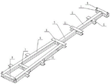
Fig. 1 is a schematic structural view of the present invention in use.
Fig. 2 is a schematic structural diagram of the connection of the frame body and the ARM fishbone welding frame.
Fig. 3 is a schematic structural diagram of the vertical plate.
Fig. 4 is a plan view of the shelf body.
Fig. 5 is an isometric view of a frame.
Detailed Description
As shown in fig. 1-5, an ARM welding frame 17 of a power tower is located on a frame body, and a plurality of stabilizing devices for stabilizing the ARM welding frame 17 are fixed on two sides of the frame body.
The stabilizing device comprises a vertical screw 12 and a pressing rod 13, wherein a long groove 14 is formed in the pressing rod 13 along the length direction of the pressing rod, the screw 12 penetrates through the long groove 14 of the pressing rod 13, a nut for locking the pressing rod 13 is connected to the screw 12 above the pressing rod 12 in a threaded mode, fixing plates 20 are fixed to the middle portions of the head end and the tail end of the frame body, central holes 21 are formed in the fixing plates 20, the central holes 21 in the head end and the tail end of the frame body are concentric, and positioning supports are hinged to the fixing plates 20.
The positioning support comprises a bottom plate 19, a vertical plate 18 perpendicular to the bottom plate 19 is fixed at the upper end of the bottom plate 19, a through hole 25 is formed in the vertical plate 18, a connecting bolt 22 penetrates through the through hole 25 and then is in threaded connection with a central hole 21 in a fixing plate 20, two positioning plates 15 are fixed at the head end and the tail end of the frame body, the two positioning plates 15 are symmetrically arranged according to the central hole 21, three threaded holes 16 are formed in the positioning plates 15 along the length direction of the positioning plates, and two groups of positioning holes are symmetrically formed.
Each group of positioning holes comprises a first opening 23 formed by three straight lines and a second opening 24 formed by two straight lines, the distances among the centers of the first opening 23, the second opening 24 and the threaded holes 16 on the positioning plate 15 are equal, the included angle between the center connecting lines of the first opening 23 and the second opening 24 in the same group is 120 degrees, the included angle between the center connecting line of the first opening 23 and the center connecting line of the threaded holes on the positioning plate 15 on one side is 30 degrees, the rotation track of the center line of the threaded holes 16 on the positioning plate 15 around the axis of the central hole 21 passes through the center line of the first opening 23 on one side, and the rotation track of the threaded holes 16 in the middle and below on the positioning plate 15 around the axis of the central hole 21 passes through the center line of the.
The frame body comprises a first rod 1, a third supporting rod 11 parallel to the first rod is arranged on one side of the first rod 1, the first rod 1 and the third supporting rod 11 are fixedly connected through a first connecting rod 2, the first connecting rod 2 is perpendicular to the first rod 1, a first supporting rod 5 perpendicular to the first connecting rod 2 is fixed on the first connecting rod 2 between the first rod 1 and the third supporting rod 11, an intermediate rod 4 parallel to the third supporting rod is arranged on one side of the third supporting rod 11, the intermediate rod 4 and the third supporting rod 11 are fixedly connected through a second connecting rod 3, the second connecting rod 3 is perpendicular to the third supporting rod 11, two symmetrically-arranged supporting rods 6 are fixed at two ends of one side of the intermediate rod 4, one ends of the two supporting rods 6 far away from the intermediate rod 4 are mutually far away, one ends of the two supporting rods 6 far away from the intermediate rod 4 are fixedly connected through a tail rod 8, the two supporting rods 6 on one side of the tail rod 8 are fixedly connected through a second supporting rod 7, a plurality of fixing rods 10 are uniformly, stabilizing devices are fixed at two ends of the first supporting rod 5, the third supporting rod 11 and the middle rod 4, stabilizing devices are fixed at the upper ends of the fixing rods 10, and lifting lugs 9 are fixed at two ends of the head rod 1 and two ends of the tail rod 8.
The first rod 1, the first connecting rod 2, the second connecting rod 3, the middle rod 4, the first supporting rod 5, the supporting rod 6, the second supporting rod 7 and the tail rod 8 are all H-shaped steel.
When the utility model is used, the bottom plate 19 is fixed on the welding platform, the ARM fishbone welding frame 17 is assembled and formed by spot welding in advance, then the ARM fishbone welding frame is placed on the frame body, the nut on the screw rod 12 is screwed to ensure that the pressure rod 13 is tightly propped against the ARM fishbone welding frame 17 on the frame body, the frame body can improve the height of the ARM fishbone welding frame 17, the welding is convenient, when the welding is needed, the frame body is rotated for 30 degrees around the connecting bolt 22, at the moment, three threaded holes 16 on one positioning plate 15 at one end of the frame body are respectively concentric with three first open holes 23 on the vertical plate 18 at one side of the frame body, the threaded holes 16 at the middle part and the lower end of the other positioning plate 15 are concentric with two second open holes 24 on the vertical plate 18 at one side of the other positioning plate, the fixing bolt 26 penetrates through the first open hole 23 and the second open hole 24, the support body is stabilized this moment, and ARM fishbone welded frame 17's welding seam is towards the workman, conveniently welds ARM fishbone welded frame 17's welding seam. The frame body is fixed with the lug, conveniently removes ARM fishbone weld holder 17.
The above description is only exemplary of the present invention and should not be taken as limiting the scope of the present invention, as any modifications, equivalents, improvements and the like made within the spirit and principles of the present invention are intended to be included within the scope of the present invention.
Claims (5)
1. An ARM (advanced RISC machine) deflection integral welding tool for a power tower comprises a frame body, wherein an ARM fishbone welding frame (17) is positioned on the frame body, and is characterized in that a plurality of stabilizing devices for stabilizing the ARM fishbone welding frame (17) are fixed on two sides of the frame body,
the stabilizing device comprises a vertical screw rod (12) and a pressing rod (13), wherein an elongated slot (14) is formed in the pressing rod (13) along the length direction of the pressing rod, the screw rod (12) penetrates through the elongated slot (14) of the pressing rod (13), a nut for locking the pressing rod (13) is in threaded connection with the screw rod (12) above the pressing rod (13), fixing plates (20) are fixed to the middle portions of the head end and the tail end of the frame body, central holes (21) are formed in the fixing plates (20), the central holes (21) in the head end and the tail end of the frame body are concentric, and positioning supports are hinged to the fixing plates (20),
the positioning support comprises a bottom plate (19), a vertical plate (18) vertical to the bottom plate (19) is fixed at the upper end of the bottom plate (19), a through hole (25) is formed in the vertical plate (18), a connecting bolt (22) penetrates through the through hole (25) and then is in threaded connection with a central hole (21) in a fixing plate (20), two positioning plates (15) are fixed at the head end and the tail end of the frame body, the two positioning plates (15) are symmetrically arranged according to the central hole (21), three threaded holes (16) are formed in the positioning plates (15) along the length direction of the positioning plates, two groups of positioning holes are symmetrically formed in,
each group of positioning holes comprises a first opening (23) formed by three straight lines and a second opening (24) formed by two straight lines, the center hole distances of the first opening (23), the second opening (24) and the threaded holes (16) in the positioning plate (15) are equal, the rotation track of the center line of the threaded holes (16) in the positioning plate (15) around the axis of the center hole (21) passes through the center line of the first opening (23) on one side of the positioning plate, and the rotation track of the threaded holes (16) in the middle and below in the positioning plate (15) around the axis of the center hole (21) passes through the center line of the second opening (24) on one side of the positioning plate.
2. The electric power tower ARM displacement integral welding tool according to claim 1, wherein the frame body comprises a first rod (1), a third support rod (11) parallel to the first rod is arranged on one side of the first rod (1), the first rod (1) and the third support rod (11) are fixedly connected through a first connecting rod (2), the first connecting rod (2) is perpendicular to the first rod (1), a first support rod (5) perpendicular to the first connecting rod is fixed on the first connecting rod (2) between the first rod (1) and the third support rod (11), an intermediate rod (4) parallel to the third support rod is arranged on one side of the third support rod (11), the intermediate rod (4) and the third support rod (11) are fixedly connected through a second connecting rod (3), the second connecting rod (3) is perpendicular to the third support rod (11), two symmetrically arranged support rods (6) are fixed at two ends of one side of the intermediate rod (4), and ends, far away from the intermediate rod (4), of the two support rods (6) are far away from each other, the one end that intermediate lever (4) were kept away from in two vaulting poles (6) passes through tail-bar (8) fixed connection, and two vaulting poles (6) of tail-bar (8) one side are fixed with a plurality of dead levers (10) along its length direction equipartition on the terminal surface that two vaulting poles (6) carried on the back mutually, and the both ends of first branch (5), third branch (11) and intermediate lever (4) all are fixed with stabilising arrangement, and dead lever (10) upper end all is fixed with stabilising arrangement.
3. The electric power tower ARM integral welding frock that shifts of claim 2, characterized in that, lug (9) are all fixed with at first pole (1) both ends and tail-stock (8) both ends.
4. The electric power tower ARM integral welding frock that shifts of claim 2, characterized in that, first pole (1), first connecting rod (2), second connecting rod (3), intermediate lever (4), first branch (5), vaulting pole (6), second branch (7), tail-stock (8) are H shaped steel.
5. The electric tower ARM integral welding tool that shifts of claim 1, characterized by, that lies in the contained angle of the line of the center of a first trompil (23) and second trompil (24) of a same group 120 degrees, the contained angle of the line of the center of first trompil (23) and the line of the center of the screw hole on its one side locating plate (15) is 30 degrees.
Priority Applications (1)
| Application Number | Priority Date | Filing Date | Title |
|---|---|---|---|
| CN201922323129.7U CN212094997U (en) | 2019-12-23 | 2019-12-23 | ARM (advanced RISC machine) deflection integral welding tool for power tower |
Applications Claiming Priority (1)
| Application Number | Priority Date | Filing Date | Title |
|---|---|---|---|
| CN201922323129.7U CN212094997U (en) | 2019-12-23 | 2019-12-23 | ARM (advanced RISC machine) deflection integral welding tool for power tower |
Publications (1)
| Publication Number | Publication Date |
|---|---|
| CN212094997U true CN212094997U (en) | 2020-12-08 |
Family
ID=73624675
Family Applications (1)
| Application Number | Title | Priority Date | Filing Date |
|---|---|---|---|
| CN201922323129.7U Active CN212094997U (en) | 2019-12-23 | 2019-12-23 | ARM (advanced RISC machine) deflection integral welding tool for power tower |
Country Status (1)
| Country | Link |
|---|---|
| CN (1) | CN212094997U (en) |
-
2019
- 2019-12-23 CN CN201922323129.7U patent/CN212094997U/en active Active
Similar Documents
| Publication | Publication Date | Title |
|---|---|---|
| CN201516541U (en) | Clamping device for laser welding of battery shell | |
| CN202780248U (en) | Laser welding positioning fixture | |
| CN111906478A (en) | Construction method for manual welding wire of steel structure | |
| CN212094997U (en) | ARM (advanced RISC machine) deflection integral welding tool for power tower | |
| CN110893529A (en) | ARM (advanced RISC machine) deflection integral welding tool for power tower | |
| CN106141522A (en) | A kind of steel plate fillet welding automatic soldering device | |
| CN214054222U (en) | Adjustable welding tool rack for steel pipe pole cross arm | |
| CN105328369A (en) | Welding device for rib of forklift portal-frame | |
| CN214602729U (en) | Quick assembly welding device for stiffening ring of large-sized pressure steel pipe | |
| CN212761853U (en) | Auxiliary support tool for manual wire welding of steel structure | |
| CN210232048U (en) | Welding working frame | |
| CN211939667U (en) | Right-angle welding fixture for civil air defense door | |
| CN107486618A (en) | Spot welding device | |
| CN209394238U (en) | A kind of ingot beam welding positioning tool and welder | |
| CN204565404U (en) | A kind of multiple degrees of freedom multi-angle rocker arm spot welder | |
| CN211991485U (en) | Device for welding inclined support piece | |
| CN107498139B (en) | Multi-angle welding device | |
| CN218904142U (en) | Intelligent robot flange assembly welding special plane | |
| CN218311377U (en) | Semi-automatic gas shielded welding frock of I-steel | |
| CN218926752U (en) | A cross gusset welding position frock for I-steel beam | |
| CN212350846U (en) | Double-gun automatic welding for container reinforced angle steel | |
| CN207914851U (en) | A kind of straight seam welding special plane of forklift door frame weldment | |
| CN216656693U (en) | Automatic submerged arc welding tool | |
| CN217316732U (en) | Longitudinal joint welding set in steel-pipe pile | |
| CN214641469U (en) | Single-station circular welding machine |
Legal Events
| Date | Code | Title | Description |
|---|---|---|---|
| GR01 | Patent grant | ||
| GR01 | Patent grant |