CN212078127U - Integrated water tank - Google Patents
Integrated water tank Download PDFInfo
- Publication number
- CN212078127U CN212078127U CN202020655605.5U CN202020655605U CN212078127U CN 212078127 U CN212078127 U CN 212078127U CN 202020655605 U CN202020655605 U CN 202020655605U CN 212078127 U CN212078127 U CN 212078127U
- Authority
- CN
- China
- Prior art keywords
- tableware
- box
- water tank
- rack
- tank body
- Prior art date
- Legal status (The legal status is an assumption and is not a legal conclusion. Google has not performed a legal analysis and makes no representation as to the accuracy of the status listed.)
- Active
Links
Images


Abstract
The utility model provides an integrated sink relates to kitchen supplies technical field. The integrated water tank comprises a water tank body and a disinfection assembly, wherein the disinfection assembly comprises a containing box, a disinfection part arranged in the containing box and a tableware rack contained in the containing box, the tableware rack is used for placing tableware, and one side of the tableware rack, which faces the water tank body, is provided with an opening suitable for taking and placing the tableware; the disinfection component is used for disinfecting tableware on the tableware rack; the containing box is fixedly arranged on the side part of the water tank body, and the box opening of the containing box is consistent with the notch of the water tank body; the water tank body or the containing box is provided with a driving component, and the driving end of the driving component is connected with the tableware rack and used for driving the tableware rack to ascend and extend out of the containing box or descend and contain in the containing box. The integrated water tank is high in sanitation and use convenience.
Description
Technical Field
The utility model belongs to the technical field of the kitchen supplies technique and specifically relates to an integrated basin is related to.
Background
The water tank is a necessary kitchen ware for cleaning tableware, food materials, fruits and the like in a household kitchen, the disinfection cabinet is a functional cabinet body for disinfecting the tableware in the household kitchen, and the disinfection cabinet mainly comprises an embedded disinfection cabinet and a table disinfection cabinet, wherein the embedded disinfection cabinet is generally embedded in a floor cabinet below the water tank, and the table disinfection cabinet is placed on a table board of the cabinet or other places; after a user cleans tableware in a water tank, the tableware needs to be placed in a disinfection cabinet for disinfection treatment, and in the placing process, residual water on the tableware can drip downwards to wet the ground or the table top of the cabinet, so that the kitchen cleanliness is affected and bacteria are easy to breed; in addition, when embedded sterilizer used, the user still needed to bow just can put into the sterilizer tableware, and this operation is poor to the user especially to old person's degree of use convenience.
That is, when the conventional sink is used together with the disinfection cabinet, the sanitation and convenience of use are poor.
SUMMERY OF THE UTILITY MODEL
An object of the utility model is to provide an integrated basin to when alleviating the basin that exists among the prior art and use together with the sterilizer, sanitary nature and the convenient all relatively poor technical problem of degree of use.
The embodiment provides an integrated sink, which comprises a sink body and a disinfection assembly, wherein the disinfection assembly comprises an accommodating box, a disinfection part arranged in the accommodating box and a tableware rack accommodated in the accommodating box, the tableware rack is used for placing tableware, and an opening suitable for taking and placing the tableware is arranged on one side of the tableware rack facing the sink body; the disinfection component is used for disinfecting tableware on the tableware rack;
the accommodating box is fixedly arranged on the side part of the water tank body, and a box opening of the accommodating box is consistent with the notch of the water tank body; the water tank body or the containing box is provided with a driving assembly, and the driving end of the driving assembly is connected with the tableware rack and used for driving the tableware rack to ascend and extend out of the containing box or descend and contain in the containing box.
In an alternative embodiment, the dish rack comprises a supporting frame and a dish basket installed in the supporting frame, and when the dish rack is accommodated in the accommodating box, the top surface of the top plate of the supporting frame is matched with the box opening of the accommodating box.
In an optional embodiment, the driving assembly includes a driving motor installed in the accommodating box, a screw rod pivoted to a bottom plate of the accommodating box, and a sliding seat in threaded connection with the screw rod, the sliding seat is fixedly connected to the dish rack, and a driving end of the driving motor is fixedly connected to a bottom end of the screw rod; the tableware rack is connected with the containing box in a sliding mode along the up-down direction.
In an alternative embodiment, the accommodating box is arranged at the rear side of the water tank body, and the water tank body and the accommodating box form an integral structure.
In an alternative embodiment, the sterilizing part includes an ultraviolet lamp mounted to a side wall of the receiving box near the sink body.
In an alternative embodiment, the ultraviolet lamp housing is provided with a first mesh enclosure.
In an optional embodiment, a drying component is further disposed in the accommodating box, and the drying component is used for drying the tableware on the tableware rack.
In an optional embodiment, the drying component includes a drying lamp, and the drying lamp is installed in the accommodating box and close to the side wall of the water tank body.
In an optional implementation manner, a circulating fan is installed outside the accommodating box, and an air inlet and an air outlet of the circulating fan are communicated with the inside of the accommodating box.
In an optional embodiment, the integrated water tank further comprises a processor, and the driving assembly, the disinfecting part, the drying part and the circulating fan are all connected with the processor; and a switch is arranged on the top surface of the water tank body or the top surface of the containing box and is connected with the processor.
The utility model discloses integrated basin's beneficial effect includes:
the utility model provides an integrated sink, including being used for holding the tableware and carrying out abluent basin body to it and being used for carrying out the disinfection subassembly of disinfection processing to the tableware, the disinfection subassembly is including the tableware frame that is used for placing the tableware, be used for forming the holding box of disinfection cavity jointly with the tableware frame, be used for carrying out the disinfection part of disinfection processing to the tableware in the disinfection cavity and be used for driving the tableware frame and stretch out the holding box outside or retract the drive assembly in the holding box.
Initially, the accommodating box is arranged on the side part of the water tank body, and the driving assembly drives the tableware rack to be accommodated in the accommodating box; when the user washs the tableware and need carry out disinfection treatment to the tableware in basin body department, can control drive assembly drive tableware rack upward movement and stretch out the box mouth of holding box, correspondingly also rise to the top of basin body, because tableware rack is provided with the uncovered that is suitable for getting to put the tableware towards one side of basin body, then the user can be directly put into the tableware rack with the tableware after basin body department washs through this uncovered, should place the in-process, the residual water on the tableware directly drips to the basin originally internal, can not drench ground or cupboard mesa, can also reduce the bacterial growing that water stain leads to, thereby improve kitchen cleaning nature and sanitary nature. In addition, the tableware rack can be lifted above the water tank, and in the arm operation range when the tableware rack is used by a user, the washed tableware can be placed in the tableware rack without stooping in the process of placing the tableware in the tableware rack, so that the convenience of combined use of the water tank and the disinfection cabinet is improved, and the labor capacity of the user is reduced.
After the tableware is placed, the driving assembly is controlled to drive the tableware rack to descend into the containing box, the space in the tableware rack is communicated with the space in the containing box, the space in the tableware rack and the space in the containing box form a disinfection chamber together, and the tableware is positioned in the disinfection chamber; and opening the disinfection part to disinfect the tableware in the disinfection chamber. After the disinfection treatment is finished, the drive assembly can be controlled to drive the tableware rack to ascend and extend out of the containing box, and the disinfected tableware can be taken out to be placed or used.
Drawings
In order to more clearly illustrate the embodiments of the present invention or the technical solutions in the prior art, the drawings used in the embodiments or the technical solutions in the prior art will be briefly described below, and it is obvious that the drawings in the following description are some embodiments of the present invention, and for those skilled in the art, other drawings can be obtained according to these drawings without creative efforts.
Fig. 1 is a schematic view of a tableware rack accommodated in a containing box in an integrated water tank according to an embodiment of the present invention;
fig. 2 is a schematic view of the integrated sink with the dish rack extending out of the storage box according to the embodiment of the present invention;
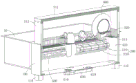
fig. 3 is a schematic cross-sectional view of the back of the integrated water tank of fig. 2.
Icon: 10-a sink body; 20-a disinfecting assembly; 100-a containing box; 110-a box opening; 200-a disinfecting component; 210-ultraviolet lamps; 220-a first mesh enclosure; 300-a tableware rack; 310-a support frame; 311-top plate; 312-side plate; 313-a lap-joint table; 320-a cutlery basket; 400-a drive assembly; 410-a drive motor; 420-a screw rod; 500-a drying component; 600-a circulating fan; 610-an air inlet; 620-air outlet; 700-a switch; 800-tableware.
Detailed Description
In order to make the objects, technical solutions and advantages of the embodiments of the present invention clearer, the embodiments of the present invention will be clearly and completely described below with reference to the accompanying drawings in the embodiments of the present invention, and it is obvious that the described embodiments are some, but not all, embodiments of the present invention. The components of embodiments of the present invention, as generally described and illustrated in the figures herein, may be arranged and designed in a wide variety of different configurations.
Thus, the following detailed description of the embodiments of the present invention, presented in the accompanying drawings, is not intended to limit the scope of the invention, as claimed, but is merely representative of selected embodiments of the invention. Based on the embodiments in the present invention, all other embodiments obtained by a person skilled in the art without creative efforts belong to the protection scope of the present invention.
It should be noted that: like reference numbers and letters refer to like items in the following figures, and thus, once an item is defined in one figure, it need not be further defined and explained in subsequent figures.
In the description of the present invention, it should be noted that the terms "upper", "lower", "vertical", "horizontal", "inner", "outer", and the like indicate the directions or positional relationships based on the directions or positional relationships shown in the drawings, or the directions or positional relationships that the products of the present invention are usually placed when in use, and are only for convenience of describing the present invention and simplifying the description, but do not indicate or imply that the device or element to which the term refers must have a specific direction, be constructed and operated in a specific direction, and thus, should not be construed as limiting the present invention.
Furthermore, the terms "horizontal", "vertical" and the like do not imply that the components are required to be absolutely horizontal or pendant, but rather may be slightly inclined. For example, "horizontal" merely means that the direction is more horizontal than "vertical" and does not mean that the structure must be perfectly horizontal, but may be slightly inclined.
In the description of the present invention, it should also be noted that, unless otherwise explicitly specified or limited, the terms "disposed," "mounted," "connected," and "connected" are to be construed broadly, e.g., as meaning either a fixed connection, a removable connection, or an integral connection; can be mechanically or electrically connected; they may be connected directly or indirectly through intervening media, or they may be interconnected between two elements. The specific meaning of the above terms in the present invention can be understood in specific cases to those skilled in the art.
Some embodiments of the present invention will be described in detail below with reference to the accompanying drawings. The embodiments described below and the features of the embodiments can be combined with each other without conflict.
The embodiment provides an integrated sink, as shown in fig. 1-3, including a sink body 10 and a disinfecting assembly 20, where the disinfecting assembly 20 includes a receiving box 100, a disinfecting part 200 installed in the receiving box 100, and a dish rack 300 received in the receiving box 100, the dish rack 300 is used for placing dishes, and one side of the dish rack 300 facing the sink body 10 is provided with an opening suitable for taking and placing the dishes, and the opening may be in a direct and unshielded opening form or an opening form with an openable and closable door; the sterilizing part 200 is used for sterilizing the dishes 800 on the dish rack 300; the accommodating box 100 is fixedly arranged on the side part of the water tank body 10, and a box opening 110 of the accommodating box 100 is consistent with the notch of the water tank body 10; the water tank body 10 or the receiving box 100 is provided with a driving assembly 400, and a driving end of the driving assembly 400 is connected to the dish rack 300 and is used for driving the dish rack 300 to ascend and extend out of the receiving box 100 or descend and be received in the receiving box 100.
The integrated sink provided by the embodiment comprises a sink body 10 for accommodating tableware 800 to clean the same and a sterilizing assembly 20 for sterilizing the tableware 800, wherein the sterilizing assembly 20 comprises a tableware rack 300 for placing the tableware 800, a containing box 100 for forming a sterilizing chamber together with the tableware rack 300, a sterilizing part 200 for sterilizing the tableware 800 in the sterilizing chamber, and a driving assembly 400 for driving the tableware rack 300 to extend out of the containing box 100 or retract into the containing box 100.
Initially, the receiving box 100 is disposed at a side portion of the sink body 10, and the driving assembly 400 drives the dish rack 300 to be received in the receiving box 100; when the user washes the tableware and needs to disinfect the tableware 800 at the sink body 10, the driving assembly 400 can be controlled to drive the tableware rack 300 to move upwards to stretch out the box opening 110 of the accommodating box 100, and correspondingly, the tableware rack 300 also rises to the upper side of the sink body 10, because the tableware rack 300 is arranged towards the opening in one side of the sink body 10, the user can directly place the tableware 800 washed at the sink body 10 into the tableware rack 300 through the opening, in the placing process, residual water on the tableware directly drips into the sink body 10, the ground or a cabinet table top cannot be wetted, bacterial breeding caused by water stains can be reduced, and therefore kitchen cleanliness and sanitation are improved. In addition, since the dish rack 300 can be lifted above the water tub, the washed dishes can be placed in the dish rack 300 without stooping in the process of placing the dishes 800 in the dish rack 300 by a user within the arm operating range when the dish rack 300 is set up by the user, thereby improving the convenience of the combined use of the water tub and the sterilizing cabinet and reducing the labor capacity of the user.
After the tableware 800 is placed, the driving assembly 400 is controlled to drive the tableware rack 300 to descend into the accommodating box 100, the space in the tableware rack 300 is communicated with the space in the accommodating box 100, the space in the tableware rack 300 and the space in the accommodating box 100 form a disinfection chamber together, and the tableware 800 is positioned in the disinfection chamber; the sterilizing part 200 is opened to sterilize the dishes in the sterilizing chamber. After the sterilization process is completed, the driving assembly 400 may be controlled to drive the dish rack 300 to ascend and extend out of the receiving box 100, and the sterilized dishes may be taken out for placing or using.
Specifically, when the sink body 10 is used, the position of the user facing the sink body 10 is taken as a reference, the accommodating box 100 may be disposed on the left side, the right side or the rear side of the sink body 10, and when the accommodating box 100 is located on the left side of the sink body 10, the right side of the dish rack 300 is disposed in an open manner; when the receiving box 100 is located at the right side of the sink body 10, the left side of the dish rack 300 is open; when the receiving box 100 is located at the rear side of the sink body 10, the front side of the dish rack 300 is open.
Preferably, the receiving box 100 can be disposed at the rear side of the water tank body 10, and the water tank body 10 and the receiving box 100 are formed into an integral structure, which can be an integral structure or welded into an integral structure. When the tableware rack 300 is used, the tableware rack 300 is positioned on the front side of a user, the user can clearly see the structure, the position and the like of the tableware rack 300, and the user can put tableware into the tableware rack 300 by extending arms forwards, so that the operation convenience is further improved. The water tank body 10 and the accommodating box 100 are integrally formed, so that on one hand, the connection firmness of the water tank body 10 and the accommodating box 100 can be improved, and the integration integrity of the water tank body 10 and the accommodating groove is improved; on the other hand, the gap between the containing box 100 and the sink body 10 is not left, so that the dripping of residual water of the tableware on the ground and the floor of the cabinet can be further reduced in the process of placing the tableware, and the use convenience and sanitation of the integrated sink can be correspondingly further improved. Specifically, the left and right sidewalls of the receiving box 100 may be identical to the left and right sidewalls of the sink body 10 to further improve the integrity of the integrated sink.
Alternatively, in this embodiment, the dish rack 300 may include a support frame 310 and a dish basket 320 installed in the support frame 310, and when the dish rack 300 is accommodated in the accommodating box 100, the top surface of the top plate 311 of the support frame 310 matches with the box opening 110 of the accommodating box 100. Here is a specific form of the dish rack 300, specifically, the supporting frame 310 may include a top plate 311 and two side plates 312 respectively connected to two ends of the top plate 311, three plates form a frame body with an open lower end (the lower ends of the two side plates 312 may also be connected to a bottom plate, and four plates form a closed frame body), a placing space is formed inside the frame body, the dish basket 320 may be approximately horizontally connected between the two side plates 312, and both sides of the supporting frame 310 are open, so that connectivity between the inside of the dish rack 300 and the inside of the accommodating box 100 can be effectively improved, and a disinfection effect of the disinfection component on the dishes 800 is ensured; the drive end of drive assembly 400 may be coupled to support frame 310 and may also be coupled to cutlery basket 320. When the driving assembly 400 drives the dish rack 300 to descend into the accommodating box 100, the top surface of the top plate 311 is at the same height as the box opening 110 of the accommodating box 100, and can approximately seal and seal the box opening 110, and the top surface of the sterilizing assembly 20 is approximately a horizontal table top, so that the occupation of the sterilizing assembly 20 on the space above the table top of the cabinet and the influence on the flatness of the table top of the kitchen are reduced.
Alternatively, as shown in fig. 3, two opposite sides of the supporting frame 310 may be provided with two engaging platforms 313, the cutlery basket 320 may be detachably engaged between the two engaging platforms 313, and after a period of use, the cutlery basket 320 may be detached for cleaning and then re-installed after cleaning, thereby further improving the convenience of use of the sterilizing assembly 20.
Alternatively, in this embodiment, as shown in fig. 3, the driving assembly 400 may include a driving motor 410 installed in the accommodating box 100, a screw rod 420 pivoted to a bottom plate of the accommodating box 100, and a sliding seat screwed to the screw rod 420, the sliding seat is fixedly connected to the dish rack 300, and a driving end of the driving motor 410 is fixedly connected to a bottom end of the screw rod 420; the dish rack 300 is slidably coupled to the receiving box 100 in the vertical direction. Here, it is a specific form of the driving assembly 400, when the driving assembly 400 is required to drive the dish rack 300 to move up and down, the driving motor 410 is controlled to rotate towards the first direction, the driving motor 410 correspondingly drives the screw rod 420 to rotate towards the first direction, the sliding seat is fixedly connected with the dish rack 300, the dish rack 300 is slidably connected to the accommodating box 100 along the up-down direction, and the sliding seat and the dish rack 300 move upwards relative to the accommodating box 100 under the combined action of the rotation driving of the screw rod 420 and the guiding and limiting of the accommodating box 100 to extend out of the accommodating box 100; when the set height is reached, the drive motor 410 is turned off. Similarly, the driving motor 410 is controlled to rotate in a second direction opposite to the first direction, the driving motor 410 correspondingly drives the screw rod 420 to rotate in the second direction, and the sliding seat and the dish rack 300 move downward relative to the receiving box 100 and are received in the receiving box 100. Preferably, the driving assemblies 400 can be two sets, and the two sets of driving assemblies 400 are respectively disposed on two sides of the length direction of the dish rack 300, and when the tableware rack is used, the two sets of driving assemblies 400 simultaneously drive two ends of the dish rack 300 synchronously, so that the dish rack 300 can move up and down stably, the use stability of the sterilizing assembly 20 is improved, and the stability of the dish rack 300 for bearing tableware is ensured.
In addition to the above form, the driving assembly 400 may also adopt a telescopic driving member such as a push rod motor, or may also adopt a rack and pinion mechanism, a link mechanism, or other mechanisms capable of driving the dish rack 300 up and down.
In this embodiment, as shown in fig. 3, the sterilizing part 200 may include an ultraviolet lamp 210, and the ultraviolet lamp 210 is installed on the sidewall of the accommodating box 100 close to the sink body 10. Here, in a specific form of the sterilizing part 200, after the dish rack 300 descends into the accommodating box 100, the ultraviolet lamp 210 is turned on, the ultraviolet lamp 210 releases ultraviolet rays into the sterilizing chamber, and the ultraviolet rays can kill bacteria, spores, viruses and the like on the dishes, thereby realizing the sterilizing treatment of the dishes; after a certain period of sterilization, the ultraviolet lamp 210 is turned off. In addition, the sterilizing part 200 may be in another form, such as an ozone generator, for performing ozone sterilization on the tableware; or a high temperature generating device for highly sterilizing the tableware.
Alternatively, as shown in fig. 3, a first mesh cover 220 may be disposed outside the ultraviolet lamp 210. The first mesh enclosure 220 does not shield the ultraviolet lamp 210 from releasing ultraviolet rays outwards, so as to ensure the disinfection treatment of the ultraviolet lamp 210 on tableware in the disinfection chamber; in addition, the first mesh enclosure 220 can protect the ultraviolet lamp 210, so as to reduce the collision damage of the parts such as the tableware rack 300 to the ultraviolet lamp 210 in the installation or use process, thereby effectively prolonging the service life of the ultraviolet lamp 210.
Optionally, in this embodiment, as shown in fig. 3, a drying component 500 may be further disposed in the accommodating box 100, and the drying component 500 is used for drying the dishes on the dish rack 300. After the tableware shelf 300 carrying the tableware to be sterilized enters the accommodating box 100, the drying part 500 can be opened to dry the tableware in the sterilizing chamber, so as to reduce the residual water on the tableware and correspondingly reduce the problems of bacterial breeding and the like caused by the residual water, thereby improving the functionality of the sterilizing assembly 20 and improving the sanitation of the tableware.
Specifically, in this embodiment, the drying part 500 may include a drying lamp, and the drying lamp is installed in the accommodating box 100 near the side wall of the sink body 10. Here, in a specific form of the drying part 500, the drying lamp can heat the air in the sterilization chamber into high-temperature gas, and the residual water on the surface of the tableware contacts with the high-temperature gas to absorb heat and evaporate into vapor to be separated from the tableware, thereby drying the tableware; specifically, a vent hole may be formed in the receiving box 100, so that water vapor can be emitted through the vent hole; in order to reduce or even avoid the leakage of ultraviolet rays, the sterilization chamber can be kept as a sealed chamber, after drying, the driving assembly 400 is controlled to drive the dish rack 300 to extend upwards out of the accommodating box 100, and water vapor in the dish rack 300 can escape through the opening of the dish rack 300.
In this embodiment, a second mesh enclosure may be disposed outside the drying lamp. The second screen panel can play the guard action to the stoving lamp on not influencing the outside radiating basis of stoving lamp to reduce installation or use, tableware frame 300 etc. damage the collision that the stoving lamp caused, thereby effectively prolong the life of stoving lamp.
In this embodiment, as shown in fig. 3, a circulating fan 600 may be further installed outside the accommodating box 100, and both the air inlet 610 and the air outlet 620 of the circulating fan 600 are communicated with the inside of the accommodating box 100. When the drying component 500 is used for drying tableware, the circulating fan 600 can be opened, the circulating fan 600 sucks the gas in the disinfection chamber through the gas inlet 610, and the gas is accelerated and then flows into the disinfection chamber through the gas outlet 620 at a high speed, so that the high-temperature gas in the disinfection chamber forms flowing circulation, the contact sufficiency of the tableware and the high-temperature air is improved, and the drying effect of the high-temperature air on the tableware is correspondingly improved.
In this embodiment, the integrated water tank may further include a processor, and the driving assembly 400, the sterilizing part 200, the drying part 500 and the circulating fan 600 are all connected to the processor; as shown in fig. 1-3, a switch 700 is disposed on the top surface of the sink body 10 or the top surface of the receiving box 100, and the switch 700 is connected to the disposer. A control program can be set in the processor, when the sterilizing assembly 20 needs to be used, the switch 700 is pressed, the processor receives the electric signal of the switch 700 for the first time, the electric signal is identified as an opening signal, the driving assembly 400 is correspondingly controlled to drive the tableware rack 300 to ascend to a set height, and a user can put washed tableware into the tableware rack 300; after the tableware is placed, the user can press the switch 700 again, the processor receives the electric signal of the switch 700 again and recognizes the electric signal as a starting signal, the driving assembly 400 is correspondingly controlled to drive the tableware rack 300 to descend to the initial position, the driving assembly 400 transmits the electric signal after driving is completed to the processor, the processor correspondingly starts the sterilizing part 200, the drying part 500 and the circulating fan 600, the sterilizing part 200 performs sterilizing treatment on the tableware, the drying part 500 performs drying treatment on the tableware, the circulating fan 600 assists the drying part 500 to promote airflow in the sterilizing chamber to flow, the three parts are automatically closed after running for a set time respectively, and the sterilizing assembly 20 completes sterilizing and drying treatment on the tableware. After the completion of the operation, the processor receives the completion signal, and controls the driving unit 400 to drive the dish rack 300 to ascend again, and after the user takes out the dishes on the dish rack 300 (the detection of the movement can be realized by providing the gravity sensor on the dish rack 300), the processor controls the driving unit 400 to drive the dish rack 300 to descend.
It should be noted that, in the present application, the connection relationship between the disposer and the sterilizing assembly 20, the switch 700, the drying unit 500, the circulating fan 600, etc. belongs to the improvement of the present application, and the setting of the program in the disposer according to the need belongs to the prior art, and does not belong to the improvement of the present application.
Finally, it should be noted that: the above embodiments are only used to illustrate the technical solution of the present invention, and not to limit it; although the present invention has been described in detail with reference to the foregoing embodiments, it should be understood by those skilled in the art that: the technical solutions described in the foregoing embodiments may still be modified, or some or all of the technical features may be equivalently replaced; such modifications and substitutions do not depart from the spirit and scope of the embodiments of the present invention.
Claims (10)
1. An integrated sink is characterized by comprising a sink body (10) and a disinfection assembly (20), wherein the disinfection assembly (20) comprises a containing box (100), a disinfection part (200) installed in the containing box (100) and a tableware rack (300) contained in the containing box (100), the tableware rack (300) is used for placing tableware (800), and an opening suitable for taking and placing the tableware is formed in one side, facing the sink body (10), of the tableware rack (300); the disinfection component (200) is used for disinfecting tableware on the tableware rack (300);
the accommodating box (100) is fixedly arranged on the side part of the water tank body (10), and a box opening (110) of the accommodating box (100) is consistent with the notch of the water tank body (10); the water tank body (10) or the accommodating box (100) is provided with a driving assembly (400), and the driving end of the driving assembly (400) is connected with the tableware rack (300) and used for driving the tableware rack (300) to ascend and extend out of the accommodating box (100) or descend and be accommodated in the accommodating box (100).
2. The integrated sink according to claim 1, wherein the dish rack (300) comprises a support frame (310) and a dish basket (320) installed in the support frame (310), and when the dish rack (300) is received in the receiving box (100), a top surface of a top plate (311) of the support frame (310) matches with a box opening (110) of the receiving box (100).
3. The integrated sink according to claim 1, wherein the driving assembly (400) comprises a driving motor (410) installed on the receiving box (100), a screw rod (420) pivoted to a bottom plate of the receiving box (100), and a sliding seat screwed to the screw rod (420), the sliding seat is fixedly connected to the dish rack (300), and a driving end of the driving motor (410) is fixedly connected to a bottom end of the screw rod (420); the tableware rack (300) is connected to the accommodating box (100) in a sliding mode along the vertical direction.
4. The integrated water tank as claimed in claim 1, wherein the receiving box (100) is disposed at a rear side of the water tank body (10), and the water tank body (10) and the receiving box (100) form an integral structure.
5. The integrated water tank as claimed in any one of claims 1 to 4, wherein the sterilizing part (200) comprises an ultraviolet lamp (210), and the ultraviolet lamp (210) is mounted on the side wall of the accommodating box (100) close to the tank body (10).
6. The integrated sink according to claim 5, wherein the ultraviolet lamp (210) housing is provided with a first mesh (220).
7. The integrated sink according to any one of claims 1-4, wherein a drying component (500) is further disposed in the receiving box (100), and the drying component (500) is used for drying the dishes (800) on the dish rack (300).
8. The integrated sink according to claim 7, wherein the drying part (500) comprises a drying lamp installed in the receiving box (100) near a side wall of the sink body (10).
9. The integrated water tank as claimed in claim 7, wherein a circulating fan (600) is installed outside the accommodating box (100), and an air inlet (610) and an air outlet (620) of the circulating fan (600) are both communicated with the inside of the accommodating box (100).
10. The integrated sink according to claim 9, further comprising a processor, wherein the driving assembly (400), the sterilizing part (200), the drying part (500) and the circulation fan (600) are connected to the processor; the top surface of the water tank body (10) or the top surface of the containing box (100) is provided with a switch (700), and the switch (700) is connected with the processor.
Priority Applications (1)
| Application Number | Priority Date | Filing Date | Title |
|---|---|---|---|
| CN202020655605.5U CN212078127U (en) | 2020-04-26 | 2020-04-26 | Integrated water tank |
Applications Claiming Priority (1)
| Application Number | Priority Date | Filing Date | Title |
|---|---|---|---|
| CN202020655605.5U CN212078127U (en) | 2020-04-26 | 2020-04-26 | Integrated water tank |
Publications (1)
| Publication Number | Publication Date |
|---|---|
| CN212078127U true CN212078127U (en) | 2020-12-04 |
Family
ID=73592469
Family Applications (1)
| Application Number | Title | Priority Date | Filing Date |
|---|---|---|---|
| CN202020655605.5U Active CN212078127U (en) | 2020-04-26 | 2020-04-26 | Integrated water tank |
Country Status (1)
| Country | Link |
|---|---|
| CN (1) | CN212078127U (en) |
-
2020
- 2020-04-26 CN CN202020655605.5U patent/CN212078127U/en active Active
Similar Documents
| Publication | Publication Date | Title |
|---|---|---|
| KR101939793B1 (en) | Sterilizing and disinfecting apparatus for baby products | |
| CN106390152A (en) | Equipment with cleaning and disinfection functions | |
| KR20090103394A (en) | Sterilizing and drying apparatus of dishes | |
| CN111411665A (en) | Integrated water tank | |
| KR20130092662A (en) | A plasma sterilization household dryer | |
| CN212078127U (en) | Integrated water tank | |
| CN211797791U (en) | Integrated water tank disinfection cabinet | |
| JP5153234B2 (en) | Kitchen lifting cabinet | |
| JP2009011755A (en) | Elevating/lowering type wall cabinet | |
| JP2006280518A (en) | Dishwasher | |
| CN211410302U (en) | Table-embedded disinfection cabinet | |
| CN210810872U (en) | Dish washing machine | |
| CN215308666U (en) | Operating room disinfection nursing equipment | |
| KR101554349B1 (en) | A sterilizer for spoon and chopsticks | |
| JP2009011386A (en) | Elevating/lowering type wall cabinet for kitchen and sterilization method | |
| CN211933257U (en) | Table-embedded disinfection cabinet and cabinet with same | |
| CN210812709U (en) | Environment-friendly disinfection cabinet | |
| KR102033345B1 (en) | Tableware dryer rack with sterilizing function | |
| CN216041544U (en) | Integrated water tank | |
| KR101025560B1 (en) | Cleansing appliance for cook-ware and control method of the same | |
| CN214158049U (en) | Detachable cutter tableware sterilizer | |
| CN212816169U (en) | Dish washing and disinfecting integrated machine | |
| CN216258344U (en) | Sterilizing box | |
| CN204890698U (en) | Kitchen sterilizer | |
| CN215016963U (en) | Industrial dish washing machine with disinfection function |
Legal Events
| Date | Code | Title | Description |
|---|---|---|---|
| GR01 | Patent grant | ||
| GR01 | Patent grant |