CN212039606U - Construction site spraying dust-settling device - Google Patents
Construction site spraying dust-settling device Download PDFInfo
- Publication number
- CN212039606U CN212039606U CN202020703833.5U CN202020703833U CN212039606U CN 212039606 U CN212039606 U CN 212039606U CN 202020703833 U CN202020703833 U CN 202020703833U CN 212039606 U CN212039606 U CN 212039606U
- Authority
- CN
- China
- Prior art keywords
- connecting rod
- motor
- base
- fixed
- collecting tank
- Prior art date
- Legal status (The legal status is an assumption and is not a legal conclusion. Google has not performed a legal analysis and makes no representation as to the accuracy of the status listed.)
- Active
Links
Images


Landscapes
- Catching Or Destruction (AREA)
Abstract
The utility model discloses a construction site spraying dust device, the on-line screen storage device comprises a base, the top surface right-hand member department of base articulates there is vertical head rod, and the top of head rod articulates there is the draft tube, the left lower extreme of draft tube articulates there is vertical second connecting rod, and the base internal fixation has first motor, and the last output shaft end fixing of first motor even has upper portion to revolve and connects in the vertical screw rod in second connecting rod lower part, the top surface left-hand member department of base is fixed with the header tank of top open-ended, the right side bottom of header tank is connected with the connecting pipe, and installs the water pump in the left side of connecting pipe, the top of draft tube is fixed with the fixed block, and the inside fixed mounting of fixed block has the second motor. The utility model discloses be provided with the fixed block and change the board, make the ascending dust fall effect greatly increased of device horizontal direction, make the scope greatly increased of device vertical direction, the dust fall scope greatly increased of device makes water by reuse through the header tank, has practiced thrift the water resource.
Description
Technical Field
The utility model relates to a construction dust fall technical field specifically is a construction scene spraying dust device.
Background
With the continuous development of the industrial society, the construction site of the construction project generally adopts the open-air operation mode, so that the dust pollution inside the construction site is serious, the environmental quality is poor, the dust raising phenomenon is easy to generate due to the influence of weather, the dust pollution outside the construction site is serious, and the adverse influence is caused on the traffic and the environment outside the construction site.
What present job site generally adopted is artifical water receiving pipe watering dust fall, but this kind of mode dust fall speed is slow and the watering is inhomogeneous, has caused very big water waste, has still caused surface water, and the water receiving pipe dust fall highly unchangeable simultaneously makes the effect of its dust fall general, consequently needs a building construction site spraying dust device to solve above-mentioned problem urgently.
SUMMERY OF THE UTILITY MODEL
An object of the utility model is to provide a construction site spraying dust device to the uneven and poor problem of dust fall effect of watering that proposes in solving above-mentioned background art.
In order to achieve the above object, the utility model provides a following technical scheme: a spraying dust-settling device for a building construction site comprises a base, wherein a vertical first connecting rod is hinged to the right end of the top surface of the base, a guide cylinder is hinged to the top end of the first connecting rod, a vertical second connecting rod is hinged to the left lower end of the guide cylinder, a first motor is fixed in the base, the end part of an upper output shaft of the first motor is fixedly connected with a vertical screw rod, the upper part of the vertical screw rod is screwed in the lower part of the second connecting rod, a water collecting tank with an opening at the top end is fixed at the left end of the top surface of the base, a connecting pipe is connected to the right bottom end of the water collecting tank, a water pump is mounted on the left side of the connecting pipe, a fixed block is fixed at the top end of the guide cylinder, a second motor is fixedly mounted inside the fixed block, a gear is fixedly connected to the end part of the upper output shaft of the second motor, the fourth connecting rod comprises an A-fourth connecting rod hinged with the left front end of the third connecting rod, the right front end of the A-fourth connecting rod is respectively and integrally connected with a B-fourth connecting rod and a C-fourth connecting rod, a fifth connecting rod is inserted into the right front end of the A-fourth connecting rod, two ends of the fifth connecting rod are fixed on the inner wall of the fixed block, the front ends of the B-fourth connecting rod and the C-fourth connecting rod are fixedly connected with a rotating plate, spray holes are uniformly formed in the rotating plate, the top end of the connecting pipe is connected with a flexible hose, the interior of the flexible hose is communicated with the interior of the rotating plate, and the rotating plate is located above the water collecting tank.
Preferably, the rotating plate and the gears are provided with two sets, the rotating plate is of an arc-shaped structure, the front gear and the rear gear are meshed, and the gears on the rear side are rotatably connected with the fixing block.
Preferably, the end part of the upper output shaft of the first motor is mounted on the inner side of the limiting plate through a bearing seat, and the limiting plate is fixed at a corresponding position inside the base.
Preferably, the battery is installed to the inside bottom of base, the right flank fixedly connected with mount of base, and the surface mounting of mount has integrated switch, and first motor, second motor and water pump are by the battery power supply, and first motor, second motor and water pump are opened and close by integrated switch control.
Preferably, the upper parts of the left and right inner side walls of the water collecting tank are respectively fixed with a limiting block, a horizontal filter screen is further arranged in the water collecting tank, the filter screen is arranged on the left and right limiting blocks, and the diameter of the filter screen is matched with the inner diameter of the water collecting tank.
Compared with the prior art, the beneficial effects of the utility model are that: this construction site spraying dust device is provided with the fixed block and changes the board, makes the ascending dust fall effect greatly increased of device horizontal direction, makes the scope greatly increased of device vertical direction, and the dust fall scope greatly increased of device makes water by reuse through the header tank, has practiced thrift the water resource.
(1) The device is provided with the fixed block and changes the board, along with changeing the board and constantly making a round trip to rotate on the horizontal direction, change the rotatory scope that sprays that has increased the orifice of board, make the dust fall effect greatly increased on the device horizontal direction, make the height that makes the second connecting rod through second connecting rod and screw rod can adjust, thereby make the left side height of draft tube adjust, the left scope that sprays of orifice that has further increased constantly gone up and down of draft tube, make the scope greatly increased of device vertical direction, the dust fall scope greatly increased of device, and it is even to make the device watering through setting up of multiunit orifice, the dust fall effect of device has effectively been improved.
(2) The device makes the water droplet after spraying fall on the inside of header tank through setting up of header tank, has got rid of the impurity of aquatic through the filter screen filtration, and water is gathered and is sprayed away through the orifice once more, and water is by reuse, has practiced thrift the water resource to effectively avoid surface ponding.
Drawings
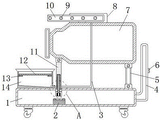
Fig. 1 is a schematic front view of a cross-sectional structure of the present invention;
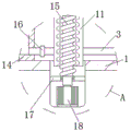
FIG. 2 is an enlarged schematic view of the structure at A in FIG. 1;
fig. 3 is a schematic front view of the present invention;
fig. 4 is a schematic top sectional view of the fixing block and the rotating plate in fig. 3.
In the figure: 1. a base; 2. a storage battery; 3. a connecting pipe; 4. a fixed mount; 5. a first connecting rod; 6. an integrated switch; 7. a draft tube; 8. a fixed block; 9. spraying a hole; 10. rotating the plate; 11. a second connecting rod; 12. a filter screen; 13. a limiting block; 14. a water collection tank; 15. a screw; 16. a water pump; 17. a limiting plate; 18. a first motor; 19. a gear; 20. a second motor; 21. a third connecting rod; 22. a flexible hose; 23. a fourth connecting rod; 24. a fifth connecting rod; 25. a-a fourth connecting rod; 26. b-a fourth connecting rod; 27. c-a fourth connecting rod.
Detailed Description
The technical solutions in the embodiments of the present invention will be described clearly and completely with reference to the accompanying drawings in the embodiments of the present invention, and it is obvious that the described embodiments are only some embodiments of the present invention, not all embodiments. Based on the embodiments in the present invention, all other embodiments obtained by a person skilled in the art without creative work belong to the protection scope of the present invention.
Referring to fig. 1-4, the utility model provides a pair of spray dust device on construction site, the last output shaft tip of first motor 18 passes through the bearing frame and installs in limiting plate 17's inboard, and limiting plate 17 is fixed in the inside relevant position department of base 1. Example (b):
the utility model provides a construction site spraying dust device, the on-line screen storage device comprises a base 1, base 1's top surface right-hand member department articulates there is vertical head rod 5, and head rod 5's top articulates there is draft tube 7, the left lower extreme of draft tube 7 articulates there is vertical second connecting rod 11, base 1 internal fixation has first motor 18, the inboard at limiting plate 17 is installed through the bearing frame to first motor 18's last output shaft tip, limiting plate 17 is fixed in the inside relevant position department of base 1, first motor 18's last output shaft tip fixed connection has upper portion to revolve and connects in the vertical screw rod 15 in second connecting rod 11 lower part, the external screw thread on screw rod 15 surface and the internal thread of second connecting rod 11 inner wall cooperate and use.
The battery 2 is installed to base 1's inside bottom, and base 1's right flank fixedly connected with mount 4, and the surface mounting of mount 4 has integrated switch 6, and first motor 18, second motor 20 and water pump 16 are supplied power by battery 2, and first motor 18, second motor 20 and water pump 16 are opened and close by integrated switch 6 control.
The top end of the draft tube 7 is fixed with a fixed block 8, a second motor 20 is fixedly mounted inside the fixed block 8, a gear 19 is fixedly connected to the end portion of an upper output shaft of the second motor 20, a horizontal third connecting rod 21 is hinged to the upper surface of the gear 19, a horizontal fourth connecting rod 23 is hinged to the left front side of the third connecting rod 21, the fourth connecting rod 23 comprises an A-fourth connecting rod 25 hinged to the left front end of the third connecting rod 21, the right front end of the A-fourth connecting rod 25 is respectively and integrally connected with a B-fourth connecting rod 26 and a C-fourth connecting rod 27, and a fifth connecting rod 24 is inserted into the inside of the right front end of the A-fourth connecting rod 25.
The upper end and the lower end of a fifth connecting rod 24 are fixed on the inner wall of a fixed block 8, the front ends of a B-fourth connecting rod 26 and a C-fourth connecting rod 27 are fixedly connected with a rotating plate 10, spray holes 9 are uniformly formed in the rotating plate 10, water can be uniformly sprayed through the spray holes 9, the rotating plate 10 and the gears 19 are arranged in two groups, the rotating plate 10 is of an arc-shaped structure, the range of spraying the spray holes 9 is enlarged due to the arc-shaped structure, the top end of the connecting pipe 3 is connected with a flexible hose 22, the inside of the flexible hose 22 is communicated with the inside of the rotating plate 10, the rotating plate 10 is located above a water collecting tank 14, the rotating plate 10 and the gears 19 are arranged in two groups, the rotating plate 10 is of an arc-shaped structure, the front gear 19 and the rear gear.
The working principle is as follows: when the device is used, the device is pushed to a proper position through the fixing frame 4, the integrated switch 6 is operated to control the water pump 16 and the second motor 20 to work, the water pump 16 conveys water in the water collecting tank 14 to the inside of the rotating plate 10 through the connecting pipe 3 and the telescopic hose 22, the water is sprayed out through the spray holes 9, the second motor 20 drives the gear 19 to rotate through the output shaft, the gear 19 rotates to drive the right side of the third connecting rod 21 to continuously move left and right, the gear 19 drives the other group of gears 19 to rotate through limiting of the fifth connecting rod 24, the left and right movement of the third connecting rod 21 drives the left side of the fourth connecting rod 23 to continuously move left and right so as to drive the rotating plate 10 to continuously rotate back and forth, the spraying range of the spray holes 9 is enlarged through the back and forth forward and reverse rotation of the.
The operation integrated switch 6 controls the first motor 18 to work again, the output shaft of the first motor 18 continuously rotates forwards and backwards, the first motor 18 drives the screw rod 15 to continuously rotate forwards and backwards through the output shaft, the screw rod 15 surface and the screw thread on the inner wall of the second connecting rod 11 are passed through, the screw rod 15 rotates to enable the height of the second connecting rod 11 to continuously lift so as to enable the height of the left side of the guide cylinder 7 to continuously lift, the spraying range of the device in the vertical direction is greatly increased, the spraying effect of the device is further improved, water drops sprayed by the spray holes 9 are collected in the water collecting tank 14, impurities in the water are filtered through the filter screen 12, the filter screen 12 can be taken away from the surface of the limiting block 13 to be replaced, the water in the water collecting tank 14 is extracted.
It is obvious to a person skilled in the art that the invention is not restricted to details of the above-described exemplary embodiments, but that it can be implemented in other specific forms without departing from the spirit or essential characteristics of the invention. The present embodiments are therefore to be considered in all respects as illustrative and not restrictive, the scope of the invention being indicated by the appended claims rather than by the foregoing description, and all changes which come within the meaning and range of equivalency of the claims are therefore intended to be embraced therein. Any reference sign in a claim should not be construed as limiting the claim concerned.
Claims (5)
1. The utility model provides a construction scene spraying dust device which characterized in that: comprises a base (1), a vertical first connecting rod (5) is hinged at the right end of the top surface of the base (1), a guide cylinder (7) is hinged at the top end of the first connecting rod (5), a vertical second connecting rod (11) is hinged at the left lower end of the guide cylinder (7), a first motor (18) is fixed in the base (1), the end part of an upper output shaft of the first motor (18) is fixedly connected with a vertical screw (15) of which the upper part is screwed in the lower part of the second connecting rod (11), a water collecting tank (14) with an opening at the top end is fixed at the left end of the top surface of the base (1), a connecting pipe (3) is connected at the bottom end of the right side of the water collecting tank (14), a water pump (16) is installed at the left side of the connecting pipe (3), a fixing block (8) is fixed at the top end of the guide cylinder (7), the end part of an upper output shaft of the second motor (20) is fixedly connected with a gear (19), the upper surface of the gear (19) is hinged with a horizontal third connecting rod (21), the left front side of the third connecting rod (21) is hinged with a horizontal fourth connecting rod (23), the fourth connecting rod (23) comprises an A-fourth connecting rod (25) hinged with the left front end of the third connecting rod (21), the right front end of the A-fourth connecting rod (25) is respectively and integrally connected with a B-fourth connecting rod (26) and a C-fourth connecting rod (27), a fifth connecting rod (24) is inserted into the inner part of the right front end of the A-fourth connecting rod (25), the upper end and the lower end of the fifth connecting rod (24) are fixed on the inner wall of the fixed block (8), the front ends of the B-fourth connecting rod (26) and the C-fourth connecting rod (27) are fixedly connected with a rotating plate (10), spray holes (9) are uniformly formed in the rotating plate (10), the top end of the connecting pipe (3) is connected with a flexible hose (22), the interior of the flexible hose (22) is communicated with the interior of the rotating plate (10), and the rotating plate (10) is located above the water collecting tank (14).
2. The spraying dust-settling device for the construction site according to claim 1, which is characterized in that: the rotary plate (10) and the gears (19) are both provided with two sets, the rotary plate (10) is of an arc-shaped structure, the front gear (19) and the rear gear (19) are meshed with each other, and the gears (19) on the rear side are rotatably connected with the fixed block (8).
3. The spraying dust-settling device for the construction site according to claim 1, which is characterized in that: the end part of an upper output shaft of the first motor (18) is arranged on the inner side of the limiting plate (17) through a bearing seat, and the limiting plate (17) is fixed at the corresponding position inside the base (1).
4. The spraying dust-settling device for the construction site according to claim 1, which is characterized in that: the storage battery (2) is installed to the inside bottom of base (1), the right flank fixedly connected with mount (4) of base (1), and the surface mounting of mount (4) has integrated switch (6), and first motor (18), second motor (20) and water pump (16) are supplied power by storage battery (2), and first motor (18), second motor (20) and water pump (16) are opened and close by integrated switch (6) control.
5. The spraying dust-settling device for the construction site according to claim 1, which is characterized in that: the water collecting tank is characterized in that limiting blocks (13) are respectively fixed at the upper parts of the left inner side wall and the right inner side wall of the water collecting tank (14), a horizontal filter screen (12) is further arranged in the water collecting tank (14), the filter screen (12) is arranged on the left limiting block (13) and the right limiting block (13), and the diameter of the filter screen (12) is matched with the inner diameter of the water collecting tank (14).
Priority Applications (1)
| Application Number | Priority Date | Filing Date | Title |
|---|---|---|---|
| CN202020703833.5U CN212039606U (en) | 2020-04-30 | 2020-04-30 | Construction site spraying dust-settling device |
Applications Claiming Priority (1)
| Application Number | Priority Date | Filing Date | Title |
|---|---|---|---|
| CN202020703833.5U CN212039606U (en) | 2020-04-30 | 2020-04-30 | Construction site spraying dust-settling device |
Publications (1)
| Publication Number | Publication Date |
|---|---|
| CN212039606U true CN212039606U (en) | 2020-12-01 |
Family
ID=73525473
Family Applications (1)
| Application Number | Title | Priority Date | Filing Date |
|---|---|---|---|
| CN202020703833.5U Active CN212039606U (en) | 2020-04-30 | 2020-04-30 | Construction site spraying dust-settling device |
Country Status (1)
| Country | Link |
|---|---|
| CN (1) | CN212039606U (en) |
Cited By (1)
| Publication number | Priority date | Publication date | Assignee | Title |
|---|---|---|---|---|
| CN113996134A (en) * | 2021-10-28 | 2022-02-01 | 濮阳职业技术学院 | Water-saving dust device for ecological environment protection |
-
2020
- 2020-04-30 CN CN202020703833.5U patent/CN212039606U/en active Active
Cited By (1)
| Publication number | Priority date | Publication date | Assignee | Title |
|---|---|---|---|---|
| CN113996134A (en) * | 2021-10-28 | 2022-02-01 | 濮阳职业技术学院 | Water-saving dust device for ecological environment protection |
Similar Documents
| Publication | Publication Date | Title |
|---|---|---|
| CN111691496B (en) | Anti-blocking type energy-saving rainwater self-collecting device for building based on rainwater potential energy driving | |
| CN212039606U (en) | Construction site spraying dust-settling device | |
| CN211124769U (en) | New forms of energy electronic information display device | |
| CN112076569A (en) | Dust device for municipal construction | |
| CN216475477U (en) | Hydraulic engineering environmental protection cistern | |
| CN214339111U (en) | Intelligence afforestation watering device | |
| CN113152382B (en) | But hydraulic engineering of automatically cleaning is with hiding inlet channel | |
| CN212866148U (en) | Green land is planted and is used rainwater supply structure | |
| CN217407175U (en) | Rainwater collecting and irrigating device for roof based on building ecological greening | |
| CN217267190U (en) | District property road sweeper | |
| CN216954985U (en) | Novel door and window processing water drenching for production device | |
| CN212487776U (en) | Automatic drip irrigation device for plant wall with rainwater collection function | |
| CN214125385U (en) | Monitoring mechanism of coal mine safety monitoring substation | |
| CN213527846U (en) | Mining equipment is with dust removal protection device that induced drafts | |
| CN211191142U (en) | Screen cloth cleaning device is used in colliery processing convenient to clearance | |
| CN215736204U (en) | Irrigation device for hydraulic engineering | |
| CN218680778U (en) | Landscape architecture engineering vertical irrigation device | |
| CN213715954U (en) | Building construction management device based on Internet of things | |
| CN218680751U (en) | Irrigation equipment is used in mountain body maintenance | |
| CN220936015U (en) | Irrigation equipment with rainwater collection function | |
| CN216254465U (en) | Irrigation equipment is used in energy-concerving and environment-protective of new forms of energy | |
| CN217157547U (en) | Self-cleaning expressway signboard | |
| CN217923965U (en) | Environment-friendly green building structure | |
| CN218175713U (en) | Regular maintenance device for highway construction | |
| CN218309437U (en) | Dust device that communication integration rack was used |
Legal Events
| Date | Code | Title | Description |
|---|---|---|---|
| GR01 | Patent grant | ||
| GR01 | Patent grant |