CN212038483U - Waste hemodialysis puncture needle processing box - Google Patents
Waste hemodialysis puncture needle processing box Download PDFInfo
- Publication number
- CN212038483U CN212038483U CN201820642144.0U CN201820642144U CN212038483U CN 212038483 U CN212038483 U CN 212038483U CN 201820642144 U CN201820642144 U CN 201820642144U CN 212038483 U CN212038483 U CN 212038483U
- Authority
- CN
- China
- Prior art keywords
- box body
- wall
- cutting blade
- processing box
- needle
- Prior art date
- Legal status (The legal status is an assumption and is not a legal conclusion. Google has not performed a legal analysis and makes no representation as to the accuracy of the status listed.)
- Active
Links
- 238000001631 haemodialysis Methods 0.000 title claims abstract description 74
- 230000000322 hemodialysis Effects 0.000 title claims abstract description 74
- 239000002699 waste material Substances 0.000 title claims abstract description 30
- 238000005520 cutting process Methods 0.000 claims abstract description 111
- 239000010813 municipal solid waste Substances 0.000 claims abstract description 29
- 238000005192 partition Methods 0.000 claims description 12
- 239000008280 blood Substances 0.000 claims description 7
- 210000004369 blood Anatomy 0.000 claims description 7
- 239000000853 adhesive Substances 0.000 claims 1
- 230000001070 adhesive effect Effects 0.000 claims 1
- 230000004888 barrier function Effects 0.000 claims 1
- 230000004308 accommodation Effects 0.000 description 27
- 238000000034 method Methods 0.000 description 10
- 238000000926 separation method Methods 0.000 description 9
- 239000002906 medical waste Substances 0.000 description 6
- 239000004743 Polypropylene Substances 0.000 description 4
- 238000000502 dialysis Methods 0.000 description 4
- 230000000474 nursing effect Effects 0.000 description 4
- -1 polypropylene Polymers 0.000 description 4
- 229920001155 polypropylene Polymers 0.000 description 4
- 230000000740 bleeding effect Effects 0.000 description 3
- 201000010099 disease Diseases 0.000 description 3
- 208000037265 diseases, disorders, signs and symptoms Diseases 0.000 description 3
- 208000015181 infectious disease Diseases 0.000 description 3
- 239000010781 infectious medical waste Substances 0.000 description 3
- 210000003141 lower extremity Anatomy 0.000 description 3
- 239000000463 material Substances 0.000 description 3
- VYPSYNLAJGMNEJ-UHFFFAOYSA-N Silicium dioxide Chemical compound O=[Si]=O VYPSYNLAJGMNEJ-UHFFFAOYSA-N 0.000 description 2
- 238000010586 diagram Methods 0.000 description 2
- 230000007613 environmental effect Effects 0.000 description 2
- 230000000266 injurious effect Effects 0.000 description 2
- 238000002161 passivation Methods 0.000 description 2
- 238000007789 sealing Methods 0.000 description 2
- 239000000741 silica gel Substances 0.000 description 2
- 229910002027 silica gel Inorganic materials 0.000 description 2
- 208000035473 Communicable disease Diseases 0.000 description 1
- 206010069803 Injury associated with device Diseases 0.000 description 1
- 208000012266 Needlestick injury Diseases 0.000 description 1
- 206010073310 Occupational exposures Diseases 0.000 description 1
- 206010052428 Wound Diseases 0.000 description 1
- 208000027418 Wounds and injury Diseases 0.000 description 1
- 238000005452 bending Methods 0.000 description 1
- 230000000903 blocking effect Effects 0.000 description 1
- 230000036772 blood pressure Effects 0.000 description 1
- 238000010276 construction Methods 0.000 description 1
- 230000006378 damage Effects 0.000 description 1
- 230000000694 effects Effects 0.000 description 1
- 230000002349 favourable effect Effects 0.000 description 1
- 230000023597 hemostasis Effects 0.000 description 1
- 208000014674 injury Diseases 0.000 description 1
- 238000004519 manufacturing process Methods 0.000 description 1
- 238000012986 modification Methods 0.000 description 1
- 230000004048 modification Effects 0.000 description 1
- 231100000675 occupational exposure Toxicity 0.000 description 1
- 238000002360 preparation method Methods 0.000 description 1
Images


Landscapes
- External Artificial Organs (AREA)
- Accommodation For Nursing Or Treatment Tables (AREA)
Abstract
The utility model provides a processing box for waste hemodialysis puncture needles, which comprises a processing box body, a processing box cover, a clapboard, a sharp machine box, a cutting blade base and a cutting blade, wherein the processing box body is divided into a hose accommodating space and a sharp machine box body accommodating space by the longitudinally arranged clapboard, a garbage bag fixing part is arranged on the inner wall of the hose accommodating space, the sharp machine box body is positioned in the sharp machine box body accommodating space, the wall surface of the sharp machine box body accommodating space is provided with a sharp machine box body inlet and outlet, the top of the clapboard is provided with a notch, the bottom of the notch is a horizontal plane used as a cutting surface, the cutting blade base is arranged at the position corresponding to the notch on the inner wall of the processing box cover, the cutting blade is detachably arranged on the cutting blade base, the cutting blade is vertical to the inner wall of the processing box cover, the direction of the cutting blade is, after the cover of the processing box is closed, the cutting edge of the cutting blade is contacted with the cutting surface.
Description
Technical Field
The utility model belongs to the field of medical equipment, a abandonment hemodialysis pjncture needle processing box is related to.
Background
At present, a commonly used hemodialysis puncture needle generally comprises a needle head, needle wings, a needle cylinder, a needle cap and a hose, wherein the front end of the needle cylinder is fixedly connected with the needle head, the needle wings are positioned on the outer surface of the front end of the needle cylinder, the hose is fixedly sleeved at the rear end of the needle cylinder, the length of the hose is generally 20-30 cm, the needle cap is sleeved on the needle head, and the needle head, the needle wings, the needle cylinder and the hose are inseparable.
Clinically, after hemodialysis is finished, a nurse firstly pulls out the hemodialysis puncture needle and then presses the puncture points of a patient to stop bleeding, and because the blood pressure of the two puncture points of the patient is high, after the hemodialysis puncture needle is pulled out, a nurse must firstly treat the puncture point, prick the tourniquet for hemostasis and then treat the pulled hemodialysis puncture needle, the puncture needle with bloodstains pulled out in the process is careless, an ideal treatment device is not provided, the nurse generally directly and naked puts the puncture needle used up by the patient on a bed unit, or the needle head is inserted into the matched needle cap, even the rope is directly lost on the ground to avoid the patients and nurses from being injured by the needle, but the occurrence of accidental needle-stick injuries can not be effectively avoided, meanwhile, the dripping bloodstain can cause pollution to the environment of the dialysis chamber, and especially the risk of contacting the exposed needle of the hemodialysis patient carrying infectious diseases is higher.
After a nurse presses a puncture point of a hemodialysis patient, the hemodialysis puncture needle with bloodstains is held by a hand and is placed into a medical sharp instrument box. Because a treatment unit only is equipped with a nursing treatment car, only has a sharp machine box on the car, and to hemodialysis pjncture needle, the pjncture needle quantity of pulling out is big, and sharp machine box's space is limited, and the hose behind the syringe needle has occupied most space of sharp machine box again, and this just needs frequently to change sharp machine box, and this not only increases nurse's work load, wastes sharp machine box moreover. If not in time changing sharp machine box in busy in-process, the hose stretches out and can cause the blood droplet to spatter outside sharp machine box, and the pjncture needle also can expose outside, and this has increased the needle stick again and has hindered the risk. The position of the nursing trolley is relatively fixed, a nurse needs to hold the dialysis needle used by hand to walk for a certain distance to the nursing trolley, the needle head is exposed outside in the walking process, blood stains are dripped and splashed, the environment is polluted, a patient and nursing staff who shuttle to and fro in a busy state are the groups which are easily injured by needle puncture in the process, and the occupational exposure and the risk of disease infection are increased. In addition, for the treatment of medical waste, the needle head of the hemodialysis puncture needle and the bloodline hose belong to the injurious waste and the infectious waste respectively, the treatment modes of the injurious waste and the infectious waste are different, and the sharp instruments put into the sharp instrument box cannot be reclassified, so that the treatment cost of the medical waste of the sharp instruments is increased, and the principle of classifying and treating the environmental protection waste is not met.
SUMMERY OF THE UTILITY MODEL
An object of the utility model is to overcome prior art's not enough, provide an abandonment hemodialysis pjncture needle treatment box to improve the security that abandonment hemodialysis pjncture needle was handled, and realize the classification of abandonment hemodialysis pjncture needle, reduce medical waste treatment cost.
The utility model provides a waste hemodialysis puncture needle treatment box, which comprises a treatment box body, a treatment box cover, a clapboard, a sharp instrument box, a hanging rope, a lock catch fixing block, a cutting blade base and a cutting blade, wherein the sharp instrument box comprises a sharp instrument box body and a sharp instrument box cover,
the upper end of the box body of the processing box is opened, the box body of the processing box is divided into a hose containing space and a sharp machine box body containing space by a longitudinally arranged clapboard, a garbage bag fixing part is arranged on the inner wall of the hose containing space, the sharp machine box body is positioned in the sharp machine box body containing space, one wall surface of the sharp machine box body containing space is provided with a sharp machine box body inlet and outlet, the shape of the sharp machine box body is matched with that of the sharp machine box body containing space, a movable baffle is arranged at the inlet and outlet of the sharp machine box body, the top of the clapboard is provided with a gap, the bottom of the gap is a horizontal plane used as a cutting surface, a hanging rope is arranged on the box body of the processing box, a lock catch fixing block is arranged on the outer wall of the box cover of the processing box, a base is arranged at the position, which corresponds to the gap, the direction of cutting blade is unanimous with the direction of baffle, handles the box body and handles box lid and articulate as an organic whole, handles box lid closed back, and cutting blade's blade contacts with the cutting plane.
In the technical scheme of the waste hemodialysis puncture needle processing box, one side, close to the box body accommodating space of the sharp instrument box, on the cutting surface is provided with a plurality of mutually parallel convex blocks for fixing the waste hemodialysis puncture needle, and a gap between every two adjacent convex blocks is matched with the outer diameter of a hose of the hemodialysis puncture needle. Preferably, the gap between the cutting blade and the bump is not more than 2mm after the cover of the process cartridge is closed. Under the circumstances that cutting plane has set up the lug, it promotes the piece to be equipped with the syringe needle on the processing box lid inner wall to be preferred, and the syringe needle promotes the piece and is parallel to each other with cutting blade, and the syringe needle promotes the distance between piece and the cutting blade and is 1 ~ 3cm, and the syringe needle promotes the lower limb of piece and is parallel with cutting blade's blade, handles the box lid closed back, and the syringe needle promotes the piece and is located sharp ware box body accommodation space's top. The design of this structure can increase the stability that abandonment hemodialysis pjncture needle was placed on the cutting plane, prevents to be greater than the syringe needle section because of the length and the weight of hose section and leads to whole pjncture needle to fall into hose accommodation space, guarantees simultaneously that the syringe needle section of downcutting falls into sharp ware box body smoothly.
Among the above-mentioned technical scheme of abandonment hemodialysis pjncture needle treatment box, be equipped with the handle on the outer wall of treatment box lid, the handle sets up on the lid outer wall that the cutting blade base that the position corresponds with the lid inner wall is best, and cutting blade is more laborsaving during the cutting like this, more stable.
Among the above-mentioned technical scheme of abandonment hemodialysis pjncture needle processing box, be equipped with the soft separation blade that is used for preventing blood when cutting to splash on the processing box lid inner wall and preferably adopt the silica gel preparation, the high blade 2 ~ 5mm that is less than cutting blade of best of soft separation blade.
In the technical scheme of the waste hemodialysis puncture needle processing box, the movable baffle arranged at the entrance and the exit of the box body of the sharp instrument box is bonded with the outer wall of the box body of the processing box through the sticking buckle.
Among the above-mentioned technical scheme of abandonment hemodialysis pjncture needle processing box, the width w of cutting plane is 1 ~ 2cm, and the thickness and the intensity of baffle need not take place bending deformation when guaranteeing the cutting, and the material of baffle can adopt polypropylene, and the baffle can adopt the flat board that thickness is 1 ~ 2cm and thickness uniformity, also can adopt the thin baffle of upper end of lower extreme, and the width that the cutting plane will be guaranteed to upper end thickness is 1 ~ 2 cm.
Among the above-mentioned technical scheme of abandonment hemodialysis pjncture needle processing box, hose accommodation space is greater than sharp machine box body accommodation space, and hose accommodation space's volume is preferred to be 3 times at least sharp machine box body accommodation space.
Among the above-mentioned technical scheme of abandonment hemodialysis pjncture needle processing box, the disposal bag mounting is flat, and the disposal bag mounting passes through the bracing piece to be fixed on the inner wall of hose accommodation space.
According to the technical scheme of the waste hemodialysis puncture needle processing box, a sharp instrument box cover is fixed on a sharp instrument box body in a clamping mode; the outer wall of the processing box body is provided with a fixing clamp for fixing the sharp instrument box cover, and the sharp instrument box cover is fixed on the outer wall of the processing box body through the fixing clamp.
The utility model provides a use method of abandonment hemodialysis pjncture needle processing box as follows:
before the treatment box is used, a medical garbage bag is sleeved in the soft accommodating space of the treatment box and is fixed on the garbage bag fixing piece by using a clamp. In the dialysis process of a patient, the treatment box is not needed to be used, the box cover of the treatment box is closed and buckled with the lock catch, and the treatment box is placed under a sickbed or hung on the sickbed, so that the sickroom space is saved, and the treatment box is prevented from being kicked over by medical care personnel or the patient and family members thereof. After patient hemodialysis, the nurse arranges this processing box in bedside cupboard or on the ground earlier, open the processing box lid, extract the hemodialysis pjncture needle, the puncture point of patient is pushed down on the one hand, the hemodialysis pjncture needle that will take off is put into processing box on the other hand, make the syringe needle towards the sharp ware accommodation space of processing box, soft being located hose accommodation space, make the joint department of cylinder and hose take on the cutting plane of baffle, be equipped with under the condition of lug on the cutting plane, the hose card that will be close to the joint department of cylinder and hose realizes fixing between two adjacent lugs, then handle patient's puncture point, prick and press the tourniquet to stop bleeding well. After the tourniquet is pricked, the box cover of the treatment box is closed, the cutting blade can cut off the hose close to the joint of the needle cylinder and the hose when the box cover of the treatment box is closed, the hose falls into a garbage bag with a soft containing space, the needle head together with the needle cylinder and the needle wing falls into the sharp instrument box body in the containing space of the sharp instrument box body, and under the condition that the lug is arranged on the cutting surface, the needle head together with the needle cylinder and the needle wing falls into the sharp instrument box body under the pushing of the needle head pushing blade. After each use, the cover of the processing box is closed and the lock catch is buckled, and the processing box is placed under a sickbed or hung on the sickbed and then opened when in use. After soft accommodation space's disposal bag was filled with, take out and replace new disposal bag, sharp machine box among the sharp machine box body accommodation space fills with the back, open adjustable fender, take out sharp machine box body, take off sharp machine box lid and on sharp machine box body, with sharp machine box lid and sharp machine box body joint back centralized processing, put into new sharp machine box body in the sharp machine box body accommodation space of handling the box, continue to use, along with the increase of handling capacity, change new cutting blade after the cutting blade passivation.
Compared with the prior art, the utility model discloses following profitable technological effect has been produced:
1. the utility model provides a abandonment hemodialysis pjncture needle processing box has designed the structure with the soft and syringe needle cutting separation and the categorised collection of pjncture needle, this aspect can avoid to occupy box body space big because of using the hose that medical sharp machine box collected the abandonment pjncture needle existence, the problem of medical sharp machine box space of can not make full use of and extravagant medical sharp machine box, on the other hand has also reduced and has used medical sharp machine and can't realize categorised and unable sharp machine box space that makes full use of to the abandonment pjncture needle and the uncovered and hose blood droplet spatter the stab that causes and the disease infection risk, can realize in the categorised collection of infectious medical waste and damaging medical waste simultaneously, be favorable to the separation treatment of better realization medical waste, reduce medical waste's treatment cost, accord with the principle of environmental protection rubbish separation processing more like this.
2. The utility model provides an abandonment hemodialysis pjncture needle treatment box has designed and has hung the rope, can hang on the sick bed when not using, takes off during the use and arranges bedside cupboard or on the ground in, realizes just using near the sick bed, and this also can reduce the puncture wound and the disease infection risk.
3. The utility model provides a waste puncture needle of box is handled to abandonment hemodialysis pjncture needle places, the cutting structure, the closure of lid and fixed mode all are applicable to user one-hand operation, can satisfy medical personnel to the requirement that the patient that dialyses finished stanchs the operation and handle the abandonment pjncture needle.
4. The utility model provides a processing box is handled to abandonment hemodialysis pjncture needle is applicable to the processing of abandonment transfusion system, blood transfusion ware etc. except being applicable to the processing of abandonment hemodialysis pjncture needle, simple structure, and easy manufacturing is also suitable for popularization and application.
Drawings
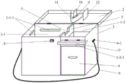
FIG. 1 is a schematic view of a waste hemodialysis needle cartridge according to the present invention;
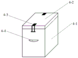
FIG. 2 is a schematic view of the construction of the sharps container;
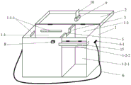
FIG. 3 is a schematic view of the cartridge of FIG. 1 shown in a configuration without the cartridge being placed in a sharps container;
fig. 4 is a second schematic structural view of the waste hemodialysis needle cartridge of the present invention;
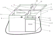
fig. 5 is a third schematic structural view of the waste hemodialysis needle treatment cartridge of the present invention;
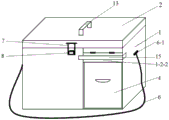
FIG. 6 is a schematic view of the external structure of the waste hemodialysis needle cartridge of the present invention;
FIG. 7 is a partial schematic view (top view) of a trash bag retainer disposed on an inner wall of the hose receiving space;
FIG. 8 is a top view of the separator plate;
in the figure, 1-a processing box body, 1-1-a hose containing space, 1-1-1-a garbage bag fixing part, 1-1-2-a supporting rod, 1-2-a sharp device box body containing space, 1-2-1-a sharp device box body inlet and outlet, 1-2-a movable baffle, 2-a processing box cover, 3-a clapboard, 4-a sharp device box, 4-1-a sharp device box body, 4-2-a sharp device box cover, 4-3-a buckle and 4-a handle, 5-cutting surface, 6-hanging rope, 6-1-hanging lug, 7-lock catch, 8-lock catch fixing block, 9-cutting blade base, 10-cutting blade, 11-lug, 12-needle head pushing piece, 13-handle, 14-soft blocking piece, 15-sticking buckle and w-width of cutting surface.
Detailed Description
The following will further explain the waste hemodialysis needle treatment cartridge and the method of using the same provided by the present invention by embodiments with reference to the drawings. It is necessary to point out that the following examples are only used for further illustration of the present invention, and should not be construed as limiting the scope of the present invention, and those skilled in the art can implement the present invention by making some non-essential improvements and modifications according to the above-mentioned contents of the present invention, and still fall within the scope of the protection of the present invention.
Example 1
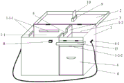
In this embodiment, the configuration of the disposal hemodialysis needle cartridge is schematically shown in FIG. 1, the appearance thereof is schematically shown in FIG. 6, the configuration of the disposal cartridge when the sharps container is not loaded is schematically shown in FIG. 3, the waste hemodialysis puncture needle processing box comprises a processing box body 1, a processing box cover 2, a clapboard 3, a sharp instrument box 4, a hanging rope 6, a lock catch 7, a lock catch fixing block 8, a cutting blade base 9 and a cutting blade 10, wherein the sharp instrument box 4 comprises a sharp instrument box body 4-1 and a sharp instrument box cover 4-2, two buckles 4-3 are arranged on the outer wall close to the opening end of the sharp instrument box body 4-1, the buckles 4-3 are matched with buckle clamping parts on the sharp instrument box cover 4-2 to realize the clamping connection of the sharp instrument box cover and the sharp instrument box body 4-1, and a handle 4-4 is arranged on the outer wall of the sharp instrument box body 4-1.
The box body of the processing box is in a cuboid shape, the upper end of the box body of the processing box is opened, the box body is divided into a hose accommodating space 1-1 and a sharp device box body accommodating space 1-2 by a longitudinally arranged partition plate 3 made of polypropylene with the thickness of 1.0cm, the hose accommodating space 1-1 is larger than the sharp device box body accommodating space 1-2, the inner wall of the hose accommodating space is provided with a garbage bag fixing part 1-1-1, the garbage bag fixing part 1-1-1 is in a flat plate shape, the garbage bag fixing part 1-1-1 is fixed on the inner wall of the hose accommodating space through a support rod, three garbage bag fixing parts are fixed on the inner wall of the box body through the support rod, one garbage bag fixing part is fixed on the partition plate through the support rod, as shown in figure 7, the sharp device box body 4-1 is positioned in the sharp device box, the wall surface of the sharp instrument box body containing space right in front is provided with a rectangular sharp instrument box body access 1-2-1, the shape of the sharp instrument box body is cuboid, the shape and the size of a sharp instrument box body 4-1 are matched with the shape and the size of the sharp instrument box body containing space 1-2, the access 1-2-1 of the sharp instrument box body is provided with a movable baffle 1-2-2, the upper end of the movable baffle is hinged with the processing box body, the movable baffle 1-2-2 is provided with a sticking buckle 15, the movable baffle is mutually bonded with the sticking buckle arranged on the outer wall of the processing box body through the sticking buckle, when the movable baffle is bonded with the processing box body, fix sharp machine box body in sharp machine box body accommodation space, when adjustable fender did not bond with processing box body, can take out sharp machine box body from sharp machine box body accommodation space. The top of the partition plate 3 is provided with a rectangular notch, the bottom of the notch is a horizontal plane serving as a cutting surface 5, the width w of the cutting surface is 1cm, the left outer side wall and the right outer side wall of the box body of the processing box are respectively provided with a hanging lug 6-1, two ends of a hanging rope 6 are respectively connected with the two hanging lugs and fixed on the box body of the processing box, and the outer wall of the front side of the box body of the processing box is provided with a lock catch fixing block. The outer wall of the processing box body is provided with a fixing clamp for fixing the cover of the sharp instrument box, and the cover of the sharp instrument box is clamped on the outer wall of the processing box body through the fixing clamp.
The processing box lid is lower extreme open-ended cuboid, the shape of processing box lid open end matches with processing box body upper end open-ended shape, be equipped with the hasp 7 that the position corresponds with the hasp fixed block that handles on the box body on the processing box lid outer wall, the hasp is detained and can be realized abandonment hemodialysis pjncture needle processing box's sealed on the hasp fixed block, be equipped with handle 13 on the processing box lid outer wall, processing box lid inner wall is equipped with cutting blade base 9 with breach department of correspondence, cutting blade 10 installs on cutting blade base with the detachable mode, cutting blade 10 is perpendicular to and is handled box lid inner wall, cutting blade 10's direction is unanimous with the direction of baffle, it is as an organic whole with processing box lid 2 is articulated to handle box body 1, handle box lid closed back.
Example 2
In this embodiment, a schematic structural diagram of the waste hemodialysis puncture needle processing box is shown in fig. 4, an appearance structure of the waste hemodialysis puncture needle processing box is shown in fig. 6, the waste hemodialysis puncture needle processing box includes a processing box body 1, a processing box cover 2, a partition plate 3, a sharp machine box 4, a hanging rope 6, a lock catch 7, a lock catch fixing block 8, a cutting blade base 9 and a cutting blade 10, the sharp machine box 4 includes a sharp machine box body 4-1 and a sharp machine box cover 4-2, two buckles 4-3 are arranged on an outer wall close to an opening end of the sharp machine box body 4-1, the buckles 4-3 are matched with a buckle clamping portion on the sharp machine box cover 4-2 to realize clamping of the sharp machine box cover and the sharp machine box body 4-1, and a handle 4-4 is arranged on an outer wall of the sharp machine box body 4.
The box body of the treatment box is in a cuboid shape, the upper end of the box body of the treatment box is opened, the box body is divided into a hose accommodating space 1-1 and a sharp device box body accommodating space 1-2 by a partition plate 3 which is longitudinally arranged and made of polypropylene material, the hose accommodating space 1-1 is larger than the sharp device box body accommodating space 1-2, the inner wall of the hose accommodating space is provided with a garbage bag fixing part 1-1-1, the garbage bag fixing part 1-1-1 is in a flat plate shape, the garbage bag fixing part 1-1-1 is fixed on the inner wall of the hose accommodating space through a support rod 1-1-2, three garbage bag fixing parts are fixed on the inner wall of the box body through the support rod, one garbage bag fixing part is fixed on the partition plate through the support rod, as shown in figure 7, the sharp device box body 4-, the wall surface of the sharp instrument box body containing space right in front is provided with a rectangular sharp instrument box body access 1-2-1, the shape of the sharp instrument box body is cuboid, the shape and the size of a sharp instrument box body 4-1 are matched with the shape and the size of the sharp instrument box body containing space 1-2, the access 1-2-1 of the sharp instrument box body is provided with a movable baffle 1-2-2, the upper end of the movable baffle is hinged with the processing box body, the movable baffle 1-2-2 is provided with a sticking buckle 15, the movable baffle is mutually bonded with the sticking buckle arranged on the outer wall of the processing box body through the sticking buckle, when the movable baffle is bonded with the processing box body, fix sharp machine box body in sharp machine box body accommodation space, when adjustable fender did not bond with processing box body, can take out sharp machine box body from sharp machine box body accommodation space. The top of baffle 3 is equipped with the rectangle breach, the bottom of breach is the horizontal plane as cutting plane 5, the baffle is thin flat board of going up thick down, baffle lower extreme thickness is 1cm, upper end thickness is 2cm, therefore the width w of cutting plane is close 2cm, one side that is close to sharp ware box body accommodation space 1-2 on cutting plane 5 is equipped with a plurality of cuboid lugs 11 that are parallel to each other, are used for fixed abandonment hemodialysis pjncture needle, the clearance between the adjacent lug matches with the hose external diameter of hemodialysis pjncture needle, as shown in figure 8. The left outer side wall and the right outer side wall of the box body of the processing box are respectively provided with a hanging lug 6-1, two ends of a hanging rope 6 are respectively connected with the two hanging lugs and fixed on the box body of the processing box, and the outer wall of the front side of the box body of the processing box is provided with a lock catch fixing block 8. The outer wall of the processing box body is provided with a fixing clamp for fixing the cover of the sharp instrument box, and the cover of the sharp instrument box is clamped on the outer wall of the processing box body through the fixing clamp.
The box cover of the processing box is a cuboid with an opening at the lower end, the shape of the opening end of the box cover of the processing box is matched with the shape of the opening at the upper end of the box body of the processing box, the outer wall of the box cover of the processing box is provided with a lock catch 7 with the position corresponding to a lock catch fixing block on the box body of the processing box, the lock catch is buckled on the lock catch fixing block to realize the sealing of the processing box with the waste hemodialysis puncture needle, the outer wall of the box cover of the processing box is provided with a handle 13, the inner wall of the box cover of the processing box is provided with a cutting blade base 9 corresponding to a gap, a cutting blade 10 is detachably arranged on the cutting blade base, the cutting blade 10 is vertical to the inner wall, the cutting edge of the cutting blade is in contact with the cutting surface, and the clearance between the cutting blade and the bump is not more than 2 mm. Be equipped with the syringe needle of rectangle and promote piece 12 on 2 inner walls of processing box lid, the syringe needle promotes piece and cutting blade and is parallel to each other, and the syringe needle promotes the distance between piece and the cutting blade and is 2cm, and the syringe needle promotes the lower limb of piece and is parallel with cutting blade's blade, handles box lid closed back, and the syringe needle promotes the piece and is located sharp machine box body accommodation space's top.
Example 3
In this embodiment, a schematic structural diagram of the waste hemodialysis puncture needle processing box is shown in fig. 5, an appearance structure of the waste hemodialysis puncture needle processing box is shown in fig. 6, the waste hemodialysis puncture needle processing box includes a processing box body 1, a processing box cover 2, a partition plate 3, a sharp machine box 4, a hanging rope 6, a lock catch 7, a lock catch fixing block 8, a cutting blade base 9 and a cutting blade 10, the sharp machine box 4 includes a sharp machine box body 4-1 and a sharp machine box cover 4-2, two buckles 4-3 are arranged on an outer wall close to an opening end of the sharp machine box body 4-1, the buckles 4-3 are matched with a buckle clamping portion on the sharp machine box cover 4-2 to realize clamping of the sharp machine box cover and the sharp machine box body 4-1, and a handle 4-4 is arranged on an outer wall of the sharp machine box body 4.
The box body of the treatment box is in a cuboid shape, the upper end of the box body of the treatment box is opened, the box body is divided into a hose accommodating space 1-1 and a sharp device box body accommodating space 1-2 by a partition plate 3 which is longitudinally arranged and made of polypropylene material, the hose accommodating space 1-1 is larger than the sharp device box body accommodating space 1-2, the inner wall of the hose accommodating space is provided with a garbage bag fixing part 1-1-1, the garbage bag fixing part 1-1-1 is in a flat plate shape, the garbage bag fixing part 1-1-1 is fixed on the inner wall of the hose accommodating space through a support rod 1-1-2, three garbage bag fixing parts are fixed on the inner wall of the box body through the support rod, one garbage bag fixing part is fixed on the partition plate through the support rod, as shown in figure 7, the sharp device box body 4-, the wall surface of the sharp instrument box body containing space right in front is provided with a rectangular sharp instrument box body access 1-2-1, the shape of the sharp instrument box body is cuboid, the shape and the size of a sharp instrument box body 4-1 are matched with the shape and the size of the sharp instrument box body containing space 1-2, the access 1-2-1 of the sharp instrument box body is provided with a movable baffle 1-2-2, the upper end of the movable baffle is hinged with the processing box body, the movable baffle 1-2-2 is provided with a sticking buckle 15, the movable baffle is mutually bonded with the sticking buckle arranged on the outer wall of the processing box body through the sticking buckle, when the movable baffle is bonded with the processing box body, fix sharp machine box body in sharp machine box body accommodation space, when adjustable fender did not bond with processing box body, can take out sharp machine box body from sharp machine box body accommodation space. The top of baffle 3 is equipped with the rectangle breach, the bottom of breach is the horizontal plane as cutting plane 5, the baffle is thin flat board of going up thick down, baffle lower extreme thickness is 1cm, upper end thickness is 2cm, therefore the width w of cutting plane is close 2cm, one side that is close to sharp ware box body accommodation space 1-2 on cutting plane 5 is equipped with a plurality of cuboid lugs 11 that are parallel to each other, are used for fixed abandonment hemodialysis pjncture needle, the clearance between the adjacent lug matches with the hose external diameter of hemodialysis pjncture needle, as shown in figure 8. The left outer side wall and the right outer side wall of the box body of the processing box are respectively provided with a hanging lug 6-1, two ends of a hanging rope 6 are respectively connected with the two hanging lugs and fixed on the box body of the processing box, and the outer wall of the front side of the box body of the processing box is provided with a lock catch fixing block 8. The outer wall of the box body of the processing box is provided with a fixing clamp for fixing the cover of the sharp instrument box, and the cover of the sharp instrument box is clamped on the outer wall of the box body of the processing box through the fixing clamp before use.
The box cover of the processing box is a cuboid with an opening at the lower end, the shape of the opening end of the box cover of the processing box is matched with the shape of the opening at the upper end of the box body of the processing box, the outer wall of the box cover of the processing box is provided with a lock catch 7 with the position corresponding to a lock catch fixing block on the box body of the processing box, the lock catch is buckled on the lock catch fixing block to realize the sealing of the processing box with the waste hemodialysis puncture needle, the outer wall of the box cover of the processing box is provided with a handle 13, the inner wall of the box cover of the processing box is provided with a cutting blade base 9 corresponding to a gap, a cutting blade 10 is detachably arranged on the cutting blade base, the cutting blade 10 is vertical to the inner wall, the cutting edge of the cutting blade is in contact with the cutting surface, and the clearance between the cutting blade and the bump is not more than 2 mm. Be equipped with the syringe needle of rectangle and promote piece 12 on 2 inner walls of processing box lid, the syringe needle promotes piece and cutting blade and is parallel to each other, and the syringe needle promotes the distance between piece and the cutting blade and is 2cm, and the syringe needle promotes the lower limb of piece and is parallel with cutting blade's blade, handles box lid closed back, and the syringe needle promotes the piece and is located sharp machine box body accommodation space's top. Be equipped with the soft separation blade 14 that blood splashes when being used for preventing the cutting on the processing box lid inner wall of cutting blade base side, soft separation blade is arc open end towards the articulated department of processing box lid and processing box body, and half surrounds the cutting blade base, and soft separation blade is made by silica gel, and the height of soft separation blade is less than cutting blade's cutting edge 2 ~ 5 mm.
Example 4
In the present example, the methods of using the waste hemodialysis needle cartridges provided in examples 1 to 3 will be described.
Before the treatment box is used, a medical garbage bag is sleeved in the soft accommodating space of the treatment box and is fixed on the garbage bag fixing piece by using a clamp. In the dialysis process of a patient, the treatment box is not needed to be used, the box cover of the treatment box is closed and buckled with the lock catch, and the treatment box is placed under a sickbed or hung on the sickbed, so that the sickroom space is saved, and the treatment box is prevented from being kicked over by medical care personnel or the patient and family members thereof. After patient hemodialysis, the nurse arranges this processing box in bedside cupboard or on the ground earlier, open the processing box lid, extract the hemodialysis pjncture needle, the puncture point of patient is pushed down on the one hand, the hemodialysis pjncture needle that will take off is put into processing box on the other hand, make the syringe needle towards the sharp ware accommodation space of processing box, soft being located hose accommodation space, make the joint department of cylinder and hose take on the cutting plane of baffle, be equipped with under the condition of lug on the cutting plane, the hose card that will be close to the joint department of cylinder and hose realizes fixing between two adjacent lugs, then handle patient's puncture point, prick and press the tourniquet to stop bleeding well. After the tourniquet is pricked, the box cover of the treatment box is closed, the cutting blade can cut off the hose close to the joint of the needle cylinder and the hose when the box cover of the treatment box is closed, the hose falls into a garbage bag with a soft containing space, the needle head together with the needle cylinder and the needle wing falls into the sharp instrument box body in the containing space of the sharp instrument box body, and under the condition that the lug is arranged on the cutting surface, the needle head together with the needle cylinder and the needle wing falls into the sharp instrument box body under the pushing of the needle head pushing blade. After each use, the cover of the processing box is closed and the lock catch is buckled, and the processing box is placed under a sickbed or hung on the sickbed and then opened when in use. After soft accommodation space's disposal bag was filled with, take out and replace new disposal bag, sharp machine box among the sharp machine box body accommodation space fills with the back, open adjustable fender, take out sharp machine box body, take off sharp machine box lid and on sharp machine box body, with sharp machine box lid and sharp machine box body joint back centralized processing, put into new sharp machine box body in the sharp machine box body accommodation space of handling the box, continue to use, along with the increase of handling capacity, change new cutting blade after the cutting blade passivation.
Claims (10)
1. A waste hemodialysis puncture needle processing box is characterized by comprising a processing box body (1), a processing box cover (2), a partition plate (3), a sharp instrument box (4), a hanging rope (6), a lock catch (7), a lock catch fixing block (8), a cutting blade base (9) and a cutting blade (10), wherein the sharp instrument box (4) comprises a sharp instrument box body (4-1) and a sharp instrument box cover (4-2),
the upper end of the box body of the processing box is opened, the box body of the processing box is divided into a hose containing space (1-1) and a sharp machine box body containing space (1-2) by a partition plate (3) which is longitudinally arranged, a garbage bag fixing part (1-1-1) is arranged on the inner wall of the hose containing space, the sharp machine box body (4-1) is positioned in the sharp machine box body containing space (1-2), one wall surface of the sharp machine box body containing space is provided with a sharp machine box body inlet and outlet (1-2-1), the shape of the sharp machine box body (4-1) is matched with that of the sharp machine box body containing space (1-2), a movable baffle plate (1-2-2) is arranged at the sharp machine box body inlet and outlet (1-2-1), the top of the partition plate (3) is provided with a notch, and the bottom of the notch is a horizontal plane as, be equipped with on the processing box body and hang rope (6), be equipped with hasp fixed block (8) on the processing box body outer wall, be equipped with hasp (7) on the processing box lid outer wall, processing box lid inner wall is equipped with cutting blade base (9) with breach correspondence department, cutting blade (10) are installed on cutting blade base with the detachable mode, cutting blade (10) perpendicular to processing box lid inner wall, the direction of cutting blade (10) is unanimous with the direction of baffle, processing box body (1) and processing box lid (2) are articulated as an organic whole, processing box lid is closed back, cutting blade's blade contacts with the cutting plane.
2. The spent hemodialysis needle cartridge according to claim 1, wherein a plurality of protrusions (11) for fixing the spent hemodialysis needle are provided in parallel on the cutting surface (5) at a side close to the cartridge body receiving space (1-2) of the sharps cartridge, and a gap between the adjacent protrusions is matched with an outer diameter of a hose of the hemodialysis needle.
3. The waste hemodialysis puncture needle treatment box according to claim 2, wherein a needle head pushing piece (12) is provided on an inner wall of the treatment box cover (2), the needle head pushing piece and the cutting blade are parallel to each other, the distance between the needle head pushing piece and the cutting blade is 1-3 cm, the lower edge of the needle head pushing piece is parallel to the cutting edge of the cutting blade, and the needle head pushing piece is located above the box body accommodating space of the sharps box after the treatment box cover is closed.
4. The spent hemodialysis needle cartridge according to any one of claims 1 to 3, wherein a handle (13) is provided on an outer wall of the cartridge cover.
5. The used hemodialysis puncture needle cartridge according to any one of claims 1 to 3, wherein a soft flap (14) for preventing blood from splashing during cutting is provided on an inner wall of a cartridge cover.
6. The used hemodialysis puncture needle cartridge according to any one of claims 1 to 3, wherein the movable barrier (1-2-2) provided at the inlet/outlet (1-2-1) of the cartridge body of the sharps cartridge is adhered to the outer wall of the cartridge body of the cartridge by an adhesive button (15).
7. The spent hemodialysis needle cartridge according to any one of claims 1 to 3, wherein the width (w) of the cut surface is 1 to 2 cm.
8. The spent hemodialysis needle cartridge according to any one of claims 1 to 3, wherein the hose accommodating space (1-1) is larger than the sharps cartridge accommodating space (1-2).
9. The spent hemodialysis needle cartridge according to any one of claims 1 to 3, wherein the garbage bag holder (1-1-1) has a flat plate shape, and the garbage bag holder (1-1-1) is fixed to an inner wall of the hose receiving space by means of a support rod (1-1-2).
10. The discarded hemodialysis needle cartridge according to any one of claims 1 to 3, wherein the sharp machine cartridge cover (4-2) is fixed to the sharp machine cartridge body (4-1) by snap-fitting; the outer wall of the processing box body is provided with a fixing clamp for fixing the sharp instrument box cover, and the sharp instrument box cover is fixed on the outer wall of the processing box body through the fixing clamp.
Priority Applications (1)
| Application Number | Priority Date | Filing Date | Title |
|---|---|---|---|
| CN201820642144.0U CN212038483U (en) | 2018-05-02 | 2018-05-02 | Waste hemodialysis puncture needle processing box |
Applications Claiming Priority (1)
| Application Number | Priority Date | Filing Date | Title |
|---|---|---|---|
| CN201820642144.0U CN212038483U (en) | 2018-05-02 | 2018-05-02 | Waste hemodialysis puncture needle processing box |
Publications (1)
| Publication Number | Publication Date |
|---|---|
| CN212038483U true CN212038483U (en) | 2020-12-01 |
Family
ID=73507307
Family Applications (1)
| Application Number | Title | Priority Date | Filing Date |
|---|---|---|---|
| CN201820642144.0U Active CN212038483U (en) | 2018-05-02 | 2018-05-02 | Waste hemodialysis puncture needle processing box |
Country Status (1)
| Country | Link |
|---|---|
| CN (1) | CN212038483U (en) |
Cited By (1)
| Publication number | Priority date | Publication date | Assignee | Title |
|---|---|---|---|---|
| CN113229951A (en) * | 2021-05-07 | 2021-08-10 | 青岛市城阳区人民医院 | Medical portable sharp machine box of holding |
-
2018
- 2018-05-02 CN CN201820642144.0U patent/CN212038483U/en active Active
Cited By (1)
| Publication number | Priority date | Publication date | Assignee | Title |
|---|---|---|---|---|
| CN113229951A (en) * | 2021-05-07 | 2021-08-10 | 青岛市城阳区人民医院 | Medical portable sharp machine box of holding |
Similar Documents
| Publication | Publication Date | Title |
|---|---|---|
| CN107928936A (en) | A kind of medical staff's medical vehicle | |
| CN206852659U (en) | A kind of integrated rescue carrigae | |
| CN212038483U (en) | Waste hemodialysis puncture needle processing box | |
| CN209827377U (en) | Nursing vehicle | |
| CN210365393U (en) | Novel sharp machine box of cutting pipeline | |
| CN208677812U (en) | A kind of medical staff's medical vehicle | |
| CN207236947U (en) | A kind of transfusion vehicle with treatment of!medical waste equipment | |
| CN213346011U (en) | Home nursing home visit box | |
| CN212789043U (en) | Portable nursing tool case | |
| CN204932112U (en) | A kind of ABS transfusion vehicle with classification medical waste box | |
| CN211536030U (en) | Medical waste collection box | |
| CN214968305U (en) | Treatment plate | |
| CN215192316U (en) | Sharp machine processing table for operating room | |
| CN213722471U (en) | Large-capacity multifunctional treatment disc | |
| CN218075579U (en) | Novel nursing dressing bag | |
| CN218165380U (en) | Improvement type treatment dish of rubbish can be dealt with in classification | |
| CN206138209U (en) | Medical chamber with multiple functions | |
| CN220899041U (en) | Anti-drop treatment car | |
| CN213787838U (en) | Anesthesia medicine tray for anesthesia specialty | |
| CN213851689U (en) | Diabetes patient is with multi-functional nursing tray | |
| CN110584793A (en) | Push-pull PICC maintenance box of going out a doctor | |
| CN213406753U (en) | Disposable infusion nursing bag | |
| CN221266841U (en) | Portable sharp instrument box | |
| CN214806337U (en) | Portable detachable double-layer treatment disc | |
| CN219207832U (en) | Auxiliary tray for wound nursing |
Legal Events
| Date | Code | Title | Description |
|---|---|---|---|
| GR01 | Patent grant | ||
| GR01 | Patent grant |