CN212019422U - Boring cutter bar device for machining inner hole clamp spring groove - Google Patents
Boring cutter bar device for machining inner hole clamp spring groove Download PDFInfo
- Publication number
- CN212019422U CN212019422U CN202020456676.2U CN202020456676U CN212019422U CN 212019422 U CN212019422 U CN 212019422U CN 202020456676 U CN202020456676 U CN 202020456676U CN 212019422 U CN212019422 U CN 212019422U
- Authority
- CN
- China
- Prior art keywords
- sleeve
- bar
- boring
- inner hole
- gear
- Prior art date
- Legal status (The legal status is an assumption and is not a legal conclusion. Google has not performed a legal analysis and makes no representation as to the accuracy of the status listed.)
- Active
Links
Images


Landscapes
- Drilling And Boring (AREA)
Abstract
The utility model discloses a boring cutter bar device for processing an inner hole clamp spring groove, which comprises a boring bar, wherein hollow cavities are formed at two ends of the boring bar, sleeves are arranged in the hollow cavities, two ends of each sleeve pass through the hollow cavities, mounting mechanisms are arranged at two sides of each sleeve in each hollow cavity, placing cavities are formed in two sides of each hollow cavity in the boring bar, a transmission mechanism is arranged in each placing cavity, a first lead screw is movably arranged at the bottom end in each sleeve through a rotating shaft, and a first thread cylinder is arranged at the top end of each first lead screw; the utility model discloses the major structure that is equipped with this hole jump ring groove processing boring bar cutter arbor device in the expert is installed in the fretwork cavity on the boring bar, when the installation sleeve, only needs to accomplish insert work and just can accomplish telescopic installation fixed work through making the second gear rotate again, and the installation is simple swift, also can make the dismantlement maintenance work to the cutter arbor simultaneously and become more convenient to this cutter arbor device's convenience in utilization has been improved.
Description
Technical Field
The utility model belongs to the technical field of jump ring groove processing equipment, concretely relates to hole jump ring groove processing boring cutter arbor device.
Background
The clamp spring, also called retainer ring or retaining ring, belongs to one kind of fastener, supplies to adorn in the axle slot or the hole groove of machine, equipment, plays the effect that prevents the part axial motion on the axle or the hole, and the processing of hole clamp spring groove on the shaped steel structure spare, because the characteristics of its self structure is big, heavy weight, ordinary lathe can't process, if instead adopt to weld preceding part processing, welds the back component yielding, can't satisfy the required precision.
Although the device for machining the boring bar cutter bar in the inner hole clamp spring groove is suitable for machining the inner hole clamp spring of the boring and milling machine special for the large steel structure and solves the machining problem of the inner hole clamp spring groove in the large steel structure, the installation process of the main part of the device with the cutter bar on the boring bar is complex, and the use of the cutter bar device by workers is inconvenient, so that the device for machining the boring bar cutter bar in the inner hole clamp spring groove is provided.
SUMMERY OF THE UTILITY MODEL
An object of the utility model is to provide a hole jump ring groove processing boring cutter arbor device to solve the problem that proposes among the above-mentioned background art.
In order to achieve the above object, the utility model provides a following technical scheme: a boring bar device for processing an inner hole clamp spring groove comprises a boring bar, wherein hollow cavities are formed in two ends of the boring bar, sleeves are arranged in the hollow cavities, two ends of each sleeve penetrate through the hollow cavities, mounting mechanisms are arranged on two sides of each sleeve in each hollow cavity, placing cavities are formed in two sides of each hollow cavity in each boring bar, a transmission mechanism is arranged in each placing cavity, a first screw rod is movably arranged at the bottom end of the inner portion of each sleeve through a rotating shaft, a first threaded cylinder is mounted at the top end of each first screw rod, the top end of each first threaded cylinder penetrates through each sleeve through a mounting hole, a first connecting plate is arranged on the outer side of the bottom end of each first threaded cylinder, slide bars are fixedly arranged in the sleeves on two sides of each first screw rod, one end of each slide bar penetrates through each first connecting plate through the mounting hole, a mounting plate is arranged at the top end of each first threaded cylinder, and, the top of the mounting plate is provided with a cutter bar.
Preferably, installation mechanism includes holding tank, second lead screw, a second screw thread section of thick bamboo, clamp plate and stopper, the holding tank has all been seted up to the inside both sides of fretwork chamber placing chamber one side, the holding tank is inside to be provided with the second lead screw through the pivot activity, a second screw thread section of thick bamboo is all installed to the one end of second lead screw, a second screw thread section of thick bamboo one end is the fixed clamp plate that is provided with in sleeve one side, both ends evenly are provided with the stopper about clamp plate one side, the one end of stopper pass through the mounting hole for with sleeve lateral wall inside.
Preferably, the transmission mechanism comprises a first gear and a second gear, the first gear is arranged at one end, where the second screw rod is located, of the rotating shaft on one side inside the placing cavity, the second gear is movably arranged at the top end inside the placing cavity through the rotating shaft, and the first gear is meshed with the second gear.
Preferably, a second connecting plate is installed on the outer side of one end of the second threaded cylinder, a limiting rod is fixedly arranged between the two sides of the second screw rod and the pressing plate inside the accommodating groove, and one end of the limiting rod penetrates through the second connecting plate through an installing hole.
Preferably, a first rotating handle is arranged at one end, where the first screw rod is located, of the bottom of the sleeve.
Preferably, the top of the boring bar is provided with a second rotating handle at one end of the rotating shaft where the second gear is located.
Preferably, a limiting plate is arranged on the outer side of the top end of the sleeve.
Preferably, the limiting block is square.
Compared with the prior art, the beneficial effects of the utility model are that:
(1) the utility model discloses the major structure that is equipped with this hole jump ring groove processing boring bar cutter arbor device in the expert is in installing the fretwork chamber on the boring bar, when the installation sleeve, only need accomplish insert work and just can accomplish telescopic installation fixed work through making the second gear rotate again, the installation is simple swift, also can make the dismantlement maintenance work to the cutter arbor simultaneously and become more convenient, thereby the convenience in use of this cutter arbor device has been improved, and the limiting plate that sets up on the sleeve can restrict telescopic removal, avoid the sleeve directly to pass the fretwork chamber, also can restrict the position of sleeve in the fretwork chamber simultaneously, thereby can make things convenient for the work of stopper embedding to the sleeve inner wall in the installation mechanism, further made things convenient for the installation work of sleeve on the boring bar.
(2) The utility model discloses to installing cutter arbor feed on the sleeve, moving back the sword and adjust work only need to rotate just can accomplish through rotating first handle messenger's first lead screw, adjust work convenient and fast, made things convenient for the use of staff to this cutter arbor device to further improved this cutter arbor device's convenience in use.
Drawings
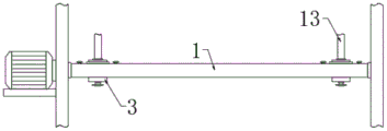
Fig. 1 is a schematic view of the overall structure of the present invention;
FIG. 2 is an enlarged schematic view of the structure of FIG. 1;
FIG. 3 is an enlarged schematic view of the structure of FIG. 1 at B according to the present invention;
fig. 4 is a schematic view of the installation of the utility model on a boring bar.
In the figure: 1. boring and arranging; 2. hollowing out the cavity; 3. a sleeve; 4. an installation mechanism; 5. a placement chamber; 6. a transmission mechanism; 7. a first lead screw; 8. a first threaded barrel; 9. a first connecting plate; 10. a slide bar; 11. mounting a plate; 12. a bolt; 13. a cutter bar; 14. accommodating grooves; 15. a second lead screw; 16. a second threaded barrel; 17. pressing a plate; 18. a limiting block; 19. a first gear; 20. a second gear; 21. a second connecting plate; 22. a limiting rod; 23. a first rotating handle; 24. a second rotating handle; 25. and a limiting plate.
Detailed Description
The technical solutions in the embodiments of the present invention will be described clearly and completely with reference to the accompanying drawings in the embodiments of the present invention, and it is obvious that the described embodiments are only some embodiments of the present invention, not all embodiments. Based on the embodiments in the present invention, all other embodiments obtained by a person skilled in the art without creative work belong to the protection scope of the present invention.
Referring to fig. 1-4, the utility model provides a boring bar device for processing an inner hole clamp spring groove, which comprises a boring bar 1, wherein hollow cavities 2 are respectively arranged at two ends of the boring bar 1, sleeves 3 are respectively arranged inside the hollow cavities 2, two ends of each sleeve 3 pass through the hollow cavities 2, mounting mechanisms 4 are respectively arranged inside the hollow cavities 2 and at two sides of each sleeve 3, placing cavities 5 are respectively arranged inside the boring bar 1 and at two sides of each hollow cavity 2, a transmission mechanism 6 is arranged inside each placing cavity 5, a first screw rod 7 is movably arranged at the bottom end inside each sleeve 3 through a rotating shaft, a first threaded cylinder 8 is arranged at the top end of each first screw rod 7, the top end of each first threaded cylinder 8 passes through each sleeve 3 through a mounting hole, a first connecting plate 9 is arranged outside the bottom end of each first threaded cylinder 8, slide bars 10 are fixedly arranged inside each sleeve 3 and at two sides of each first screw rod 7, one end of each slide bar, the top end of the first threaded cylinder 8 is provided with a mounting plate 11, the outer side of the top of the mounting plate 11 is provided with a bolt 12, and the top of the mounting plate 11 is provided with a cutter bar 13.
The transmission mechanism 6 comprises a first gear 19 and a second gear 20, the first gear 19 is arranged at one end of a rotating shaft where the second screw rod 15 is located on one side inside the placing cavity 5, the second gear 20 is movably arranged at the top end inside the placing cavity 5 through the rotating shaft, the first gear 19 is meshed with the second gear 20, and the transmission mechanism 6 is used for completing the rotation transmission of the second screw rod 15 in the installing mechanism 4.
Second connecting plate 21 is installed in the one end outside of second thread section of thick bamboo 16, and holding tank 14 is inside to be fixed between second lead screw 15 both sides and clamp plate 17 and is provided with gag lever post 22, and the mounting hole is passed through to gag lever post 22's one end, and gag lever post 22 and second connecting plate 21's connection can provide spacing effect for second thread section of thick bamboo 16, avoids second thread section of thick bamboo 16 can't remove along with the rotation of second lead screw 15.
The bottom of the sleeve 3 is provided with a first rotating handle 23 at one end of a rotating shaft where the first screw rod 7 is located, and the first rotating handle 23 can facilitate a worker to rotate the rotating shaft where the first screw rod 7 is located.
The top of the boring bar 1 is provided with a second rotating handle 24 at one end of a rotating shaft where the second gear 20 is located, and the second rotating handle 24 can facilitate a user to rotate the rotating shaft where the second gear 20 is located.
The limiting plate 25 is arranged on the outer side of the top end of the sleeve 3, the limiting plate 25 arranged on the sleeve 3 can limit the movement of the sleeve 3, the sleeve 3 is prevented from directly penetrating the hollow-out cavity 2, and meanwhile the position of the sleeve 3 in the hollow-out cavity 2 can be limited, so that the work of embedding the limiting block 18 into the inner wall of the sleeve 3 in the installation mechanism 4 can be facilitated.
The limiting block 18 is square, and the limiting block 18 with the square shape has a good limiting effect.
The utility model discloses a theory of operation and use flow: the inner part of the sleeve 3 is a main structure of the device for processing the boring bar 1 and the cutter bar 13 in the inner hole clamp spring groove, when the sleeve 3 is installed, the sleeve 3 can be directly inserted into the hollow-out cavity 2, the movement of the sleeve 3 can be limited by the arrangement of the limiting plate 25 on the sleeve 3, the sleeve 3 is prevented from directly passing through the hollow-out cavity 2, meanwhile, the position of the sleeve 3 in the hollow-out cavity 2 can also be limited, after the insertion work is finished, a worker can respectively rotate the second rotating handle 24 to enable the second gear 20 to rotate, so as to drive the first gear 19 meshed with the second rotating handle to rotate, the second screw rod 15 in the accommodating groove 14 can synchronously rotate along with the rotation of the second gear 20, the second threaded barrel 16 installed on the second screw rod 15 drives the pressing plate 17 to approach the sleeve 3 along with the rotation of the second screw rod 15 through the limiting of the limiting rod 22, so that the two pressing plates 17 both move to abut against the sleeve 3 to finish the installation and fixation work of the sleeve, when clamp plate 17 supports sleeve 3, fixture block on the clamp plate 17 can be embedded in the mounting hole that is located on the sleeve 3 lateral wall, the fixture block can be avoided being carried out vertical displacement by the sleeve 3 of installation with sleeve 3's being connected, thereby further improved the steadiness that sleeve 3 was installed, when cutter arbor 13 is used to needs, the accessible rotates first 23 and makes first lead screw 7 rotate, install the first screw section of thick bamboo 8 on first lead screw 7 and remove along with the rotation of first lead screw 7 through slide bar 10 spacing meeting and drive cutter arbor 13 and remove, thereby accomplish the feed or the back feed regulation work to cutter arbor 13.
Although embodiments of the present invention have been shown and described, it will be appreciated by those skilled in the art that changes, modifications, substitutions and alterations can be made in these embodiments without departing from the principles and spirit of the invention, the scope of which is defined in the appended claims and their equivalents.
Claims (8)
1. The utility model provides an inner hole jump ring groove processing boring bar cutter device, includes boring bar (1), its characterized in that: the novel boring bar is characterized in that hollow cavities (2) are formed in two ends of the boring bar (1), sleeves (3) are arranged inside the hollow cavities (2), two ends of each sleeve (3) penetrate through the hollow cavities (2), mounting mechanisms (4) are arranged inside the hollow cavities (2) and on two sides of each sleeve (3), placing cavities (5) are formed in two sides of each hollow cavity (2) inside the boring bar (1), transmission mechanisms (6) are arranged inside the placing cavities (5), first screw rods (7) are movably arranged at the bottom ends inside the sleeves (3) through rotating shafts, first threaded cylinders (8) are mounted at the top ends of the first screw rods (7), the top ends of the first threaded cylinders (8) penetrate through the sleeves (3) through mounting holes, first connecting plates (9) are arranged on the outer sides of the bottom ends of the first threaded cylinders (8), slide rods (10) are fixedly arranged inside the sleeves (3) on two sides of the first screw rods (7), the one end of slide bar (10) all passes first connecting plate (9) through the mounting hole, first thread section of thick bamboo (8) top is provided with mounting panel (11), mounting panel (11) top outside is provided with bolt (12), mounting panel (11) top is provided with cutter arbor (13).
2. The device for machining the boring cutter bar for the inner hole jump ring groove according to claim 1, wherein: installation mechanism (4) are including holding tank (14), second lead screw (15), second screw thread section of thick bamboo (16), clamp plate (17) and stopper (18), holding tank (14) have all been seted up placing chamber (5) one side to the inside both sides of fretwork chamber (2), holding tank (14) are inside to be provided with second lead screw (15) through the pivot activity, second screw thread section of thick bamboo (16) are all installed to the one end of second lead screw (15), second screw thread section of thick bamboo (16) one end is fixed in sleeve (3) one side and is provided with clamp plate (17), both ends evenly are provided with stopper (18) about clamp plate (17) one side, the one end of stopper (18) is passed through the mounting hole for with sleeve (3) inside the lateral wall.
3. The device for machining the boring cutter bar for the inner hole jump ring groove as claimed in claim 2, wherein: the transmission mechanism (6) comprises a first gear (19) and a second gear (20), the first gear (19) is arranged at one end, where the second screw rod (15) is located, of the inner side of the placing cavity (5), the second gear (20) is movably arranged at the top end of the inner side of the placing cavity (5) through a rotating shaft, and the first gear (19) is meshed with the second gear (20).
4. The device for machining the boring cutter bar for the inner hole jump ring groove as claimed in claim 2, wherein: a second connecting plate (21) is installed on the outer side of one end of the second threaded cylinder (16), a limiting rod (22) is fixedly arranged between the two sides of the second screw rod (15) and the pressing plate (17) inside the accommodating groove (14), and one end of the limiting rod (22) penetrates through the second connecting plate (21) through an installing hole.
5. The device for machining the boring cutter bar for the inner hole jump ring groove according to claim 1, wherein: and a first rotating handle (23) is arranged at one end of the rotating shaft at which the first screw rod (7) is arranged at the bottom of the sleeve (3).
6. The device for machining the boring cutter bar for the inner hole jump ring groove as claimed in claim 3, wherein: and a second rotating handle (24) is arranged at one end of the rotating shaft where the second gear (20) is arranged at the top of the boring bar (1).
7. The device for machining the boring cutter bar for the inner hole jump ring groove according to claim 1, wherein: and a limiting plate (25) is arranged on the outer side of the top end of the sleeve (3).
8. The device for machining the boring cutter bar for the inner hole jump ring groove as claimed in claim 2, wherein: the limiting block (18) is square.
Priority Applications (1)
| Application Number | Priority Date | Filing Date | Title |
|---|---|---|---|
| CN202020456676.2U CN212019422U (en) | 2020-04-01 | 2020-04-01 | Boring cutter bar device for machining inner hole clamp spring groove |
Applications Claiming Priority (1)
| Application Number | Priority Date | Filing Date | Title |
|---|---|---|---|
| CN202020456676.2U CN212019422U (en) | 2020-04-01 | 2020-04-01 | Boring cutter bar device for machining inner hole clamp spring groove |
Publications (1)
| Publication Number | Publication Date |
|---|---|
| CN212019422U true CN212019422U (en) | 2020-11-27 |
Family
ID=73489253
Family Applications (1)
| Application Number | Title | Priority Date | Filing Date |
|---|---|---|---|
| CN202020456676.2U Active CN212019422U (en) | 2020-04-01 | 2020-04-01 | Boring cutter bar device for machining inner hole clamp spring groove |
Country Status (1)
| Country | Link |
|---|---|
| CN (1) | CN212019422U (en) |
-
2020
- 2020-04-01 CN CN202020456676.2U patent/CN212019422U/en active Active
Similar Documents
| Publication | Publication Date | Title |
|---|---|---|
| CN114310374A (en) | Stable high-precision numerical control machining center | |
| CN212019422U (en) | Boring cutter bar device for machining inner hole clamp spring groove | |
| CN203076632U (en) | Drilling mechanism of double-station lock cylinder drilling machine | |
| CN207887944U (en) | A kind of milling machine | |
| CN215238009U (en) | Boring feed device of horizontal lathe | |
| CN207139365U (en) | A kind of CNC milling machine positioning and fastening arrangement for being used to process photovoltaic | |
| CN215998756U (en) | Drilling equipment that machine-building used | |
| CN210996866U (en) | Tool bit mechanism of numerical control equipment | |
| CN209811676U (en) | Machine tool power box with installation positioning device | |
| CN115709304A (en) | Telescopic adjusting type T-shaped milling cutter and fixing assembly thereof | |
| CN214212369U (en) | Milling power head convenient to maintain and replace | |
| CN212495484U (en) | Screw hole bidirectional machining device | |
| CN212683113U (en) | Gear drilling and chamfering integrated equipment | |
| CN210046107U (en) | Drill bit connecting structure for tapping drilling machine | |
| CN211102742U (en) | Numerical control cutter convenient to change | |
| CN210209449U (en) | Detachable Z-direction cutter assembly on machine tool | |
| CN220196921U (en) | Quick tool changing device for numerical control milling machine | |
| CN214185286U (en) | Special processing cutter for boring inner circle of hydraulic cylinder | |
| CN220636970U (en) | Round rod type metal piece clamping and rotating device | |
| CN216502542U (en) | TCT hole saw assembly structure | |
| CN214867316U (en) | Lathe tool bit | |
| CN221676498U (en) | Numerical control lathe positioning tool for turning pump cover | |
| CN218694166U (en) | Workpiece drilling device for numerical control lathe | |
| CN218694156U (en) | Radial feed mechanism of conical deep hole boring machine | |
| CN216326753U (en) | Milling machine round tube lining fixture |
Legal Events
| Date | Code | Title | Description |
|---|---|---|---|
| GR01 | Patent grant | ||
| GR01 | Patent grant |