CN114310374A - Stable high-precision numerical control machining center - Google Patents
Stable high-precision numerical control machining center Download PDFInfo
- Publication number
- CN114310374A CN114310374A CN202111594976.2A CN202111594976A CN114310374A CN 114310374 A CN114310374 A CN 114310374A CN 202111594976 A CN202111594976 A CN 202111594976A CN 114310374 A CN114310374 A CN 114310374A
- Authority
- CN
- China
- Prior art keywords
- ring
- rotating
- numerical control
- arc
- machining center
- Prior art date
- Legal status (The legal status is an assumption and is not a legal conclusion. Google has not performed a legal analysis and makes no representation as to the accuracy of the status listed.)
- Withdrawn
Links
- 238000000034 method Methods 0.000 claims description 3
- 238000003491 array Methods 0.000 claims 1
- 238000009434 installation Methods 0.000 abstract 2
- 238000003754 machining Methods 0.000 description 4
- 238000003801 milling Methods 0.000 description 2
- 238000012356 Product development Methods 0.000 description 1
- 230000004075 alteration Effects 0.000 description 1
- 230000009286 beneficial effect Effects 0.000 description 1
- 230000002860 competitive effect Effects 0.000 description 1
- 238000005520 cutting process Methods 0.000 description 1
- 238000005553 drilling Methods 0.000 description 1
- 238000005516 engineering process Methods 0.000 description 1
- 238000001125 extrusion Methods 0.000 description 1
- 238000010030 laminating Methods 0.000 description 1
- 238000012986 modification Methods 0.000 description 1
- 230000004048 modification Effects 0.000 description 1
- 238000010079 rubber tapping Methods 0.000 description 1
- 238000006467 substitution reaction Methods 0.000 description 1
- 238000003466 welding Methods 0.000 description 1
Images

Abstract
The invention discloses a stable high-precision numerical control machining center which comprises an installation seat and a rotating seat, wherein the rotating seat is rotatably installed on the installation seat, a rotating ring is rotatably installed on the rotating seat, an arc-shaped groove is formed in the inner side wall of the rotating ring, a guide rod is arranged in the arc-shaped groove and is inserted into a support plate, the support plate is vertically installed on the rotating seat, a first spring is sleeved at the upper end of the guide rod, a first resisting ring is arranged on the first spring, the resisting ring is installed on the guide rod, a clamping plate is installed at the lower end of the guide rod, the rotating ring is provided with the arc-shaped groove through the rotating ring, and a rack and a gear are arranged.
Description
Technical Field
The invention relates to the technical field of numerical control machining, in particular to a stable high-precision numerical control machining center.
Background
The numerical control machining center is a numerical control machining tool with complete functions. The functions of milling, boring, drilling, tapping, cutting threads and the like are integrated on one device, so that the device has multiple technological means. The machining center is provided with a tool magazine, various tools or checking tools with different quantities are stored in the tool magazine, and the tools or the checking tools are automatically selected and replaced by programs in the machining process. The main difference between the numerical control milling machine and the numerical control boring machine is that. Particularly for workpieces which need to adopt tools and special equipment to ensure the product quality and efficiency. This will save a lot of time and cost for new product development and retrofit, thus making the enterprise have strong competitive power.
In the process of clamping a workpiece by a numerical control machining center, the clamping is troublesome, the workpiece is often clamped unstably, and meanwhile, the clamping part of the workpiece is short, so that the workpiece is deviated in machining.
Therefore, the invention provides a stable high-precision numerical control machining center for solving the problems.
Disclosure of Invention
The invention aims to provide a stable high-precision numerical control machining center to solve the problems in the background technology.
In order to achieve the purpose, the invention provides the following technical scheme: the utility model provides a high-accuracy numerical control machining center of stable form, includes mount pad and rotation seat, rotates the seat and rotates and install on the mount pad, rotates on the rotation seat and installs the rotating ring, and the arc wall has been seted up to the inside wall of rotating ring, is equipped with the guide bar in the arc wall, and the guide bar is pegged graft in the backup pad, and the backup pad is installed perpendicularly on the rotation seat, and spring one has been cup jointed to the upper end of guide bar, and the higher authority of spring one is equipped with the retaining ring, and the retaining ring is installed on the guide bar, and the cardboard is installed to the lower extreme of guide bar.
Preferably, the rotating ring is provided with a rack, the rack is arc-shaped, the rotating ring positioned at the lower part of the rotating ring is lack of teeth, a gear is arranged on the rotating ring, the gear is rotatably arranged on the rotating seat and meshed with the rack, a groove is formed in the surface of the gear, and the groove is hexagonal prism-shaped.
Preferably, the upper end of guide bar is arc, and the arc wall is provided with three groups, even equidistance array.
Preferably, be equipped with the mounting groove below the rotating ring, the mounting groove is seted up on rotating the seat, and the mounting groove is arc, and the one end of mounting groove is pegged graft and is had the dog of dialling, dials the dog and installs on the rotating ring, is equipped with the flexure strip in the mounting groove, and the flexure strip is "S" type, and the flexure strip is kept away from the one end fixed mounting who dials the dog on the lateral wall of mounting groove.
Preferably, the lateral wall symmetry of rotating ring is equipped with the locking subassembly, and the locking subassembly comprises rectangle frame, round pin axle, spring two, spacing ring and tooth piece, and the rectangle frame symmetry is installed on the surface of rotating the seat, and the round pin axle has been pegged graft on the rectangle frame, and the rectangle frame is passed respectively at the both ends of round pin axle, and the tooth piece is installed to the one end that the round pin axle is close to the rotating ring, tooth piece and rack toothing, and the epaxial spring two that has cup jointed of round pin, spring two are arranged in the rectangle frame, and the one end of spring two is equipped with the spacing ring, and the spacing ring is the ring shape, and fixed mounting is epaxial at the round pin.
Preferably, the one end of round pin axle keeping away from the rotating ring rotates and articulates through the round pin axle has the pull ring, and the pull ring is the semi-annular, and the one end of pull ring is equipped with the peg, and the peg is "L" type, and the peg is installed perpendicularly on the surface of rotating the seat.
Preferably, the tip of cardboard is equipped with the extension plate, and the guiding axle is installed to the lateral wall symmetry of extension plate, and the guiding axle is cylindrical structure, and the guiding axle is pegged graft on the cardboard.
Preferably, the middle of the extension plate is rotatably provided with a threaded rod, the threaded part of the threaded rod is arranged on the clamping plate in a threaded manner, and the end part of the threaded rod is welded with a handle rod.
Preferably, cardboard and extension plate all are arc, and the inner wall homogeneous style of cardboard and extension plate is equipped with the antislip strip, and the antislip strip is provided with the multiunit, along the even equidistance array of the arc surface of cardboard and extension plate.
Compared with the prior art, the invention has the beneficial effects that:
1. by arranging the rotating ring, the arc-shaped groove is formed in the rotating ring, and the rack and the gear are arranged, so that when the workpiece clamping device is used, the rotating ring is conveniently driven to rotate by the gear, the arc-shaped groove pushes the guide rod and the clamping plate to be downward, a workpiece is clamped, and the workpiece clamping device is convenient and simple to operate;
2. the extension plate is installed to the tip plug-in type of cardboard, and rotates on the extension plate and install the threaded rod, and when using, through the rotation of threaded rod 12, conveniently control extension plate 10's extension length for can be with more stable of work piece centre gripping.
Drawings
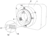
FIG. 1 is a schematic structural view of the present invention;
FIG. 2 is a front view of the structure of the present invention;
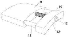
fig. 3 is a partially disassembled view of the present invention.
In the figure: the mounting seat 1, the rotating seat 2, the rotating ring 3, the arc-shaped groove 4, the guide rod 5, the retaining ring 6, the first spring 7, the support plate 8, the clamping plate 9, the extension plate 10, the guide shaft 11, the threaded rod 12, the anti-slip strip 121, the rack 13, the gear 14, the mounting groove 15, the elastic sheet 16, the poking stop block 17, the rectangular frame 18, the pin shaft 19, the second spring 20, the limiting ring 21, the tooth block 22, the pull ring 23 and the hanging rod 24.
Detailed Description
The technical solutions in the embodiments of the present invention will be clearly and completely described below. The embodiments of the present invention, and all other embodiments obtained by a person of ordinary skill in the art without any inventive work, belong to the scope of protection of the present invention.
Referring to fig. 1 to 3, the present invention provides a technical solution: the utility model provides a high-accuracy numerical control machining center of stable form, including mount pad 1 and rotation seat 2, it installs on mount pad 1 to rotate seat 2, it installs swivel becket 3 to rotate on the rotation seat 2, arc 4 has been seted up to swivel becket 3's inside wall, be equipped with guide bar 5 in the arc 4, guide bar 5 is pegged graft in backup pad 8, backup pad 8 is installed perpendicularly on rotating seat 2, spring 7 has been cup jointed to guide bar 5's upper end, the higher authority of spring 7 is equipped with the retaining ring 6, retaining ring 6 is installed on guide bar 5, cardboard 9 is installed to the lower extreme of guide bar 5, when using, anticlockwise rotation through swivel becket 3, just can drive guide bar 5 and cardboard 9 downwards, press from both sides the work piece tightly.
The rack 13 is installed on the rotating ring 3, the rack 13 is arc-shaped, the rotating ring 3 positioned at the lower part of the rotating ring 3 is lack of teeth, the gear 14 is arranged on the rotating ring 3, the gear 14 is installed on the rotating seat 2 in a rotating mode, the gear 14 is meshed with the rack 13, a groove is formed in the surface of the gear 14, the groove is hexagonal prism-shaped, tools can be conveniently inserted into the groove, and when the tool is used, the rotating ring 3 can be driven to rotate anticlockwise through clockwise rotation of the gear 14.
The upper end of guide bar 5 is arc, makes things convenient for arc wall 4 to extrude guide bar 5 downwards, and arc wall 4 is provided with three groups, even equidistance array.
Be equipped with mounting groove 15 below swivel becket 3, mounting groove 15 is seted up on rotating seat 2, mounting groove 15 is arc, the one end of mounting groove 15 is pegged graft and is dialled dog 17, it installs on swivel becket 3 to dial dog 17, be equipped with flexure strip 16 in mounting groove 15, flexure strip 16 is "S" type, flexure strip 16 keeps away from the one end fixed mounting who dials dog 17 on the lateral wall of mounting groove 15, can drive and dial dog 17 extrusion flexure strip 16 using swivel becket 3' S rotation, make flexure strip 16 shrink, when conveniently dismantling the work piece, flexure strip 16 promotes swivel becket 3 and resets.
The side wall of the rotating ring 3 is symmetrically provided with locking components, each locking component is composed of a rectangular frame 18, a pin shaft 19, a second spring 20, a limiting ring 21 and a tooth block 22, the rectangular frames 18 are symmetrically installed on the surface of the rotating seat 2, the pin shafts 19 are inserted into the rectangular frames 18, two ends of each pin shaft 19 penetrate through the rectangular frames 18 respectively, the tooth blocks 22 are installed at one ends, close to the rotating ring 3, of the pin shafts 19, the tooth blocks 22 are meshed with the racks 13, the second springs 20 are sleeved on the pin shafts 19, the second springs 20 are arranged in the rectangular frames 18, the limiting rings 21 are arranged at one ends of the second springs 20, the limiting rings 21 are circular and are fixedly installed on the pin shafts 19, and when the locking component is used, the tooth blocks 22 at the end portions of the pin shafts 19 can be clamped between teeth of the racks 13 through the second springs 20, and the rotating ring 3 is located.
The one end rotation that the pivot axle 19 kept away from the rotating ring 3 has a pull ring 23 through the hinge pin, and pull ring 23 is the half-ring shape, and the one end of pull ring 23 is equipped with peg 24, and peg 24 is "L" type, and peg 24 is installed perpendicularly on the surface of rotating seat 2, when the rotating ring 3 needs the pivoted, just can pull ring 23, hangs pull ring 23 at peg 24, avoids round pin axle 19 and tooth piece 22 to influence the rotation of rotating ring 3.
The tip of cardboard 9 is equipped with extension plate 10, and the guiding axle 11 is installed to the lateral wall symmetry of extension plate 10, and guiding axle 11 is cylindrical structure, and guiding axle 11 pegs graft on cardboard 9.
The threaded rod 12 is installed in the middle of extension plate 10 rotation, and the threaded part screw thread of threaded rod 12 is installed on cardboard 9, and the tip welding of threaded rod 12 has a handle pole, and when using, through the rotation of threaded rod 12, the extension length of convenient control extension plate 10 for can be with more stable of work piece centre gripping.
Cardboard 9 and extension board 10 all are arc, convenient and cylindrical workpiece laminating, and the inner wall homogeneous style of cardboard 9 and extension board 10 is equipped with antislip strip 121, and antislip strip 121 is provided with the multiunit, along the even equidistance array of the arc surface of cardboard 9 and extension board 10.
The working principle is as follows: in the use process, when needing to treat the processing work piece and carry out the clamping, at first place the work piece between cardboard 9, rotate gear 14 clockwise through the instrument after that, gear 14 drives rack 13, make rack 13 drive swivel becket 3 anticlockwise rotation, swivel becket 3's rotation drives guide bar 5 downwards, guide bar 5 drives cardboard 9 downwards, make cardboard 9 carry out the centre gripping with the work piece, after the work piece centre gripping finishes, pull ring 23 from peg 24 down, make round pin axle 19 drive tooth piece 22 insert between the tooth of rack 13, it is spacing to swivel becket 3, start at last and rotate seat 2, it rotates to drive the work piece of treating processing, processing.
Although embodiments of the present invention have been shown and described, it will be appreciated by those skilled in the art that changes, modifications, substitutions and alterations can be made in these embodiments without departing from the principles and spirit of the invention, the scope of which is defined in the appended claims and their equivalents.
Claims (9)
1. A stable high-precision numerical control machining center comprises a mounting base (1) and a rotating base (2);
the rotating seat (2) is rotatably arranged on the mounting seat (1);
the method is characterized in that: a rotating ring (3) is rotatably arranged on the rotating seat (2);
an arc-shaped groove (4) is formed in the inner side wall of the rotating ring (3), and a guide rod (5) is arranged in the arc-shaped groove (4);
the guide rod (5) is inserted on the support plate (8), and the support plate (8) is vertically arranged on the rotating seat (2);
the upper end of the guide rod (5) is sleeved with a first spring (7), a retaining ring (6) is arranged on the first spring (7), the retaining ring (6) is installed on the guide rod (5), and a clamping plate (9) is installed at the lower end of the guide rod (5).
2. The stable high-precision numerical control machining center of claim 1, wherein: the gear rack (13) is mounted on the rotating ring (3), the gear rack (13) is arc-shaped, teeth are not arranged on the rotating ring (3) located on the lower portion of the rotating ring (3), a gear (14) is arranged on the rotating ring (3), the gear (14) is rotatably mounted on the rotating seat (2), the gear (14) is meshed with the gear rack (13), a groove is formed in the surface of the gear (14), and the groove is hexagonal prism-shaped.
3. The stable high-precision numerical control machining center of claim 1, wherein: the upper end of the guide rod (5) is arc-shaped, and three groups of even equidistant arrays are arranged on the arc-shaped grooves (4).
4. The stable high-precision numerical control machining center of claim 1, wherein: be equipped with below swivel becket (3) mounting groove (15), set up on rotating seat (2) mounting groove (15), mounting groove (15) are arc, and the one end of mounting groove (15) is pegged graft and is had group dog (17), dials dog (17) and installs on swivel becket (3), is equipped with flexure strip (16) in mounting groove (15), and flexure strip (16) are "S" type, and flexure strip (16) keep away from the one end fixed mounting who dials dog (17) on the lateral wall of mounting groove (15).
5. The stable high-precision numerical control machining center of claim 1, wherein: the lateral wall symmetry of rotating ring (3) is equipped with the locking subassembly, the locking subassembly is by rectangle frame (18), round pin axle (19), spring two (20), spacing ring (21) and tooth piece (22) are constituteed, rectangle frame (18) symmetry is installed on the surface of rotating seat (2), it has round pin axle (19) to peg graft on rectangle frame (18), rectangle frame (18) is passed respectively at the both ends of round pin axle (19), tooth piece (22) are installed to the one end that round pin axle (19) are close to rotating ring (3), tooth piece (22) and rack (13) meshing, spring two (20) have been cup jointed on round pin axle (19), rectangle frame (18) is arranged in spring two (20), the one end of spring two (20) is equipped with spacing ring (21), spacing ring (21) are the ring shape, and fixed mounting is on round pin axle (19).
6. The stable high-precision numerical control machining center of claim 5, wherein: the one end rotation that the pivot pin (19) kept away from rotating ring (3) has pull ring (23) through the hinge pin joint, and pull ring (23) are the half-ring shape, and the one end of pull ring (23) is equipped with peg (24), and peg (24) are "L" type, and peg (24) are installed perpendicularly on the surface of rotating seat (2).
7. The stable high-precision numerical control machining center of claim 1, wherein: the end of the clamping plate (9) is provided with an extension plate (10), the side wall of the extension plate (10) is symmetrically provided with a guide shaft (11), the guide shaft (11) is of a cylindrical structure, and the guide shaft (11) is inserted into the clamping plate (9).
8. The stable high-precision numerical control machining center of claim 7, wherein: the middle of the extension plate (10) is rotatably provided with a threaded rod (12), the threaded part of the threaded rod (12) is arranged on the clamping plate (9) in a threaded manner, and the end part of the threaded rod (12) is welded with a handle rod.
9. The stable high-precision numerical control machining center of claim 7, wherein: cardboard (9) and extension board (10) all are arc, and the inner wall homogeneous style of cardboard (9) and extension board (10) is equipped with antislip strip (121), and antislip strip (121) are provided with the multiunit, along the even equidistance array of arc surface of cardboard (9) and extension board (10).
Priority Applications (1)
| Application Number | Priority Date | Filing Date | Title |
|---|---|---|---|
| CN202111594976.2A CN114310374A (en) | 2021-12-24 | 2021-12-24 | Stable high-precision numerical control machining center |
Applications Claiming Priority (1)
| Application Number | Priority Date | Filing Date | Title |
|---|---|---|---|
| CN202111594976.2A CN114310374A (en) | 2021-12-24 | 2021-12-24 | Stable high-precision numerical control machining center |
Publications (1)
| Publication Number | Publication Date |
|---|---|
| CN114310374A true CN114310374A (en) | 2022-04-12 |
Family
ID=81013629
Family Applications (1)
| Application Number | Title | Priority Date | Filing Date |
|---|---|---|---|
| CN202111594976.2A Withdrawn CN114310374A (en) | 2021-12-24 | 2021-12-24 | Stable high-precision numerical control machining center |
Country Status (1)
| Country | Link |
|---|---|
| CN (1) | CN114310374A (en) |
Cited By (3)
| Publication number | Priority date | Publication date | Assignee | Title |
|---|---|---|---|---|
| CN115355417A (en) * | 2022-09-09 | 2022-11-18 | 南通大学 | Hydrogen energy reaction unit mounting |
| CN115415616A (en) * | 2022-11-02 | 2022-12-02 | 无锡新大力电机有限公司 | Fine cutting processing device for motor shell |
| CN117139763A (en) * | 2023-08-31 | 2023-12-01 | 武汉安兰斯电气科技有限公司 | Welding equipment and method for copper rotor of motor |
-
2021
- 2021-12-24 CN CN202111594976.2A patent/CN114310374A/en not_active Withdrawn
Cited By (3)
| Publication number | Priority date | Publication date | Assignee | Title |
|---|---|---|---|---|
| CN115355417A (en) * | 2022-09-09 | 2022-11-18 | 南通大学 | Hydrogen energy reaction unit mounting |
| CN115415616A (en) * | 2022-11-02 | 2022-12-02 | 无锡新大力电机有限公司 | Fine cutting processing device for motor shell |
| CN117139763A (en) * | 2023-08-31 | 2023-12-01 | 武汉安兰斯电气科技有限公司 | Welding equipment and method for copper rotor of motor |
Similar Documents
| Publication | Publication Date | Title |
|---|---|---|
| CN114310374A (en) | Stable high-precision numerical control machining center | |
| CN210755413U (en) | Novel outer circle milling device | |
| US4546531A (en) | Set of components for building machine tools | |
| CN211053540U (en) | Adjustable clamp | |
| CN217044635U (en) | Tool setting device of numerical control lathe rotating tool rest | |
| CN212419764U (en) | Efficient intelligence drilling equipment | |
| CN211728780U (en) | Flexible clamping device of polishing machine tool | |
| CN211102742U (en) | Numerical control cutter convenient to change | |
| CN210010687U (en) | Efficient workbench of machining center | |
| CN114310417A (en) | Automatic tool changing device for high-speed five-axis numerical control machine tool | |
| CN220093769U (en) | Cutter arrangement structure of ultra-precise machine tool | |
| CN212265175U (en) | Auxiliary device for machining parts of vertical machining center | |
| CN211331669U (en) | Table tapping machine for processing multi-way blocks | |
| CN218253088U (en) | Semi-automatic clamp for milling machine | |
| CN215315801U (en) | Small bench drill and novel clamping structure | |
| CN211727604U (en) | Small-size parts machining drilling machine | |
| CN212144569U (en) | Automatic drilling machine | |
| CN218983457U (en) | Straight shank thread milling cutter with slotting device | |
| CN215240709U (en) | Cutting table for manufacturing metal products | |
| CN217750467U (en) | Workbench for radial drilling machine | |
| CN220073903U (en) | Turret milling machine | |
| CN113458815B (en) | Hardware drilling clamp for numerical control machine tool | |
| CN218460888U (en) | Cutting tool | |
| CN220372680U (en) | Novel tool apron for machining center | |
| CN215941768U (en) | Machine part electricity processing apparatus for producing |
Legal Events
| Date | Code | Title | Description |
|---|---|---|---|
| PB01 | Publication | ||
| PB01 | Publication | ||
| SE01 | Entry into force of request for substantive examination | ||
| SE01 | Entry into force of request for substantive examination | ||
| WW01 | Invention patent application withdrawn after publication | ||
| WW01 | Invention patent application withdrawn after publication |
Application publication date: 20220412 |