CN212018124U - Grinding device is used in slag processing - Google Patents
Grinding device is used in slag processing Download PDFInfo
- Publication number
- CN212018124U CN212018124U CN202020523948.6U CN202020523948U CN212018124U CN 212018124 U CN212018124 U CN 212018124U CN 202020523948 U CN202020523948 U CN 202020523948U CN 212018124 U CN212018124 U CN 212018124U
- Authority
- CN
- China
- Prior art keywords
- shell
- wall
- screening
- screening groove
- motor
- Prior art date
- Legal status (The legal status is an assumption and is not a legal conclusion. Google has not performed a legal analysis and makes no representation as to the accuracy of the status listed.)
- Expired - Fee Related
Links
- 239000002893 slag Substances 0.000 title claims abstract description 64
- 238000012545 processing Methods 0.000 title claims abstract description 17
- 238000012216 screening Methods 0.000 claims abstract description 97
- 230000007246 mechanism Effects 0.000 claims abstract description 18
- 229910000831 Steel Inorganic materials 0.000 claims description 21
- 239000010959 steel Substances 0.000 claims description 21
- 238000012423 maintenance Methods 0.000 claims description 12
- 230000005540 biological transmission Effects 0.000 claims description 10
- 238000007599 discharging Methods 0.000 claims description 4
- 230000000149 penetrating effect Effects 0.000 claims description 3
- 230000000694 effects Effects 0.000 abstract description 10
- 239000008187 granular material Substances 0.000 abstract description 4
- 230000033001 locomotion Effects 0.000 description 11
- 238000007885 magnetic separation Methods 0.000 description 7
- XEEYBQQBJWHFJM-UHFFFAOYSA-N Iron Chemical compound [Fe] XEEYBQQBJWHFJM-UHFFFAOYSA-N 0.000 description 4
- 230000009467 reduction Effects 0.000 description 4
- 239000000463 material Substances 0.000 description 3
- 238000000034 method Methods 0.000 description 3
- 230000007306 turnover Effects 0.000 description 3
- 239000002699 waste material Substances 0.000 description 3
- 229910000617 Mangalloy Inorganic materials 0.000 description 2
- 230000009286 beneficial effect Effects 0.000 description 2
- 208000002925 dental caries Diseases 0.000 description 2
- 239000002440 industrial waste Substances 0.000 description 2
- 229910052742 iron Inorganic materials 0.000 description 2
- 230000001360 synchronised effect Effects 0.000 description 2
- XLYOFNOQVPJJNP-UHFFFAOYSA-N water Substances O XLYOFNOQVPJJNP-UHFFFAOYSA-N 0.000 description 2
- 229910001018 Cast iron Inorganic materials 0.000 description 1
- 230000004075 alteration Effects 0.000 description 1
- 230000008901 benefit Effects 0.000 description 1
- 230000008878 coupling Effects 0.000 description 1
- 238000010168 coupling process Methods 0.000 description 1
- 238000005859 coupling reaction Methods 0.000 description 1
- 238000005516 engineering process Methods 0.000 description 1
- 238000003912 environmental pollution Methods 0.000 description 1
- 238000000605 extraction Methods 0.000 description 1
- 238000001125 extrusion Methods 0.000 description 1
- 239000004744 fabric Substances 0.000 description 1
- 238000012986 modification Methods 0.000 description 1
- 230000004048 modification Effects 0.000 description 1
- 239000002245 particle Substances 0.000 description 1
- 230000008569 process Effects 0.000 description 1
- 230000008439 repair process Effects 0.000 description 1
- 239000000126 substance Substances 0.000 description 1
- 238000006467 substitution reaction Methods 0.000 description 1
Images

Landscapes
- Crushing And Grinding (AREA)
- Processing Of Solid Wastes (AREA)
Abstract
The utility model discloses a grinder is used in slag processing, the on-line screen storage device comprises a base, the bottom fixedly connected with supporting leg of base both sides, the top fixed mounting of base has first shell and second shell, the inside of first shell is provided with broken mechanism, the inside of second shell is provided with crushing screening mechanism, second shell fixed mounting is at the top of base, first shell fixed mounting is at the top of second shell, first shell communicates with each other with the second shell, broken mechanism includes two at least crushing rollers, the inner wall at first shell is installed through the rotation of first axis of rotation to the crushing roller, the outer wall fixed mounting at the back of first shell has first motor fixing base. Through setting up crushing mechanism and crushing screening mechanism, reached and carried out the effect of accurate breakage again after tentatively breaking the slag, through the convertible crushing and the screening of screening groove to the slag, make the slag smash thoroughly, the granule is even.
Description
Technical Field
The utility model relates to a slag processing technology field specifically is a grinder is used in slag processing.
Background
The steel slag belongs to an industrial waste slag, strictly speaking, the steel slag is an industrial waste, the waste can cause environmental pollution if the waste is not utilized reasonably, the steel slag is easy to react after contacting water and air, and thus, the pollution to water sources and land is serious. Therefore, the steel slag is not required to be stacked in a wet environment for a long time, which not only pollutes the environment, but also wastes resources, and has great value if the steel slag can be timely recycled and utilized.
Including handling the case and setting up in the feeder hopper at handling the case top as chinese patent publication No. CN209663330U, the top of handling the case is provided with the crushing roller group that is used for smashing the slag, the bottom of crushing roller group is provided with the magnetic separation roller, the pivot both ends of magnetic separation roller all rotate with handling the case through the bearing frame and be connected, the one end pivot surface cover of magnetic separation roller is equipped with from the driven pulleys, first gear motor's output transmission is connected with driving pulley, the opening has been seted up at the middle part of handling case one side, the bottom of magnetic separation roller is provided with the stock. The utility model discloses a broken roller set and magnetic separation roller that are equipped with, after carrying out the breakage to the slag, utilize the magnetic separation roller to adsorb iron wherein, recycle and scrape the flitch and scrape the ferruginous substance on magnetic separation roller surface down, separate with other materials in the slag to play better grading effect, and because the meshing of crushing roller set is inseparable, crushing effect is good, can smash into less granule with the slag, the subsequent processing and the utilization of being more convenient for.
However, this device has the following disadvantages: this device smashes the slag through crushing roller set, causes the not thorough of slag crushing, and the granule is inhomogeneous to do not sieve the slag after smashing, thereby lead to follow-up more troublesome to the slag processing.
SUMMERY OF THE UTILITY MODEL
An object of the utility model is to provide a grinder is used in slag processing possesses and carries out convertible screening's advantage to the slag when carrying out accurate smashing to the slag, has solved the slag and has smashed not thoroughly, the inhomogeneous problem of granule.
In order to achieve the above object, the utility model provides a following technical scheme: the utility model provides a grinder is used in slag processing, includes the base, the bottom fixedly connected with supporting leg of base both sides, the top fixed mounting of base has first shell and second shell, the inside of first shell is provided with broken mechanism, the inside of second shell is provided with crushing screening mechanism.
The crushing mechanism comprises at least two crushing rollers, the crushing rollers are rotatably arranged on the inner wall of the first shell through a first rotating shaft, a first motor fixing seat is fixedly arranged on the outer wall behind the first shell, a first motor is fixedly arranged on the top of the first motor fixing seat, an output shaft of the first motor and the first rotating shaft are fixedly connected with one end of the outer wall of the first shell in a penetrating mode, a feeding groove is fixedly arranged on the top of the first shell, a discharging hole is formed in the bottom of the second shell cavity, the discharging hole penetrates through the base, and a conical groove is fixedly arranged on the bottom of the first shell cavity.
Smash screening mechanism includes two at least screening grooves, two the screening groove is first screening groove and second screening groove, the equal fixed mounting in bottom of first screening groove and second screening groove has the toper baffle box, first screening groove and second screening groove rotate the inner wall of installing at the second shell through the hollow shaft, the inner wall of first screening groove and second screening groove rotates installs the second axis of rotation, the outer wall fixed mounting of second axis of rotation has broken blade, the outer wall fixed mounting that the second shell is close to first screening groove has second motor fixing base, the bottom fixed mounting of second motor fixing base has the second motor, one of them the one end that first screening groove was worn out in the second axis of rotation and the output shaft fixed connection of second motor, two second axis of rotation transmission is connected.
Preferably, a first maintenance opening is formed in the outer wall of the front face of the first shell, and a second maintenance opening is formed in the outer wall of the front face of the second shell.
Preferably, the first housing and the second housing are fixedly installed by screws.
Preferably, a third motor fixing seat is fixedly mounted on the outer wall of the other side of the second shell, and a speed reduction motor is fixedly mounted at the top of the third motor fixing seat.
Preferably, gear motor penetrates the one end fixed mounting of second shell inner wall and has the carousel, the outer wall that the axle center was kept away from to the carousel articulates there is the movable rod, the other end of movable rod articulates the bottom of keeping away from second axis of rotation one side in first screening groove.
Preferably, a connecting rod is rotatably connected between the outer wall of the first screening groove far away from one side of the second rotating shaft and the outer wall of the second screening groove far away from one side of the second rotating shaft.
Compared with the prior art, the beneficial effects of the utility model are as follows:
firstly, the utility model discloses a set up first motor and crushing roller, reached and to have tentatively broken into the effect that can the broken little slag of precision with bold slag.
Two, the utility model discloses a set up the second motor, start the second motor, the output shaft of second motor rotates and drives one of them second axis of rotation and rotates, through the gear drive effect, two axis of rotation begin to rotate simultaneously, then two axis of rotation drive crushing blade rotate, have reached and have carried out accurate kibbling effect to the slag after preliminary breakage, make the slag particle size after smashing even.
Three, the utility model discloses a set up gear motor, start gear motor, gear motor's output shaft rotates and drives the carousel and rotate, the carousel rotates and drives the movable rod and rotate and be circular reciprocating motion, then the movable rod drives first screening groove and is reciprocating flip motion along the axle center of hollow shaft, first screening groove passes through the connecting rod and drives the second screening groove and be synchronous reciprocating flip motion simultaneously, reciprocating flip motion is reached through the screening groove and can improve the effect of screening speed, can also overturn the slag of screening tank bottom simultaneously, make broken blade can break the slag of bottom, make the slag smash thoroughly, prevent that bottom slag from blockking up the screen cloth.
Fourthly, the utility model discloses a set up bell jar and toper baffle box, reached the effect that prevents that the slag from spilling out the screening tank.
Drawings
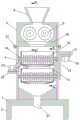
Fig. 1 is a schematic structural view of the front cross-sectional view of the present invention;
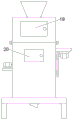
FIG. 2 is a schematic structural view of the front view of the present invention;
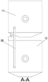
FIG. 3 is a schematic structural view of the cross-sectional view taken along the line A-A of the present invention;
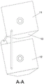
FIG. 4 is a schematic structural view of a cross-sectional view taken along the line A-A after the rotation of the present invention;
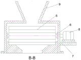
FIG. 5 is a schematic structural view of the cross-sectional view taken along the line B-B of the present invention;
fig. 6 is a partial enlarged view of the turntable and the movable rod of the present invention.
In the figure: 1-base, 2-supporting leg, 3-first shell, 4-second shell, 5-crushing roller, 6-first rotating shaft, 7-first motor fixing seat, 8-first motor, 9-feeding groove, 10-conical groove, 11-first screening groove, 12-second screening groove, 13-conical guide groove, 14-hollow shaft, 15-second rotating shaft, 16-crushing blade, 17-second motor fixing seat, 18-second motor, 19-first maintenance opening, 20-second maintenance opening, 21-screw, 22-third motor fixing seat, 23-speed reducing motor, 24-rotary table, 25-movable rod, 26-connecting rod and 27-discharging opening.
Detailed Description
The technical solutions in the embodiments of the present invention will be described clearly and completely with reference to the accompanying drawings in the embodiments of the present invention, and it is obvious that the described embodiments are only some embodiments of the present invention, not all embodiments. Based on the embodiments in the present invention, all other embodiments obtained by a person skilled in the art without creative work belong to the protection scope of the present invention.
Referring to fig. 1 to 6, the present invention provides a technical solution: the utility model provides a grinder is used in slag processing, includes base 1, and base 1 plays the effect of supporting first shell 3 and second shell 4, and the bottom fixedly connected with supporting leg 2 of base 1 both sides, base 1's top fixed mounting have first shell 3 and second shell 4, and the inside of first shell 3 is provided with crushing mechanism, and the inside of second shell 4 is provided with crushing screening mechanism.
The second shell 4 is fixedly arranged at the top of the base 1, the first shell 3 is fixedly arranged at the top of the second shell 4, the first shell 3 is communicated with the second shell 4, the crushing mechanism comprises at least two crushing rollers 5, the crushing rollers 5 need to be made of materials with larger strength so as to crush the steel slag in an extrusion mode, high manganese steel or high cauterized cast iron can be adopted, the high manganese steel is adopted for the crushing mechanism, the material of the crushing rollers 5 is selected to be beneficial to more rapid and better crushing of the steel slag, meanwhile, a plurality of crushing rollers 5 can be selected to be added according to areas needing crushing, the crushing rollers 5 are rotatably arranged on the inner wall of the first shell 3 through a first rotating shaft 6, a first motor fixing seat 7 is fixedly arranged on the outer wall behind the first shell 3, a first motor 8 is fixedly arranged at the top of the first motor fixing seat 7, and the first motor fixing seat 7 can play a role in fixing and supporting the first motor 8, prevent that first motor 8 from squinting at the operation in-process, shaft coupling fixed connection is passed through with first axis of rotation 6 to the one end that wears out first shell 3 outer wall to the output shaft of first motor 8, first axis of rotation 6 of drive of output shaft of first motor 8 rotates, first axis of rotation 6 drives crushing roller 5 and rotates, carry out the breakage to the slag that falls, the top fixed mounting of first shell 3 has feed chute 9, can pour the slag into first shell 3 through feed chute 9, smash the slag, discharge gate 27 has been seted up to the bottom in the 4 cavitys of second shell, discharge gate 27 runs through base 1, the bottom fixed mounting in the 3 cavitys of first shell has conical chute 10, conical chute 10 can be with the accurate first screening tank 11 that falls into of preliminary kibbling slag, prevent that the slag from spilling the screening tank.
The crushing and screening mechanism comprises at least two screening grooves, the two screening grooves are a first screening groove 11 and a second screening groove 12, the first screening groove 11 and the second screening groove 12 can precisely crush the primarily crushed steel slag and filter the steel slag, the size of the screen holes of the first screening groove 11 is larger than that of the screen holes of the second screening groove 12, and the number of the screening grooves can be determined according to the size of the steel slag to be screened, so that the crushing and screening of the steel slag are more convenient, conical guide grooves 13 are fixedly arranged at the bottoms of the first screening groove 11 and the second screening groove 12, the steel slag can be ensured not to fall outside the screening grooves in the process of falling into the second screening groove 12 from the first screening groove 11 through the conical guide grooves 10, the first screening groove 11 and the second screening groove 12 are rotatably arranged on the inner wall of the second shell 4 through a hollow shaft 14, and a second rotating shaft 15 is rotatably arranged on the inner walls of the first screening groove 11 and the second screening groove 12, the outer wall of the second rotating shaft 15 is fixedly provided with a crushing blade 16, the crushing blade 16 can precisely crush the primarily crushed steel slag until the steel slag can pass through the screening groove, the outer wall of the second shell 4 close to the first screening groove 11 is fixedly provided with a second motor fixing seat 17, the second motor fixing seat 17 can fix a second motor 18, and can also be conveniently detached and maintained, the bottom of the second motor fixing seat 17 is fixedly provided with a second motor 18, one end of the second rotating shaft 15 penetrating through the first screening groove 11 is fixedly connected with an output shaft of the second motor 18, the two second rotating shafts 15 are in transmission connection, the two rotating shafts can be in transmission connection with a toothed belt through a gear, can also be in transmission connection with a belt pulley through a belt, and can also be in transmission connection with a chain through a gear, the example is realized by the gear and the chain, and the example is in transmission connection with the belt through, two transmission shafts wear out the surface of 4 one ends of second shell and do not fixed mounting have two gears, and two gears pass through chain drive and connect, and the output shaft of second motor 18 rotates and drives one of them second axis of rotation 15 and rotate, drives two gear drive simultaneously, drives another second axis of rotation 15 and rotates simultaneously, and two second axis of rotation 15 drive crushing blade 16 and rotate, carry out accurate breakage to the slag after the preliminary breakage that falls, until can pass through the screening groove.
Furthermore, a first maintenance port 19 is formed in the outer wall of the front of the first shell 3, a second maintenance port 20 is formed in the outer wall of the front of the second shell 4, the inner walls of the first shell 3 and the second shell 4 can be inspected and maintained through the first maintenance port 19 and the second maintenance port 20, the first shell 3 and the second shell 4 do not need to be detached, and the device is convenient to maintain.
Furthermore, the first housing 3 and the second housing 4 are fixedly installed by a screw 21, the first housing 3 and the second housing 4 are fixed by the screw 21, and if the first maintenance opening 19 and the second maintenance opening 20 cannot be used for removing the fault, the screw 21 and the nut are directly unscrewed when the first housing 3 and the second housing 4 need to be dismounted, so that the repair is facilitated.
Further, a third motor fixing seat 22 is fixedly mounted on the outer wall of the other side of the second casing 4, a speed reduction motor 23 is fixedly mounted at the top of the third motor fixing seat 22, the third motor fixing seat 22 can fix and support the speed reduction motor 23, and the rotating speed of the speed reduction motor 23 is lower than that of a common motor.
Further, gear motor 23 penetrates the one end fixed mounting of 4 inner walls of second shell has carousel 24, the outer wall that carousel 24 kept away from the axle center articulates there is the movable rod 25, the other end of movable rod 25 articulates the bottom of keeping away from second axis of rotation 15 one side in first screening groove 11, gear motor 23's output shaft rotates and drives carousel 24 and rotate, then carousel 24 drives movable rod 25 and is circular motion, the other end of movable rod 25 drives first screening groove 11 and is reciprocal flip motion along hollow shaft 14, can improve the screening speed of slag, the slag that can also fall in screening tank bottom portion simultaneously overturns, make things convenient for crushing blade 16 to carry out the precision crushing to the slag.
Further, a connecting rod 26 is rotatably connected between the outer wall of the first screening groove 11 far away from the second rotating shaft 15 and the outer wall of the second screening groove 12 far away from the second rotating shaft 15, the first screening groove 11 drives the second screening groove 12 to move through the connecting rod 26 when reciprocating and overturning, and the second screening groove 12 and the first screening groove 11 perform reciprocating and overturning movement in the same direction.
The working principle is as follows: when the grinding device for processing the steel slag is used, a plurality of crushing rollers 5 are selected to be installed according to the area and size to be crushed, then at least two screening grooves are installed according to the size of the crushed steel slag, after the crushing rollers 5 and the screening grooves are selected, a first motor 8 is started, the first motor 8 drives a first rotating shaft 6 to rotate, the first rotating shaft 6 drives the crushing rollers 5 to rotate, then when a second motor 18 is started, an output shaft of the second motor 18 rotates to drive one of second rotating shafts 15 to rotate, through the gear transmission effect, the two rotating shafts start to rotate simultaneously, then the two rotating shafts drive crushing blades 16 to rotate, then a speed reducing motor 23 is started, an output shaft of the speed reducing motor 23 rotates to drive a rotating disc 24 to rotate, the rotating disc 24 rotates to drive a movable rod 25 to rotate to do circular reciprocating motion, then the movable rod 25 drives the first screening groove 11 to do reciprocating turnover motion along the axis of a hollow shaft 14, first screening tank 11 passes through connecting rod 26 and drives second screening tank 12 and be synchronous reciprocal turn-over motion simultaneously, then pour into slag from feed chute 9, the slag falls into first screening tank 11 through conical groove 10 after being tentatively broken by crushing roller 5 and carries out the precision breakage, conical groove 10 can prevent that the slag after tentatively broken can not spill when falling into the screening tank who is reciprocal turn-over motion, smash to fall into second screening tank 12 again through first screening tank 11 and smash once more, can pass through second screening tank 12 until the slag, owing to there is toper baffle box 13, the slag can not spill at the in-process that falls into second screening tank 12 from first screening tank 11, then discharge from discharge gate 27 and collect, conveniently follow-up the iron in the follow-up extraction slag.
Although embodiments of the present invention have been shown and described, it will be appreciated by those skilled in the art that changes, modifications, substitutions and alterations can be made in these embodiments without departing from the principles and spirit of the invention, the scope of which is defined in the appended claims and their equivalents.
Claims (6)
1. The utility model provides a grinder is used in slag processing, includes base (1), the bottom fixedly connected with supporting leg (2) of base (1) both sides, its characterized in that: a first shell (3) and a second shell (4) are fixedly mounted at the top of the base (1), a crushing mechanism is arranged in the first shell (3), and a crushing and screening mechanism is arranged in the second shell (4);
the second shell (4) is fixedly arranged at the top of the base (1), the first shell (3) is fixedly arranged at the top of the second shell (4), the first shell (3) is communicated with the second shell (4), the crushing mechanism comprises at least two crushing rollers (5), the crushing rollers (5) are rotatably arranged on the inner wall of the first shell (3) through a first rotating shaft (6), a first motor fixing seat (7) is fixedly arranged on the outer wall of the rear side of the first shell (3), a first motor (8) is fixedly arranged at the top of the first motor fixing seat (7), an output shaft of the first motor (8) is fixedly connected with one end of the first rotating shaft (6) penetrating through the outer wall of the first shell (3), a feeding groove (9) is fixedly arranged at the top of the first shell (3), and a discharging hole (27) is formed in the bottom in the cavity of the second shell (4), the discharge hole (27) penetrates through the base (1), and a conical groove (10) is fixedly arranged at the bottom in the cavity of the first shell (3);
smash screening mechanism includes two at least screening grooves, two the screening groove is first screening groove (11) and second screening groove (12), the equal fixed mounting in bottom of first screening groove (11) and second screening groove (12) has toper baffle box (13), first screening groove (11) and second screening groove (12) rotate through hollow shaft (14) and install the inner wall in second shell (4), the inner wall of first screening groove (11) and second screening groove (12) rotates and installs second axis of rotation (15), the outer wall fixed mounting of second axis of rotation (15) has broken blade (16), outer wall fixed mounting that second shell (4) are close to first screening groove (11) has second motor fixing base (17), the bottom fixed mounting of second motor fixing base has second motor (18), one of them the one end that first screening groove (11) was worn out in second axis of rotation (15) and the output shaft of second motor (18) are fixed The two second rotating shafts (15) are in transmission connection.
2. The steel slag-processing grinding apparatus according to claim 1, wherein: the outer wall in front of the first shell (3) is provided with a first maintenance opening (19), and the outer wall in front of the second shell (4) is provided with a second maintenance opening (20).
3. The steel slag-processing grinding apparatus according to claim 1, wherein: the first shell (3) and the second shell (4) are fixedly installed through screws (21).
4. The steel slag-processing grinding apparatus according to claim 1, wherein: and a third motor fixing seat (22) is fixedly mounted on the outer wall of the other side of the second shell (4), and a speed reducing motor (23) is fixedly mounted at the top of the third motor fixing seat (22).
5. The steel slag-processing grinding apparatus according to claim 4, wherein: gear motor (23) penetrate the one end fixed mounting of second shell (4) inner wall have carousel (24), the outer wall that axle center was kept away from in carousel (24) articulates there is movable rod (25), the other end of movable rod (25) articulates the bottom of keeping away from second axis of rotation (15) one side in first screening groove (11).
6. The steel slag-processing grinding apparatus according to claim 1, wherein: and a connecting rod (26) is rotatably connected between the outer wall of one side, away from the second rotating shaft (15), of the first screening groove (11) and the outer wall of one side, away from the second rotating shaft (15), of the second screening groove (12).
Priority Applications (1)
| Application Number | Priority Date | Filing Date | Title |
|---|---|---|---|
| CN202020523948.6U CN212018124U (en) | 2020-04-11 | 2020-04-11 | Grinding device is used in slag processing |
Applications Claiming Priority (1)
| Application Number | Priority Date | Filing Date | Title |
|---|---|---|---|
| CN202020523948.6U CN212018124U (en) | 2020-04-11 | 2020-04-11 | Grinding device is used in slag processing |
Publications (1)
| Publication Number | Publication Date |
|---|---|
| CN212018124U true CN212018124U (en) | 2020-11-27 |
Family
ID=73490576
Family Applications (1)
| Application Number | Title | Priority Date | Filing Date |
|---|---|---|---|
| CN202020523948.6U Expired - Fee Related CN212018124U (en) | 2020-04-11 | 2020-04-11 | Grinding device is used in slag processing |
Country Status (1)
| Country | Link |
|---|---|
| CN (1) | CN212018124U (en) |
Cited By (1)
| Publication number | Priority date | Publication date | Assignee | Title |
|---|---|---|---|---|
| CN115007264A (en) * | 2022-07-01 | 2022-09-06 | 淮安市行健再生资源利用有限公司 | Automatic equipment for processing steel slag grinding material |
-
2020
- 2020-04-11 CN CN202020523948.6U patent/CN212018124U/en not_active Expired - Fee Related
Cited By (2)
| Publication number | Priority date | Publication date | Assignee | Title |
|---|---|---|---|---|
| CN115007264A (en) * | 2022-07-01 | 2022-09-06 | 淮安市行健再生资源利用有限公司 | Automatic equipment for processing steel slag grinding material |
| CN115007264B (en) * | 2022-07-01 | 2023-09-22 | 淮安市行健再生资源利用有限公司 | Automatic equipment for processing steel slag grinding materials |
Similar Documents
| Publication | Publication Date | Title |
|---|---|---|
| CN212018124U (en) | Grinding device is used in slag processing | |
| CN115155714A (en) | Dry-type waste circuit board recovery system | |
| CN111632666A (en) | Crushing device for recycling environment-friendly solid waste | |
| CN109501055B (en) | Waste plastic recovery unit is used in production | |
| CN221046155U (en) | Sample grinding device for rice seed processing | |
| CN214107151U (en) | Raw material crushing device for metallurgical equipment | |
| CN219424514U (en) | Be used for waste material processing apparatus | |
| CN216800006U (en) | Useless solid useless broken separation device of danger | |
| CN216654717U (en) | Raw material crushing device for metallurgical equipment | |
| CN214599306U (en) | High-purity quartz sand production device | |
| CN219682787U (en) | Pretreatment crushing device for recycling industrial solid waste | |
| CN110665623A (en) | Movable type crushing and screening equipment screening device | |
| CN110215975A (en) | A kind of glass pulverizer | |
| CN220940936U (en) | Reducing mechanism is used in iron ore detection | |
| CN221085896U (en) | Concrete breaker for building site | |
| CN215429243U (en) | Chemical raw material grinding device for chemical industry | |
| CN213494145U (en) | Crushing and refining device for recycling concrete blocks | |
| CN216173006U (en) | Grinding equipment for ceramic machining | |
| CN217910639U (en) | Sweeps processing apparatus is used in circuit board processing | |
| CN221276236U (en) | Regenerated asphalt raw material adding device | |
| CN221288007U (en) | Garbage recycling device for decoration engineering | |
| CN221714402U (en) | Raw material crushing mechanism for chemical production | |
| CN218365933U (en) | Plastic particle crusher | |
| CN218308171U (en) | Be used for kibbling processingequipment of zeolite | |
| CN221558640U (en) | Mine pulverizer with screening function |
Legal Events
| Date | Code | Title | Description |
|---|---|---|---|
| GR01 | Patent grant | ||
| GR01 | Patent grant | ||
| CF01 | Termination of patent right due to non-payment of annual fee |
Granted publication date: 20201127 |
|
| CF01 | Termination of patent right due to non-payment of annual fee |