CN211985599U - Novel electric thyroid puncture device with negative pressure - Google Patents
Novel electric thyroid puncture device with negative pressure Download PDFInfo
- Publication number
- CN211985599U CN211985599U CN202020087005.3U CN202020087005U CN211985599U CN 211985599 U CN211985599 U CN 211985599U CN 202020087005 U CN202020087005 U CN 202020087005U CN 211985599 U CN211985599 U CN 211985599U
- Authority
- CN
- China
- Prior art keywords
- needle body
- negative pressure
- cap
- handle
- rotating shaft
- Prior art date
- Legal status (The legal status is an assumption and is not a legal conclusion. Google has not performed a legal analysis and makes no representation as to the accuracy of the status listed.)
- Active
Links
Images
Abstract
The utility model discloses an electronic novel thyroid gland piercing depth who takes negative pressure, it includes needle body, negative pressure device, motor and handle, the handle includes the puncture end and controls the end, the handle has the installation cavity, the motor install in the installation cavity, needle body connect in the motor, the needle body stretch out in the puncture end of handle, needle body connect in negative pressure device. The novel electric thyroid puncture device with negative pressure is provided with the puncture needle body capable of electrically rotating, so that the sampling difficulty is greatly reduced.
Description
Technical Field
The utility model relates to the field of medical equipment, concretely relates to novel thyroid gland piercing depth of electronic area negative pressure device.
Background
Clinically, in the process of diagnosing certain thyroid diseases, a puncture needle is often used for performing puncture biopsy on a thyroid to be treated under the guidance of ultrasound, so that a pathological specimen is obtained for diagnosis. At present, puncture biopsy at home and abroad is widely performed by adopting various types of puncture needles or directly holding an injector to enable the puncture needle to enter a tumor through skin, then repeatedly advance and retreat in the tumor for many times, and is assisted with negative pressure suction to obtain puncture objects for cytological analysis. The thyroid puncture biopsy is divided into a coarse needle puncture and a fine needle puncture. The fine needle aspiration biopsy has the advantages of small damage to tissues, less bleeding, safety, rapidness and less infection chance, has higher sensitivity and specificity when being applied to cytological diagnosis, and is widely applied clinically. Researches show that the fine needle aspiration biopsy also has certain disadvantages, for example, for parts to be detected with deep positions or small volumes, the focus is difficult to puncture by the fine needle under the guidance of ultrasonic, the puncture technical requirement on operators is high, the operation of professional pathologists is required, and the obtained materials are difficult to perform histological detection.
Disclosure of Invention
An object of the utility model is to provide an electronic novel thyroid gland piercing depth who takes negative pressure, this electronic novel thyroid gland piercing depth who takes negative pressure have but the electric rotary's puncture needle body, greatly reduced the sample degree of difficulty.
The technical scheme is as follows:
electric novel thyroid gland piercing depth who takes negative pressure, including needle body, negative pressure device, motor and handle, the handle includes the puncture end and controls the end, the handle has the installation cavity, the motor install in the installation cavity, the needle body connect in the motor, the needle body stretch out in the puncture end of handle, the needle body connect in negative pressure device.
The needle body is used for the puncture to cut the tissue, take a sample, negative pressure device is used for helping the needle body suction to acquire the puncture thing, the handle is used for medical personnel to operate and grips, the sample of being convenient for, the motor is used for making needle body electric rotation puncture, this electronic novel thyroid gland piercing depth who takes the negative pressure carries traditional manual the plug-in mode to change into electric power rotation cutting, to some positions darker or small wait to detect the position also can easily take a sample, greatly reduced the sample degree of difficulty, reduced the puncture technical requirement to the operator simultaneously.
The novel electric thyroid puncture device with negative pressure further comprises a battery and a switch, wherein the switch is arranged on the periphery of the handle, the battery is installed in the installation cavity, the battery is electrically connected to the motor, and the switch is electrically connected to the battery. For the novel thyroid puncture device of the handheld electric tape negative pressure of medical personnel carries out the puncture biopsy, this novel thyroid puncture device of electronic tape negative pressure sets up the power into the battery form to realize the wireless operation of the novel thyroid puncture device of electronic tape negative pressure, be provided with the switch in week side of handle simultaneously, be convenient for medical personnel open or close the power in operation process.
The novel thyroid puncture device of negative pressure is taken in the electricity still includes pivot and axle cap, the draw-in groove has been seted up to the one end of axle cap, the other end of axle cap connect in the needle body, the one end of pivot connect in the motor, the other end of pivot through install in the draw-in groove of axle cap install in the needle body. Be connected through the pivot between needle body and the motor, the one end of needle body is provided with the axle cap, inserts the axle cap through the pivot between pivot and the needle body and is connected, and this kind of connected mode is located a straight line, has guaranteed the rotatory stability of needle body to make this novel thyroid gland piercing depth of electronic area negative pressure have detachable needle body, satisfy the user demand of needle body as disposable article.
The novel thyroid gland piercing depth of electric belt negative pressure still includes screw cap and stop device, the pivot includes screw thread section and smooth section, the smooth section of pivot install in the axle cap, the screw thread section of pivot is provided with the screw thread, the shaft hole has been seted up to the screw cap, the screw thread section of pivot pass through threaded connection install in the shaft hole, stop device connects in the screw cap, stop device restriction screw cap is along the degree of freedom of the all side directions of handle. Stop device is used for rotating the rotatory while that drives the needle body at the motor, promote advancing of needle body, the screw cap is installed in the screw thread section of pivot, the pivot is rotatory, drive the screw cap, because the screw cap is restricted by stop device along the degree of freedom of the all side directions of handle, the screw cap can only antedisplacement, promote the needle body and advance, accomplish rotatory puncture action that advances on one side, improve puncture efficiency, avoid puncturing many times, alleviate the burden of doctor and disease, the incidence that needle track tumour was planted that has reduced artifical the interpolation many times.
The limiting device comprises a movable support and a sliding rail, the sliding rail is arranged on the handle, one end of the movable support is movably connected to the sliding rail, a threaded cap is arranged at the other end of the movable support, and the rotating shaft penetrates through the shaft hole. The needle body is driven rotatory in-process by the motor, the pivot begins rotatoryly simultaneously, because the degree of freedom of the all side direction of screw cap edge handle is restricted by stop device, the screw cap antedisplacement, the pivot drives movable support, the puncture motion of movable support cooperation needle body, relative movement on the slide rail, threaded connection has further strengthened the stability of needle body motion, movable support's design not only promotes the antedisplacement of needle body, and avoid the needle body to rock because of being obstructed at the puncture in-process, the stability of needle body has been strengthened, puncture efficiency has been improved, when the screw cap antedisplacement to smooth section, the pivot of smooth section presents idle running state for the screw cap, the pivot no longer drives the screw cap antedisplacement, movable support removes the tip to the slide rail this moment, stop the needle body antedisplacement, avoid the needle body to continue to advance, prevent that the needle body from dro.
The negative pressure device is an injector, the injector comprises a barrel, a piston is installed at one end of the barrel, an injection port is formed in the other end of the barrel, the piston is arranged at the puncture end of the handle, and the injection port is connected to the needle body. The syringe is the simplest negative pressure device, and need not the power consumption, sets up the syringe in the puncture end of handle, and the thing of puncturing is acquireed in the needle body suction of helping through piston motion, simple structure, reasonable in design.
The injection port is connected to the needle body through a hose, one end of the hose is connected to the needle body, and the other end of the hose is detachably mounted to the injection port. The negative pressure device needs to be communicated with the needle body to realize the suction effect, and the injection port is communicated with the needle body through a hose, so that the negative pressure device is simple, feasible and durable.
The other end of the hose is provided with an injection cap, an injection groove is formed in the injection cap, the injection groove is communicated with the hose, and the injection port is connected to the needle body through the injection groove arranged on the injection cap. The hose and the needle body are connected with the injection port in an inserting mode through the injection cap, and the needle body and the injector are disposable articles, so that the needle body and the injector can be conveniently replaced, disassembled and assembled through inserting connection.
The electric novel thyroid puncture device with negative pressure also comprises a movable bracket and a slide rail, the slide rail is arranged on the handle, the slide rail is arranged along the length direction of the rotating shaft, the rotating shaft comprises a threaded section and a smooth section, the threaded section of the rotating shaft is provided with threads, the smooth section of the rotating shaft is arranged on the shaft cap, the negative pressure device is an injector, the injector comprises a cylinder body, a piston is arranged at one end of the cylinder body, an injection port is arranged at the other end of the cylinder body, the piston is arranged at the puncture end of the handle, the injection port is connected with the needle body, one end of the movable bracket is movably connected with the slide rail, the other end of the movable bracket is fixed on the barrel body, the movable support is provided with a threaded cap, the threaded cap is provided with a shaft hole, and the threaded section of the rotating shaft is installed in the shaft hole through threaded connection. The screw cap is used for driving the needle body to rotate when the motor rotates and the needle body is driven to advance, the screw cap is arranged on the screw thread section of the rotating shaft, the rotating shaft rotates and drives the screw cap, the screw cap can only move forwards to push the needle body to advance as the degree of freedom of the screw cap along the circumferential direction of the handle is limited by the movable support, the puncture action of rotating and advancing at the same time is completed, the puncture efficiency is improved, multiple times of puncture is avoided, the burden of doctors and patients is relieved, the incidence rate of needle path tumor planting caused by multiple times of manual lifting and inserting is reduced, in addition, the barrel body of the syringe is pulled to move forwards relative to the piston while the needle body is pushed to move forwards, the syringe is in a negative pressure state, the needle body is in a negative pressure state, the puncture object is sucked, when the screw cap moves forwards to a smooth section, the rotating shaft, at the moment, the movable support moves to the end part of the sliding rail, and the needle body stops moving forwards, so that the needle body is prevented from continuing to move forwards and falling off.
The movable support comprises a first rod and a second rod, the first rod is parallel to the rotating shaft, one end of the first rod is movably connected with the sliding rail, the other end of the first rod is perpendicularly connected with the second rod, a threaded cap is arranged on the second rod, and the second rod is fixed on the barrel. The sliding rail is arranged along the length direction of the rotating shaft, the first rod is arranged in parallel with the rotating shaft, and the second rod is arranged perpendicular to the first rod.
It should be noted that:
the foregoing "first and second" are merely used for distinguishing between names and do not denote any particular quantity or order.
Drawings
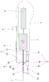
Fig. 1 is a schematic structural view of the novel electric thyroid puncturing device with negative pressure according to the embodiment of the present invention.
Description of reference numerals:
1. a needle body; 10. a shaft cap; 2. an injector; 20. a barrel; 21. a piston; 22. an injection port; 23. a hose; 24. an injection cap; 3. a motor; 4. a handle; 5. a battery; 6. a switch; 7. a rotating shaft; 71. a threaded segment; 72. a smooth section; 8. a movable support; 81. a first lever; 82. a second lever; 9. a slide rail; 90. and (4) a threaded cap.
Detailed Description
The following describes embodiments of the present invention in detail.
As shown in fig. 1, the embodiment discloses a novel electric thyroid puncturing device with negative pressure, which comprises a needle body 1, an injector 2, a motor 3, a handle 4, a battery 5, a switch 6, a rotating shaft 7, a movable support 8 and a sliding rail 9.
Handle 4 includes the puncture end and controls the end, and handle 4 has the installation cavity, and motor 3 and battery 5 install in the installation cavity, and needle body 1 stretches out in the puncture end of handle 4, and needle body 1 connects in motor 3, and needle body 1 connects in syringe 2, and switch 6 sets up in the week side of handle 4, and battery 5 electricity is connected in motor 3, and switch 6 electricity is connected in battery 5. The needle body 1 is used for puncturing and cutting tissues and sampling; the injector 2 is used for helping the needle body 1 to suck and obtain a puncture object; the handle 4 is used for medical staff to operate and hold, and is convenient for sampling; the motor 3 is used for electrically rotating the needle body 1 to puncture; in order to facilitate medical personnel to carry out puncture biopsy by holding the electric negative-pressure thyroid puncture device, a power supply of the electric negative-pressure thyroid puncture device is set to be in a battery 5 form so as to realize wireless operation of the electric negative-pressure thyroid puncture device; meanwhile, a switch 6 is arranged on the periphery of the handle 4, so that medical personnel can conveniently turn on or turn off the power supply in the operation process.
The syringe 2 comprises a barrel 20 and a piston 21, the piston 21 is installed at one end of the barrel 20, an injection port 22 is formed in the other end of the barrel 20, the piston 21 is arranged at the puncture end of the handle 4, the injection port 22 is connected to the needle body 1 through a hose 23, one end of the hose 23 is connected to the needle body 1, an injection cap 24 is arranged at the other end of the hose 23, an injection groove is formed in the injection cap 24 and communicated with the hose 23, and the injection port 22 is connected to the needle body 1 through the injection groove installed in the injection cap 24. The injector 2 is the simplest negative pressure device, power is not needed, the injector 2 is arranged at the puncture end of the handle 4, the movement of the piston 21 helps the needle body 1 to suck and obtain a puncture object, and the injector is simple in structure and reasonable in design; the injector 2 needs to be communicated with the needle body 1 to realize the suction effect, and the injection port 22 is communicated with the needle body 1 through the hose 23, so that the injector is simple, feasible and durable; the hose 23 and the needle body 1 are inserted and connected with the injection port 22 through the injection cap 24, and the needle body 1 and the injector 2 are disposable articles, so that the needle body 1 and the injector 2 can be conveniently replaced and disassembled due to the insertion and connection.
One end that needle body 1 and motor 3 are connected is provided with axle cap 10, the draw-in groove has been seted up to axle cap 10, the one end of pivot 7 is connected in motor 3, the other end of pivot 7 is installed in needle body 1 through the draw-in groove of installing in axle cap 10, be connected through pivot 7 between needle body 1 and the motor 3, the one end of needle body 1 is provided with axle cap 10, insert axle cap 10 through pivot 7 between pivot 7 and the needle body 1 and be connected, this kind of connected mode is located a straight line, the stability of needle body 1 rotation has been guaranteed, and make this novel thyroid gland puncture device of electronic area negative pressure have detachable needle body 1, satisfy the user demand of needle body 1 as disposable articles for use.
In the needle body 1 is driven rotatory in-process by motor 3, pivot 7 begins to rotate simultaneously, because slide rail 9 sets up along the length direction of pivot 7, and first pole 81 sets up in parallel with pivot 7, second pole 82 sets up perpendicular to first pole 81, moreover, the steam generator is simple in structure, make screw cap 90 along the week side direction's of handle 4 degree of freedom by movable support 8 restriction, thereby reach the effect that screw cap 90 moved forward when pivot 7 is rotatory, screw cap 90 can only move forward, promote needle body 1 and advance, accomplish the puncture action of rotating while advancing, improve puncture efficiency, avoid puncture many times, alleviate the burden of doctor and disease, the incidence that needle track tumour was planted that has been brought to many times manual work is carried and is inserted has been reduced.
When the needle body 1 is pushed to move forwards, the barrel 20 of the syringe 2 is pulled to move forwards relative to the piston 21, the syringe 2 is in a negative pressure state, the needle body 1 is in a negative pressure state, and the puncture object is sucked.
When the threaded cap 90 moves forward to the smooth section 72, the rotating shaft 7 of the smooth section 72 is in an idle state relative to the threaded cap 90, the rotating shaft 7 no longer drives the threaded cap 90 to move forward, the movable support 8 moves to the end part of the sliding rail 9 at the moment, the needle body 1 stops moving forward, the needle body 1 is prevented from continuing to move forward, and the needle body 1 is prevented from falling off.
Because the degree of freedom of screw cap 90 along the week side direction of handle 4 is restricted by stop device, screw cap 90 antedisplacement, pivot 7 drives movable support 8, and movable support 8 cooperates the puncture motion of needle body 1, relative movement on slide rail 9, and threaded connection has further strengthened the stability of needle body 1 motion, and movable support 8's design not only promotes the antedisplacement of needle body 1 to avoid needle body 1 to rock because of being obstructed at the puncture in-process.
This novel thyroid gland piercing depth of electronic area negative pressure has the detachable puncture needle body that can electric rotation, and can wireless operation, the first puncture needle has carried out great improvement on the morphological structure, carry traditional manual the plug-in mode and change into the rotatory cutting of electric power, also can easily sample to some positions of waiting to detect that the position is darker or small, greatly reduced the sample degree of difficulty, the puncture technical requirement to the operator has been reduced simultaneously, and the satisfaction rate that the tissue was drawn materials is increased substantially, mainly including increasing the cell sample volume, and then improve diagnostic rate of accuracy, avoid the negative pressure suction to bring the sample quality that contains blood sample influence, improve the effective rate of pathology puncture biopsy.
The above are only specific embodiments of the present invention, and the protection scope of the present invention is not limited thereby; any replacement and improvement made on the basis of not violating the conception of the utility model belong to the protection scope of the utility model.
Claims (10)
1. Electric novel thyroid gland piercing depth who takes negative pressure, a serial communication port, including needle body, negative pressure device, motor and handle, the handle includes the puncture end and controls the end, the handle has the installation cavity, the motor install in the installation cavity, the needle body connect in the motor, the needle body stretch out in the puncture end of handle, the needle body connect in negative pressure device.
2. The electric novel thyroid puncturing device with negative pressure as claimed in claim 1, further comprising a battery and a switch, wherein the switch is disposed on the periphery of the handle, the battery is mounted in the mounting cavity, the battery is electrically connected to the motor, and the switch is electrically connected to the battery.
3. The electric novel thyroid puncturing device with negative pressure according to claim 1, further comprising a rotating shaft and a shaft cap, wherein one end of the shaft cap is provided with a clamping groove, the other end of the shaft cap is connected to the needle body, one end of the rotating shaft is connected to the motor, and the other end of the rotating shaft is mounted on the needle body through the clamping groove mounted on the shaft cap.
4. The electric novel thyroid puncturing device with negative pressure as claimed in claim 3, further comprising a threaded cap and a limiting device, wherein the rotating shaft comprises a threaded section and a smooth section, the smooth section of the rotating shaft is mounted on the shaft cap, the threaded section of the rotating shaft is provided with threads, the threaded cap is provided with a shaft hole, the threaded section of the rotating shaft is mounted on the shaft hole through threaded connection, the limiting device is connected to the threaded cap, and the limiting device limits the degree of freedom of the threaded cap along the circumferential direction of the handle.
5. The electric novel thyroid puncturing device with negative pressure as claimed in claim 4, wherein the limiting device comprises a movable bracket and a slide rail, the slide rail is disposed on the handle, one end of the movable bracket is movably connected to the slide rail, the other end of the movable bracket is provided with a threaded cap, and the rotating shaft passes through the shaft hole.
6. The novel electric thyroid puncturing device with negative pressure according to any one of claims 1 to 5, wherein the negative pressure device is a syringe, the syringe comprises a barrel, a piston is mounted at one end of the barrel, an injection port is arranged at the other end of the barrel, the piston is arranged at the puncturing end of the handle, and the injection port is connected to the needle body.
7. The novel electric negative pressure thyroid puncturing device as claimed in claim 6, wherein the injection port is connected to the needle body through a flexible tube, one end of the flexible tube is connected to the needle body, and the other end of the flexible tube is detachably mounted to the injection port.
8. The electric vacuum thyroid puncturing device as claimed in claim 7, wherein an injection cap is provided at the other end of the flexible tube, an injection groove is provided in the injection cap, the injection groove is in communication with the flexible tube, and the injection port is connected to the needle body through the injection groove mounted on the injection cap.
9. The electric novel thyroid puncturing device with negative pressure as claimed in claim 3, further comprising a movable bracket and a sliding rail, the slide rail is arranged on the handle, the slide rail is arranged along the length direction of the rotating shaft, the rotating shaft comprises a threaded section and a smooth section, the thread section of the rotating shaft is provided with threads, the smooth section of the rotating shaft is arranged on the shaft cap, the negative pressure device is an injector, the injector comprises a cylinder body, one end of the cylinder body is provided with a piston, the other end of the cylinder body is provided with an injection port, the piston is arranged at the puncture end of the handle, the injection port is connected with the needle body, one end of the movable bracket is movably connected with the slide rail, the other end of the movable support is fixed on the cylinder body, the movable support is provided with a threaded cap, the threaded cap is provided with a shaft hole, and the threaded section of the rotating shaft is installed in the shaft hole through threaded connection.
10. The electric novel thyroid puncturing device with negative pressure as claimed in claim 9, wherein the movable support comprises a first rod and a second rod, the first rod is parallel to the rotating shaft, one end of the first rod is movably connected to the sliding rail, the other end of the first rod is vertically connected to the second rod, a threaded cap is arranged on the second rod, and the second rod is fixed to the barrel.
Priority Applications (1)
| Application Number | Priority Date | Filing Date | Title |
|---|---|---|---|
| CN202020087005.3U CN211985599U (en) | 2020-01-14 | 2020-01-14 | Novel electric thyroid puncture device with negative pressure |
Applications Claiming Priority (1)
| Application Number | Priority Date | Filing Date | Title |
|---|---|---|---|
| CN202020087005.3U CN211985599U (en) | 2020-01-14 | 2020-01-14 | Novel electric thyroid puncture device with negative pressure |
Publications (1)
| Publication Number | Publication Date |
|---|---|
| CN211985599U true CN211985599U (en) | 2020-11-24 |
Family
ID=73426246
Family Applications (1)
| Application Number | Title | Priority Date | Filing Date |
|---|---|---|---|
| CN202020087005.3U Active CN211985599U (en) | 2020-01-14 | 2020-01-14 | Novel electric thyroid puncture device with negative pressure |
Country Status (1)
| Country | Link |
|---|---|
| CN (1) | CN211985599U (en) |
-
2020
- 2020-01-14 CN CN202020087005.3U patent/CN211985599U/en active Active
Similar Documents
| Publication | Publication Date | Title |
|---|---|---|
| CA2538406C (en) | Biopsy device with variable side aperture | |
| US7481775B2 (en) | Biopsy device incorporating an adjustable probe sleeve | |
| KR101275917B1 (en) | Dual purpose pen type device for ultrasound guided fine needle aspiration and core needle biopsy | |
| CN108113714A (en) | A kind of blood internal medicine bone marrow aspiration draw-out device | |
| CN109758188A (en) | A kind of clinical medicine biopsy sampling collection device | |
| CN211985599U (en) | Novel electric thyroid puncture device with negative pressure | |
| CN209678563U (en) | A kind of pathology department's bone marrow aspiration biopsy needle | |
| CN108433752B (en) | Stomach cancer holostrome sample sampler | |
| CN214017633U (en) | Sampler for medical oncology puncture biopsy | |
| CN212755735U (en) | Puncture outfit for cytopathology examination | |
| CN210811208U (en) | Clinical puncture sampler for oncology department | |
| CN211325078U (en) | Disposable automatic blood taking needle with positioning function | |
| CN201394032Y (en) | Multi-hole ring rotary type myeloid biopsy needle | |
| CN208223846U (en) | A kind of oncology laboratory sampling device | |
| CN209285583U (en) | A kind of blood internal medicine device for collecting marrow | |
| CN105615928A (en) | Syringe needle | |
| CN110236567B (en) | Blood sampling device | |
| CN220588331U (en) | Tumor puncturing device | |
| CN220676041U (en) | Mammary tumor puncture biopsy device | |
| CN215129147U (en) | Gynecological tumor sample tissue sampling device | |
| CN219183866U (en) | Adjustable lymph node puncture biopsy needle | |
| CN107898480A (en) | A kind of Direct Microsurgical sexual system for bone tissue aspiration biopsy | |
| CN212382659U (en) | Bone aspiration biopsy needle structure | |
| CN212261374U (en) | Novel animal doctor uses vein hemostix | |
| CN214907372U (en) | Tissue sampling device |
Legal Events
| Date | Code | Title | Description |
|---|---|---|---|
| GR01 | Patent grant | ||
| GR01 | Patent grant |