CN211963735U - Anesthesia department is with anesthesia waste gas pump drainage device - Google Patents
Anesthesia department is with anesthesia waste gas pump drainage device Download PDFInfo
- Publication number
- CN211963735U CN211963735U CN202020151243.6U CN202020151243U CN211963735U CN 211963735 U CN211963735 U CN 211963735U CN 202020151243 U CN202020151243 U CN 202020151243U CN 211963735 U CN211963735 U CN 211963735U
- Authority
- CN
- China
- Prior art keywords
- wall
- collecting box
- anesthesia
- fixed
- waste gas
- Prior art date
- Legal status (The legal status is an assumption and is not a legal conclusion. Google has not performed a legal analysis and makes no representation as to the accuracy of the status listed.)
- Expired - Fee Related
Links
Images


Abstract
The utility model discloses an anesthesia administrative or technical offices are with anesthesia waste gas extraction device, the collecting box comprises a collecting box, fixedly connected with backup pad on one side outer wall of collecting box has the air pressure pump through the bolt fastening on the top outer wall of backup pad, and it has the intake pipe to peg graft on the air inlet inner wall of air pressure pump, and it has the outlet duct to peg graft on the gas outlet inner wall of air pressure pump, it has the rectangle mouth to open on the top outer wall of collecting box, is equipped with on one side inner wall of rectangle mouth and sprays the mechanism, there are a plurality of cassettes through the bolt fastening on one side inner wall of collecting box, and the joint has the active carbon filter screen on one side outer wall of cassette, there is sterilamp through the bolt fastening on one side inner wall of collecting box. The utility model discloses inhale the collecting box with anesthesia waste gas by the anesthesia room to adsorb through absorbent, the catalyst on active carbon filter screen surface, detach partial compound, impurity and particulate matter, and open sterilamp and disinfect.
Description
Technical Field
The utility model relates to a waste gas extraction device technical field especially relates to an anesthesia department is with anesthesia waste gas extraction device.
Background
Anesthesia means that a patient loses the sense of pain wholly or locally temporarily by using a medicine or other methods to achieve the purpose of painless operation treatment, anesthesiology is a science for eliminating the operation pain of the patient and ensuring the safety of the patient by applying basic theories, clinical knowledge and technologies related to anesthesia and creating good conditions for the operation, an anesthesia department usually generates anesthesia waste gas, and the anesthesia waste gas needs to be removed by an anesthesia waste gas extraction device.
At present, most of the existing anesthesia waste gas extraction devices for anesthesia departments in the market have the following defects in the using process: the anesthesia waste gas just discharges without handling, and the direct discharge of anesthesia waste gas can cause the influence to external environment to the external world, to sum up, most anesthesia departments that have now can not agree with actual need well with anesthesia waste gas extraction device.
SUMMERY OF THE UTILITY MODEL
The utility model aims at solving the defects existing in the prior art and providing an anesthesia waste gas extraction device for an anesthesia department.
In order to achieve the above purpose, the utility model adopts the following technical scheme:
the utility model provides an anesthesia administrative or technical offices are with anesthesia waste gas pump-out device, includes the collecting box, fixedly connected with backup pad on the outer wall of one side of collecting box has the pneumatic pump through the bolt fastening on the top outer wall of backup pad, and it has the intake pipe to peg graft on the air inlet inner wall of pneumatic pump, and it has the outlet duct to peg graft on the gas outlet inner wall of pneumatic pump, it has the rectangle mouth to open on the top outer wall of collecting box, is equipped with on the one side inner wall of rectangle mouth and sprays the mechanism, there are a plurality of cassettes through the bolt fastening on the inner wall of one side of collecting box, the joint has the active carbon filter screen on the outer wall of one side of cassette, there is sterilamp through the bolt fastening on.
Further, the spraying mechanism comprises a water tank, the water tank is fixed on the inner wall of one side of the rectangular opening through bolts, a water pump is fixed on the inner wall of the bottom of the water tank through bolts, a water inlet pipe is inserted into the inner wall of a water inlet of the water pump, a water outlet pipe is inserted into the inner wall of a water outlet of the water pump, one end of the water outlet pipe is located inside the collecting box, and a shower head is screwed to one end of the water outlet pipe.
Furthermore, the shower head is positioned close to the air outlet pipe.
Further, exhaust mechanism includes fixed plate and fan, and the fixed plate passes through the bolt fastening on one side inner wall of collecting box, and the fan passes through the bolt fastening on the top outer wall of fixed plate, and the import of fan is pegged graft and is had the wind scoop that the slope was put, and the export of fan is pegged graft and is had the blast pipe, and the one end of blast pipe is located the outside of collecting box.
Furthermore, the circumference inner wall of blast pipe goes up the joint and has the steel wire filter screen.
Furthermore, a position, close to the bottom, of the outer wall of one side of the collecting box is connected with a liquid discharge pipe in an inserting mode, an electromagnetic valve is fixed on the outer wall of one side of the liquid discharge pipe through a bolt, and an installation door is hinged to the outer wall of one side of the collecting box.
Further, still include waterproof heater, waterproof heater passes through the bolt fastening on the bottom inner wall of collecting box.
The utility model has the advantages that:
1. through the pneumatic pump, cassette, active carbon filter screen and sterilamp that set up, inhale the collecting box with anesthesia waste gas by the anesthesia room to adsorb through adsorbent, the catalyst on active carbon filter screen surface, detach some compounds, impurity and particulate matter, and open sterilamp and disinfect.
2. Through water pump, gondola water faucet and the fan that sets up, utilize the water pump to absorb water the back and spray through the gondola water faucet and go out, spray anesthetic gas, dissolve partial gas in aquatic, then discharge along with the waste liquid, the gas after the processing is discharged by the fan, and the steel wire filter screen in the exhaust pipe prevents that external foreign matter from getting into.
3. Through the waterproof heater who sets up, can heat the disinfection to waste water to make discharged waste water accord with the standard, the device convenient to use satisfies people's demand.
Drawings
Fig. 1 is a schematic sectional view of an anesthetic waste gas extraction device 1 for an anesthetic department according to the present invention.
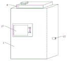
Fig. 2 is a schematic perspective view of an anesthetic waste gas extraction device 1 for an anesthesia department according to an embodiment of the present invention.
Fig. 3 is a schematic sectional view of the anesthetic waste gas exhausting device in the embodiment 2 of the present invention.
In the figure: 1-collection box, 2-air inlet pipe, 3-pneumatic pump, 4-water pump, 5-shower head, 6-clamping seat, 7-active carbon filter screen, 8-wind scoop, 9-water tank, 10-ultraviolet germicidal lamp, 11-steel wire filter screen, 12-exhaust pipe, 13-blower, 14-fixing plate, 15-liquid discharge pipe, 16-electromagnetic valve, 17-installation door and 18-waterproof heater.
Detailed Description
The technical solutions in the embodiments of the present invention will be described clearly and completely with reference to the accompanying drawings in the embodiments of the present invention, and it is obvious that the described embodiments are only some embodiments of the present invention, not all embodiments.
In the description of this patent, it is to be understood that the terms "center", "upper", "lower", "front", "rear", "left", "right", "vertical", "horizontal", "top", "bottom", "inner", "outer", etc. indicate orientations or positional relationships based on those shown in the drawings, and are used for convenience of description and simplicity of description, but do not indicate or imply that the referenced device or component must have a particular orientation, be constructed and operated in a particular orientation, and therefore are not to be considered limiting of the patent, and the terms "mounted", "disposed", "connected", "fixed", "screwed" and the like are to be construed broadly and may be fixedly connected, detachably connected, or integrally formed, for example; can be mechanically or electrically connected; they may be directly connected or indirectly connected through an intermediate, or they may be connected internally or in an interactive relationship with each other, and unless otherwise specifically limited, the specific meaning of the above terms in this patent will be understood by those skilled in the art according to the specific circumstances.
Example 1
Referring to fig. 1-2, an anesthesia waste gas extraction device for anesthesia departments comprises a collection box 1, a support plate is fixedly connected to the outer wall of one side of the collection box 1, a pneumatic pump 3 is fixed to the outer wall of the top of the support plate through bolts, an air inlet pipe 2 is inserted into the inner wall of an air inlet of the pneumatic pump 3, an air outlet pipe is inserted into the inner wall of an air outlet of the pneumatic pump 3, a rectangular opening is formed in the outer wall of the top of the collection box 1, a spraying mechanism is arranged on the inner wall of one side of the rectangular opening, a plurality of clamping seats 6 are fixed to the inner wall of one side of the collection box 1 through bolts, an active carbon filter screen 7 is clamped to the outer wall of one side of the clamping seats 6, an ultraviolet sterilization lamp 10 is fixed to the inner wall of one side of the collection box 1 through bolts, the pneumatic pump 3 is started to suck anesthesia waste, the surface of the active carbon filter screen 7 is provided with an adsorbent and a catalyst, so that the anesthetic waste gas can be conveniently adsorbed, partial compounds, impurities, inhalable particles and the like can be removed, the ultraviolet germicidal lamp 10 sterilizes, and the inner wall of one side of the collecting box 1 is provided with an exhaust mechanism.
In the utility model, the spraying mechanism comprises a water tank 9, the water tank 9 is fixed on one side inner wall of a rectangular opening through bolts, a water pump 4 is fixed on the bottom inner wall of the water tank 9 through bolts, a water inlet pipe is inserted on the inner wall of a water inlet of the water pump 4, a water outlet pipe is inserted on the inner wall of a water outlet of the water pump 4, one end of the water outlet pipe is positioned inside a collecting box 1, a shower head 5 is screwed at one end of the water outlet pipe, the shower head 5 is positioned at a position close to an air outlet pipe, the air exhaust mechanism comprises a fixed plate 14 and a fan 13, the fixed plate 14 is fixed on one side inner wall of the collecting box 1 through bolts, the fan 13 is fixed on the top outer wall of the fixed plate 14 through bolts, an air funnel 8 which is obliquely arranged is inserted at the inlet of the fan 13, an exhaust pipe, the position that one side outer wall of collecting box 1 is close to the bottom is pegged graft and is had fluid-discharge tube 15, there is solenoid valve 16 through the bolt fastening on one side outer wall of fluid-discharge tube 15, it has installation door 17 to articulate on one side outer wall of collecting box 1, start water pump 4, carry the clear water to gondola water faucet 5 departments and spray waste gas, dissolve waste gas into aquatic, collect inside collecting box 1, purify the back, start fan 13, fan 13 is discharged gas by blast pipe 12 through wind fill 8, steel wire filter screen 11 can prevent that the foreign matter from getting into, then open 15 exhaust waste water of fluid-discharge tube.
The working principle is as follows: during the use, with equipment external power supply, start in pneumatic pump 3 inhales collecting box 1 with the anesthesia room production anesthesia waste gas, then open sterilamp 10 and disinfect, and adsorb through activated carbon filter 7, activated carbon filter 7 surface is equipped with adsorbent and catalyst, conveniently adsorb anesthesia waste gas, detach partial compound, impurity and inhalable particle etc, sterilamp 10 disinfects, then start water pump 4, carry 5 departments of gondola water faucet to the clear water and spray waste gas, dissolve waste gas in the aquatic, collect inside collecting box 1, purify the back, start fan 13, fan 13 discharges gas by blast pipe 12 through wind scoop 8, steel wire filter 11 can prevent the foreign matter entering, then open fluid-discharge tube 15 exhaust waste water.
Example 2
Referring to fig. 3, the anesthetic waste gas pumping device for an anesthesia department, compared to embodiment 1, further includes a waterproof heater 18, and the waterproof heater 18 is fixed on the bottom inner wall of the collection box 1 through a bolt.
The working principle is as follows: when in use, the waterproof heater 18 can be started to heat the wastewater, sterilize the wastewater at high temperature and then discharge the wastewater.
The above, only be the concrete implementation of the preferred embodiment of the present invention, but the protection scope of the present invention is not limited thereto, and any person skilled in the art is in the technical scope of the present invention, according to the technical solution of the present invention and the utility model, the concept of which is equivalent to replace or change, should be covered within the protection scope of the present invention.
Claims (7)
1. An anesthetic waste gas pumping device for an anesthetic department comprises a collecting box (1) and is characterized in that, a supporting plate is fixedly connected on the outer wall of one side of the collecting box (1), a pneumatic pump (3) is fixed on the outer wall of the top of the supporting plate through a bolt, an air inlet pipe (2) is inserted on the inner wall of an air inlet of the pneumatic pump (3), an air outlet pipe is inserted on the inner wall of an air outlet of the pneumatic pump (3), a rectangular opening is arranged on the outer wall of the top of the collecting box (1), a spraying mechanism is arranged on the inner wall of one side of the rectangular opening, a plurality of clamping seats (6) are fixed on the inner wall of one side of the collecting box (1) through bolts, an activated carbon filter screen (7) is clamped on the outer wall of one side of each clamping seat (6), an ultraviolet germicidal lamp (10) is fixed on the inner wall of one side of the collecting box (1) through a bolt, and an air exhaust mechanism is arranged on the inner wall of one side of the collecting box (1).
2. The device for extracting waste anesthetic gas for the anesthesia department according to claim 1, wherein the spraying mechanism comprises a water tank (9), the water tank (9) is fixed on the inner wall of one side of the rectangular opening through bolts, a water pump (4) is fixed on the inner wall of the bottom of the water tank (9) through bolts, a water inlet pipe is inserted into the inner wall of a water inlet of the water pump (4), a water outlet pipe is inserted into the inner wall of a water outlet of the water pump (4), one end of the water outlet pipe is located inside the collection box (1), and a shower head (5) is screwed into one end of the water outlet pipe.
3. The anesthetic department anesthetic waste gas pumping device as claimed in claim 2, wherein the shower head (5) is located near the outlet pipe.
4. The anesthesia exhaust gas extraction device for the anesthesia department according to claim 1 or 2, characterized in that the exhaust mechanism comprises a fixing plate (14) and a fan (13), the fixing plate (14) is fixed on the inner wall of one side of the collection box (1) through bolts, the fan (13) is fixed on the outer wall of the top of the fixing plate (14) through bolts, an air hopper (8) placed obliquely is inserted into the inlet of the fan (13), an exhaust pipe (12) is inserted into the outlet of the fan (13), and one end of the exhaust pipe (12) is located outside the collection box (1).
5. The anesthetic waste gas pumping device for an anesthetic department according to claim 4, characterized in that a steel wire screen (11) is clamped on the circumferential inner wall of the exhaust pipe (12).
6. The anesthesia exhaust gas extraction device for the anesthesia department according to claim 1, wherein a drain pipe (15) is inserted in a position close to the bottom of the outer wall of one side of the collection box (1), an electromagnetic valve (16) is fixed on the outer wall of one side of the drain pipe (15) through a bolt, and a mounting door (17) is hinged on the outer wall of one side of the collection box (1).
7. The anesthetic waste gas pumping device for an anesthetic department according to claim 1, further comprising a waterproof heater (18), wherein the waterproof heater (18) is fixed on the bottom inner wall of the collection box (1) by bolts.
Priority Applications (1)
| Application Number | Priority Date | Filing Date | Title |
|---|---|---|---|
| CN202020151243.6U CN211963735U (en) | 2020-02-04 | 2020-02-04 | Anesthesia department is with anesthesia waste gas pump drainage device |
Applications Claiming Priority (1)
| Application Number | Priority Date | Filing Date | Title |
|---|---|---|---|
| CN202020151243.6U CN211963735U (en) | 2020-02-04 | 2020-02-04 | Anesthesia department is with anesthesia waste gas pump drainage device |
Publications (1)
| Publication Number | Publication Date |
|---|---|
| CN211963735U true CN211963735U (en) | 2020-11-20 |
Family
ID=73373806
Family Applications (1)
| Application Number | Title | Priority Date | Filing Date |
|---|---|---|---|
| CN202020151243.6U Expired - Fee Related CN211963735U (en) | 2020-02-04 | 2020-02-04 | Anesthesia department is with anesthesia waste gas pump drainage device |
Country Status (1)
| Country | Link |
|---|---|
| CN (1) | CN211963735U (en) |
Cited By (1)
| Publication number | Priority date | Publication date | Assignee | Title |
|---|---|---|---|---|
| CN113144360A (en) * | 2021-04-25 | 2021-07-23 | 四川省中西医结合医院 | Anesthetic gas recovery device for anesthesia machine |
-
2020
- 2020-02-04 CN CN202020151243.6U patent/CN211963735U/en not_active Expired - Fee Related
Cited By (1)
| Publication number | Priority date | Publication date | Assignee | Title |
|---|---|---|---|---|
| CN113144360A (en) * | 2021-04-25 | 2021-07-23 | 四川省中西医结合医院 | Anesthetic gas recovery device for anesthesia machine |
Similar Documents
| Publication | Publication Date | Title |
|---|---|---|
| CN210813217U (en) | Aerosol inhalation device for treating respiratory system diseases | |
| CN211963735U (en) | Anesthesia department is with anesthesia waste gas pump drainage device | |
| CN214009475U (en) | Air purifier equipment with negative oxygen ions | |
| CN113108415A (en) | Air sterilizer with positive and negative pressure plasma | |
| CN210112805U (en) | Air sterilization device for preventing infectious disease diffusion in hospital | |
| CN209019671U (en) | A kind of convenient Emergence breathing equipment of storage | |
| CN217594302U (en) | Waste gas treatment device for biological carbon source processing | |
| CN214858686U (en) | Pollutant collecting device for oncology nursing | |
| CN213237880U (en) | Air purification device for treatment of gastroenterology | |
| CN213219748U (en) | Automatic aspirator for hepatobiliary surgery | |
| CN211290415U (en) | Clinical hanging air disinfector of using of department of respiration | |
| CN105060564B (en) | The special sewage sterilization system of dental clinic | |
| CN211754852U (en) | Waste gas collecting device for reaction kettle | |
| CN212348081U (en) | Anesthesia waste gas rapid treatment device | |
| CN201049084Y (en) | Air-purifying device | |
| CN111973819A (en) | Breathe internal medicine sputum discharging device that cleans breath | |
| CN111671656A (en) | Neurosurgery patient vomiting nursing device | |
| CN213099005U (en) | Isolation device for respiratory medicine | |
| CN215652859U (en) | Respiratory gas sterilizing device for tuberculosis patients | |
| CN219252118U (en) | Anesthesia exhaust treatment device | |
| CN216092132U (en) | Respiratory training device for respiratory nursing | |
| CN216171164U (en) | Radioactive gas purification device | |
| CN216379762U (en) | Secondary water supply equipment with sterilization and disinfection functions | |
| CN214858600U (en) | Clinical infection isolating device that prevents of chemotherapy administrative or technical offices | |
| CN218011940U (en) | Be used for R-2-chloropropionic acid intensification reaction exhaust treatment device |
Legal Events
| Date | Code | Title | Description |
|---|---|---|---|
| GR01 | Patent grant | ||
| GR01 | Patent grant | ||
| CP02 | Change in the address of a patent holder |
Address after: 252000 No. 212-11, Zhongxin street, Chiping County, Liaocheng City, Shandong Province Patentee after: Lin Baodong Address before: 252000 no.212-11, Zhongxin street, ebaping County, Liaocheng City, Shandong Province Patentee before: Lin Baodong |
|
| CP02 | Change in the address of a patent holder | ||
| CF01 | Termination of patent right due to non-payment of annual fee |
Granted publication date: 20201120 Termination date: 20220204 |
|
| CF01 | Termination of patent right due to non-payment of annual fee |