CN211941860U - Plastic mold with automatic falling material head - Google Patents
Plastic mold with automatic falling material head Download PDFInfo
- Publication number
- CN211941860U CN211941860U CN202020199912.7U CN202020199912U CN211941860U CN 211941860 U CN211941860 U CN 211941860U CN 202020199912 U CN202020199912 U CN 202020199912U CN 211941860 U CN211941860 U CN 211941860U
- Authority
- CN
- China
- Prior art keywords
- fixed
- mounting plate
- upper side
- unit
- plate
- Prior art date
- Legal status (The legal status is an assumption and is not a legal conclusion. Google has not performed a legal analysis and makes no representation as to the accuracy of the status listed.)
- Expired - Fee Related
Links
Images


Abstract
The utility model discloses a plastic mould with automatically dropping stub bar, which comprises a mounting plate, a moving unit, a blocking unit, an ejection unit and a right mould box, wherein two corresponding fixed plates are fixed on the upper side surface of the mounting plate, a mounting groove is arranged at the right end of the upper side surface of the mounting plate, a left mould is fixed at the left end of the upper side surface of the mounting plate, an injection hole is arranged at the middle part of the left mould, the moving unit comprises a motor, a moving block, a threaded rod and a limiting rod, the motor is arranged on the right side surface of the mounting plate, a threaded hole is arranged at the front side edge part of the moving block, the threaded hole is internally and threadedly connected with the threaded rod, the right end surface of the threaded rod is connected with an output shaft of the motor, the left end of the threaded rod is rotatably connected on the left side wall inside, the operation is convenient, and the stub bar can be separated conveniently.
Description
Technical Field
The utility model relates to a plastic mold technical field specifically is an automatic plastic mold that drops of stub bar.
Background
A plastic mould is a tool which is matched with a plastic forming machine in the plastic processing industry and endows a plastic product with complete configuration and accurate size, the plastic mould has various types and processing methods, and the structures of the plastic forming machine and the plastic product are various and simple, so the types and the structures of the plastic mould are also various, the stub bar of the plastic mould is the excess material of a water gap outside a mould cavity generally, the stub bar needs to be stripped in the process production, the traditional stripping generally adopts mechanical arm stripping, high-pressure air blowing stripping and the like, additional equipment devices are generally required to be added, and the production cost is high.
SUMMERY OF THE UTILITY MODEL
The to-be-solved technical problem of the utility model is to overcome current defect, provide an automatic plastic mold that drops of stub bar, simple structure, convenient operation to can be very convenient break away from the stub bar, can effectively solve the problem in the background art.
In order to achieve the above object, the utility model provides a following technical scheme: a plastic die with an automatic falling-off stub bar comprises a mounting plate, a moving unit, a blocking unit, an ejection unit and a right die box;
mounting a plate: two corresponding fixed plates are fixed on the upper side surface of the mounting plate, a mounting groove is formed in the right end of the upper side surface of the mounting plate, a left die is fixed at the left end of the upper side surface of the mounting plate, and an injection molding hole is formed in the middle of the left die;
a mobile unit: the moving unit comprises a motor, a moving block, a threaded rod and a limiting rod, the motor is installed on the right side face of the installation plate, a threaded hole is formed in the front side edge of the moving block, the threaded rod is connected to the internal thread of the threaded hole, the right end face of the threaded rod is connected with an output shaft of the motor, the left end of the threaded rod is rotatably connected to the left side wall inside the installation groove, a sliding hole is formed in the front side edge of the moving block, the limiting rod is connected to the inside of the sliding hole in a sliding mode, the limiting rod is fixed inside the installation groove, and the right die box is driven to move through;
a right mould box: the right die box is fixed on the upper side surface of the moving block, an opening is formed in the left side surface of the right die box, the right die box corresponds to the left die, a die core is fixed inside the right die box, four corresponding through holes are formed in the right side surface of the right die box, ejection shafts are connected inside the through holes in a sliding mode, and the right ends of the four ejection shafts are fixed on the left side surface of the right fixing plate;
a blocking unit: the separation unit is arranged in the left die and used for separating the stub bar from the formed plastic product;
an ejection unit: the ejection unit comprises an electric telescopic rod, a fixed disc and fixed columns, the electric telescopic rod is installed on the left side face of the left fixed plate, a telescopic arm of the electric telescopic rod is fixed on the left end face of the fixed disc, the fixed columns are fixed on the right end face of the fixed disc, the fixed columns correspond to the injection holes, and the stub bars are ejected out through the ejection unit;
wherein: still include the control switch group, the control switch group is installed on the leading flank of left mould, the output of external power source is connected to the input electricity of control switch group, the input of motor and electric telescopic handle is connected to the output electricity respectively of control switch group.
Further, the separation unit contains spread groove, spring, connecting block and sliding block, the spread groove has been seted up on the up side of left side mould, be fixed with two corresponding springs on the inside lower lateral wall of spread groove, the upper end of spring is fixed with two corresponding connecting blocks, the inside sliding connection of spread groove has the sliding block.
Furthermore, the last side of left side mould has seted up the fixed slot, be fixed with the limiting plate on the last side of sliding block, the limiting plate corresponds with the fixed slot each other, be fixed with the pull ring on the last side of limiting plate, through pull ring pulling sliding block removal.
Furthermore, two corresponding connecting holes are formed in the front edge portion and the rear edge portion of the limiting plate, a bolt is connected to the inside of each connecting hole in a sliding mode, two corresponding thread grooves are formed in the lower side wall of the fixing groove and matched with the bolt, and the limiting plate is fixed through the bolt.
Furthermore, a bottom plate is fixed on the lower side face of the mounting plate, and four corresponding fixing holes are formed in the edge of the bottom plate.
Compared with the prior art, the beneficial effects of the utility model are that: this stub bar automatic falling plastic mold has following benefit:
the motor is controlled to rotate by the control switch group, the motor rotates to drive the threaded rod to rotate, the threaded rod rotates to drive the right mold box to move towards the left side to be in contact with the right side surface of the left mold, then the plastic in a molten state is injected into the left mold and the right mold box through the injection molding hole, after the injection molding is finished, the limiting plate is pressed downwards by the pull ring, the limiting plate moves downwards to drive the sliding block to move downwards, the sliding block moves downwards to block the injection molding hole, the two connecting blocks are pressed downwards simultaneously, after the limiting plate completely enters the inside of the fixed groove, the two bolts are connected into the inside of the threaded groove in a threaded manner, then the plastic is waited to be cooled, after the cooling is finished, the motor is controlled to rotate backwards by the control switch group, the motor rotates backwards to drive the threaded rod to rotate backwards to drive the right mold box to move towards the, then unload two bolts, unload the back, pull out the sliding block through the pull ring, pull out the back, through control switch group control electric telescopic handle work, electric telescopic handle work drives the fixed column and removes to the right side, and the fixed column removes to the right side and enters into the inside in injection molding hole ejecting unnecessary stub bar from the inside in injection molding hole, makes through above device the utility model discloses can be very convenient ejecting with the stub bar.
Drawings
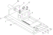
FIG. 1 is a schematic front side view of the present invention;
fig. 2 is a schematic diagram of the mobile unit structure of the present invention;
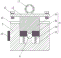
FIG. 3 is a right side sectional view of the left mold of the present invention;
fig. 4 is a schematic view of the structure of the thread groove of the present invention.
In the figure: the device comprises a mounting plate 1, a fixing plate 2, a fixing hole 3, a mounting groove 4, a left die 5, an injection molding hole 6, a moving unit 7, a motor 71, a moving block 72, a threaded rod 73, a limiting rod 74, a blocking unit 8, a connecting groove 81, a spring 82, a connecting block 83, a sliding block 84, an ejection unit 9, an electric telescopic rod 91, a fixed disk 92, a fixed column 93, a control switch group 10, an ejection shaft 11, a right die box 12, a bolt 13, a threaded groove 14, a fixed groove 15, a limiting plate 16, a pull ring 17 and a bottom plate 18.
Detailed Description
The technical solutions in the embodiments of the present invention will be described clearly and completely with reference to the accompanying drawings in the embodiments of the present invention, and it is obvious that the described embodiments are only some embodiments of the present invention, not all embodiments. Based on the embodiments in the present invention, all other embodiments obtained by a person skilled in the art without creative work belong to the protection scope of the present invention.
Referring to fig. 1-4, the present invention provides a technical solution: a plastic die with an automatic material head falling function comprises a mounting plate 1, a moving unit 7, a blocking unit 8, an ejection unit 9 and a right die box 12;
mounting plate 1: two corresponding fixed plates 2 are fixed on the upper side surface of the mounting plate 1, a mounting groove 4 is formed in the right end of the upper side surface of the mounting plate 1, a left mold 5 is fixed at the left end of the upper side surface of the mounting plate 1, and an injection molding hole 6 is formed in the middle of the left mold 5;
the moving unit 7: the moving unit 7 comprises a motor 71, a moving block 72, a threaded rod 73 and a limiting rod 74, the motor 71 is mounted on the right side surface of the mounting plate 1, a threaded hole is formed in the front side edge of the moving block 72, the threaded rod 73 is connected to the internal thread of the threaded hole, the right end surface of the threaded rod 73 is connected with the output shaft of the motor 71, the left end of the threaded rod 73 is rotatably connected to the left side wall inside the mounting groove 4, a sliding hole is formed in the front side edge of the moving block 72, the limiting rod 74 is slidably connected inside the sliding hole, the limiting rod 74 is fixed inside the mounting groove 4, and the right mold box 12 is driven;
right mold box 12: the right mold box 12 is fixed on the upper side surface of the moving block 72, an opening is formed in the left side surface of the right mold box 12, the right mold box 12 corresponds to the left mold 5, a mold core is fixed inside the right mold box 12, four corresponding through holes are formed in the right side surface of the right mold box 12, ejection shafts 11 are connected inside the through holes in a sliding mode, and the right ends of the four ejection shafts 11 are fixed on the left side surface of the right fixing plate 2;
the blocking unit 8: the separation unit 8 is installed inside the left mold 5, the separation unit 8 comprises a connecting groove 81, a spring 82, connecting blocks 83 and a sliding block 84, the connecting groove 81 is formed in the upper side face of the left mold 5, two corresponding springs 82 are fixed on the lower side wall inside the connecting groove 81, the two corresponding connecting blocks 83 are fixed at the upper end of the spring 82, the sliding block 84 is connected inside the connecting groove 81 in a sliding mode, and the material head is separated from a formed plastic product through the separation unit 8;
the ejection unit 9: the ejection unit 9 comprises an electric telescopic rod 91, a fixed disc 92 and a fixed column 93, the electric telescopic rod 91 is installed on the left side surface of the left fixed plate 2, a telescopic arm of the electric telescopic rod 91 is fixed on the left end surface of the fixed disc 92, the fixed column 93 is fixed on the right end surface of the fixed disc 92, the fixed column 93 corresponds to the injection molding hole 6, and the stub bar is ejected out through the ejection unit 9;
wherein: the die further comprises a control switch group 10, the control switch group 10 is installed on the front side face of the left die 5, the input end of the control switch group 10 is electrically connected with the output end of an external power supply, and the output end of the control switch group 10 is electrically connected with the input end of the motor 71 and the input end of the electric telescopic rod 91 respectively.
Wherein: the upper side face of the left die 5 is provided with a fixing groove 15, the upper side face of the sliding block 84 is fixedly provided with a limiting plate 16, the limiting plate 16 corresponds to the fixing groove 15, the upper side face of the limiting plate 16 is fixedly provided with a pull ring 17, and the sliding block 84 is pulled to move through the pull ring 17.
Wherein: two corresponding connecting holes are formed in the front edge portion and the rear edge portion of the limiting plate 16, a bolt 13 is connected to the inside of each connecting hole in a sliding mode, two corresponding thread grooves 14 are formed in the lower side wall of the inside of the fixing groove 15, the thread grooves 14 are matched with the bolt 13, and the limiting plate 16 is fixed through the bolt 13.
Wherein: a bottom plate 18 is fixed on the lower side surface of the mounting plate 1, and four corresponding fixing holes 3 are formed in the edge of the bottom plate 18.
When in use: the motor 71 is controlled to rotate by the control switch group 10, the motor 71 rotates to drive the threaded rod 73 to rotate, the threaded rod 73 rotates to drive the right mold box 12 to move towards the left side to be in contact with the right side surface of the left mold 5, then the plastic in a molten state is injected into the left mold 5 and the right mold box 12 through the injection molding hole 6, after the injection molding is finished, the limiting plate 16 is pressed downwards through the pull ring 17, the limiting plate 16 moves downwards to drive the sliding block 84 to move downwards, the sliding block 84 moves downwards to block the injection molding hole 6, the two connecting blocks 83 are pressed downwards at the same time, after the limiting plate 16 completely enters the inside of the fixed groove 15, the two bolts 13 are in threaded connection with the inside of the threaded groove 14, then the plastic is waited for cooling, after the cooling is finished, the motor 71 is controlled to rotate backwards by the control switch group 10, the motor 71 drives the threaded rod 73 to rotate backwards, four ejection shafts 11 of in-process that right side mold box 12 removed to the right side are ejecting with fashioned plastics, then unload two bolts 13, unload the back, pull out sliding block 84 through pull ring 17, pull out the back, control electric telescopic handle 91 work through control switch group 10, electric telescopic handle 91 work drives fixed column 93 and removes to the right side, fixed column 93 removes to the right side and enters into the inside of injection molding hole 6 ejecting with unnecessary stub bar from the inside of injection molding hole 6, makes through above device the utility model discloses can be very convenient ejecting with the stub bar.
It should be noted that the control switch group 10 disclosed in the present embodiment controls the operation of the motor 71 by a method commonly used in the art.
Although embodiments of the present invention have been shown and described, it will be appreciated by those skilled in the art that changes, modifications, substitutions and alterations can be made in these embodiments without departing from the principles and spirit of the invention, the scope of which is defined in the appended claims and their equivalents.
Claims (5)
1. The utility model provides an automatic plastic mold that drops of stub bar which characterized in that: comprises a mounting plate (1), a moving unit (7), a blocking unit (8), an ejection unit (9) and a right mould box (12);
mounting plate (1): two corresponding fixing plates (2) are fixed on the upper side surface of the mounting plate (1), a mounting groove (4) is formed in the right end of the upper side surface of the mounting plate (1), a left mold (5) is fixed on the left end of the upper side surface of the mounting plate (1), and an injection molding hole (6) is formed in the middle of the left mold (5);
mobile unit (7): the moving unit (7) comprises a motor (71), a moving block (72), a threaded rod (73) and a limiting rod (74), the motor (71) is installed on the right side face of the installation plate (1), a threaded hole is formed in the front side edge of the moving block (72), the threaded rod (73) is connected to the inner thread of the threaded hole, the right end face of the threaded rod (73) is connected with an output shaft of the motor (71), the left end of the threaded rod (73) is rotatably connected to the left side wall inside the installation groove (4), a sliding hole is formed in the front side edge of the moving block (72), the limiting rod (74) is connected to the inside of the sliding hole in a sliding mode, and the limiting rod (74) is fixed inside the installation groove (4);
right mold box (12): the right die box (12) is fixed on the upper side surface of the moving block (72), an opening is formed in the left side surface of the right die box (12), the right die box (12) corresponds to the left die (5), a die core is fixed inside the right die box (12), four corresponding through holes are formed in the right side surface of the right die box (12), ejection shafts (11) are connected inside the through holes in a sliding mode, and the right ends of the four ejection shafts (11) are fixed on the left side surface of the right fixing plate (2);
barrier unit (8): the blocking unit (8) is arranged inside the left die (5);
ejection unit (9): the ejection unit (9) comprises an electric telescopic rod (91), a fixed disc (92) and a fixed column (93), the electric telescopic rod (91) is installed on the left side face of the fixed plate (2) on the left side, a telescopic arm of the electric telescopic rod (91) is fixed on the left end face of the fixed disc (92), the fixed column (93) is fixed on the right end face of the fixed disc (92), and the fixed column (93) corresponds to the injection molding hole (6);
wherein: still include control switch group (10), install on the leading flank of left mould (5) control switch group (10), external power source's output is connected to the input electricity of control switch group (10), the input of electric connection motor (71) and electric telescopic handle (91) is respectively connected to the output of control switch group (10).
2. The plastic mold for automatically dropping the stub bar according to claim 1, wherein: separation unit (8) contain spread groove (81), spring (82), connecting block (83) and sliding block (84), spread groove (81) have been seted up on the last side of left side mould (5), be fixed with two corresponding spring (82) on the inside lower lateral wall of spread groove (81), the upper end of spring (82) is fixed with two corresponding connecting block (83), the inside sliding connection of spread groove (81) has sliding block (84).
3. The plastic mold for automatically dropping the stub bar according to claim 2, wherein: the die is characterized in that a fixing groove (15) is formed in the upper side face of the left die (5), a limiting plate (16) is fixed to the upper side face of the sliding block (84), the limiting plate (16) corresponds to the fixing groove (15) mutually, and a pull ring (17) is fixed to the upper side face of the limiting plate (16).
4. The plastic mold for automatically dropping the stub bar according to claim 3, wherein: two corresponding connecting holes are formed in the front edge portion and the rear edge portion of the limiting plate (16), a bolt (13) is connected to the inside of each connecting hole in a sliding mode, two corresponding thread grooves (14) are formed in the lower side wall of the inside of the fixing groove (15), and the thread grooves (14) are matched with the bolt (13).
5. The plastic mold for automatically dropping the stub bar according to claim 1, wherein: a bottom plate (18) is fixed on the lower side surface of the mounting plate (1), and four corresponding fixing holes (3) are formed in the edge of the bottom plate (18).
Priority Applications (1)
| Application Number | Priority Date | Filing Date | Title |
|---|---|---|---|
| CN202020199912.7U CN211941860U (en) | 2020-02-24 | 2020-02-24 | Plastic mold with automatic falling material head |
Applications Claiming Priority (1)
| Application Number | Priority Date | Filing Date | Title |
|---|---|---|---|
| CN202020199912.7U CN211941860U (en) | 2020-02-24 | 2020-02-24 | Plastic mold with automatic falling material head |
Publications (1)
| Publication Number | Publication Date |
|---|---|
| CN211941860U true CN211941860U (en) | 2020-11-17 |
Family
ID=73196215
Family Applications (1)
| Application Number | Title | Priority Date | Filing Date |
|---|---|---|---|
| CN202020199912.7U Expired - Fee Related CN211941860U (en) | 2020-02-24 | 2020-02-24 | Plastic mold with automatic falling material head |
Country Status (1)
| Country | Link |
|---|---|
| CN (1) | CN211941860U (en) |
Cited By (1)
| Publication number | Priority date | Publication date | Assignee | Title |
|---|---|---|---|---|
| CN113771309A (en) * | 2021-08-19 | 2021-12-10 | 浙江捷众科技股份有限公司 | Processing technology and production equipment for automobile front wiper motor gear |
-
2020
- 2020-02-24 CN CN202020199912.7U patent/CN211941860U/en not_active Expired - Fee Related
Cited By (1)
| Publication number | Priority date | Publication date | Assignee | Title |
|---|---|---|---|---|
| CN113771309A (en) * | 2021-08-19 | 2021-12-10 | 浙江捷众科技股份有限公司 | Processing technology and production equipment for automobile front wiper motor gear |
Similar Documents
| Publication | Publication Date | Title |
|---|---|---|
| CN211941860U (en) | Plastic mold with automatic falling material head | |
| CN212288505U (en) | Plastic injection mold is used in plastic production with heat dissipation function | |
| CN209699790U (en) | A kind of injection mold cavity ejection effort-saving mechanism | |
| CN214188285U (en) | But rapid prototyping's cell-phone inner panel injection mold | |
| CN214926670U (en) | Mould structure with auxiliary stand drops automatically | |
| CN212948851U (en) | Continuous multi-specification injection molding device | |
| CN211683317U (en) | Injection mold with ejection device | |
| CN211917548U (en) | Product drawing of patterns shape mechanism of preapring for an unfavorable turn of events | |
| CN210126234U (en) | Mold closing device for injection molding machine | |
| CN217293247U (en) | Mould is used in switching power supply shell production convenient to get material | |
| CN214026968U (en) | Injection mold with automatic cutout mechanism | |
| CN214294182U (en) | Injection mold who possesses bullet material function | |
| CN219903194U (en) | Mobile phone shell mold convenient for demolding | |
| CN214395242U (en) | Mould is used in switching power supply shell production convenient to get material | |
| CN214137285U (en) | Blow molding mechanism of blow molding machine | |
| CN213260819U (en) | Injection mold convenient to drawing of patterns | |
| CN220826251U (en) | Injection mold forming device | |
| CN216329845U (en) | Armrest is bullet material mechanism for injection mold | |
| CN217370044U (en) | Forming device is used in production of railhead planer tool | |
| CN218256192U (en) | Swing link type double-push-plate secondary ejection die | |
| CN220464464U (en) | Rubber mold stub bar ejection mechanism | |
| CN219213931U (en) | Die carrier capable of assisting stripping | |
| CN217573829U (en) | Quick demoulding mechanism of injection mould | |
| CN220562074U (en) | Mobile phone outer frame forming die convenient for demolding | |
| CN215661649U (en) | Helical gear injection mold convenient to drawing of patterns |
Legal Events
| Date | Code | Title | Description |
|---|---|---|---|
| GR01 | Patent grant | ||
| GR01 | Patent grant | ||
| CF01 | Termination of patent right due to non-payment of annual fee |
Granted publication date: 20201117 Termination date: 20210224 |
|
| CF01 | Termination of patent right due to non-payment of annual fee |