CN211941270U - A processing apparatus for panel - Google Patents
A processing apparatus for panel Download PDFInfo
- Publication number
- CN211941270U CN211941270U CN201921842382.7U CN201921842382U CN211941270U CN 211941270 U CN211941270 U CN 211941270U CN 201921842382 U CN201921842382 U CN 201921842382U CN 211941270 U CN211941270 U CN 211941270U
- Authority
- CN
- China
- Prior art keywords
- linear motor
- cutting
- motor
- door
- workbench
- Prior art date
- Legal status (The legal status is an assumption and is not a legal conclusion. Google has not performed a legal analysis and makes no representation as to the accuracy of the status listed.)
- Active
Links
Images


Landscapes
- Finish Polishing, Edge Sharpening, And Grinding By Specific Grinding Devices (AREA)
Abstract
The utility model relates to a processing apparatus for panel relates to panel processing field, has solved the processing equipment among the prior art, is the cutting, and when the cutting finishes, still need the manual work to punch and polish, the problem that wastes time and energy. The technical characteristics are that the device comprises a workbench, a cutting mechanism, a polishing mechanism and a punching mechanism, wherein the cutting mechanism, the polishing mechanism and the punching mechanism are arranged on the workbench; the cutting mechanism comprises a first door-shaped frame, a sliding part, a lifting part and a cutting part; the first door-shaped frame is arranged at the left end of the upper surface of the workbench, the sliding part is arranged on the inner lower surface of the first door-shaped frame, the lifting part is arranged on the lower surface of the sliding part, and the cutting part is arranged on the lifting part; the polishing mechanism is used for polishing the plate; the punching mechanism is used for punching the plate. This device easy operation, low in cost can cut the not unidimensional panel of different length, can also punch and polish when the cutting finishes, has saved manpower and materials.
Description
Technical Field
The utility model relates to a panel processing technology field, in particular to processing apparatus for panel.
Background
Cabinet use began in the summer season, when called "box". In the time of the Ming and Qing dynasty, the cabinet becomes the necessary indoor furniture and the shape is already established. The Ming and Qing dynasty cabinet can be divided into a square cabinet, a round cabinet and a bright grid cabinet according to the type, and the type is different, and the components are also different. Cabinet furniture mainly refers to cabinets made of wood, artificial boards or metal and the like and having different purposes.
At present, before the cupboard assembly, often need process the panel that needs to use, however, current processing equipment is the cutting, and when the cutting was finished, still need the manual work to punch and polish, so not only waste time and energy, increased the required space of producer production equally, consequently it is very necessary to design a processing apparatus for panel.
SUMMERY OF THE UTILITY MODEL
The utility model discloses solve the processing equipment among the prior art, be the cutting, when the cutting finishes, still need the manual work to punch and polish, waste time and energy technical problem provides a processing apparatus for panel.
In order to solve the technical problem, the technical scheme of the utility model is specifically as follows:
a processing device for a plate comprises a workbench, a cutting mechanism, a grinding mechanism and a punching mechanism, wherein the cutting mechanism, the grinding mechanism and the punching mechanism are arranged on the workbench;
the cutting mechanism comprises a first door-shaped frame, a sliding part, a lifting part and a cutting part;
the first door-shaped frame is arranged at the left end of the upper surface of the workbench, the sliding part is arranged on the inner lower surface of the first door-shaped frame, the lifting part is arranged on the lower surface of the sliding part, and the cutting part is arranged on the lifting part;
the polishing mechanism is used for polishing the plate;
the punching mechanism is used for punching the plate.
Preferably, the sliding part includes a first bar-shaped slide, a first linear motor, and a first slider;
the first linear slideway is arranged on the inner upper surface of the first door-shaped frame, the first linear motor is arranged inside the first linear slideway, and the first sliding block is arranged inside the first linear slideway and is positioned on the side surface of the driving end of the first linear motor.
Preferably, the lifting unit includes a second linear motor and a base plate;
the second linear motor is arranged on the lower surface of the first sliding block, and the bottom plate is arranged on the lower surface of the driving end of the second linear motor.
Preferably, the cutting part comprises a first rotating motor and a cutting knife;
the first rotating motor is arranged on the lower surface of the bottom plate, and the cutting knife is sleeved on the driving end of the first rotating motor.
Preferably, the punching mechanism comprises a second portal frame, a fourth linear motor, a second rotating motor and a drill bit;
the second portal frame is arranged on the upper surface of the workbench, the fourth linear motor is arranged on the inner upper surface of the second portal frame, the second rotary device is arranged on the lower surface of the driving end of the fourth linear motor, and the drill bit is in threaded connection with the driving end of the second rotary motor.
Preferably, the polishing mechanism comprises a third door-shaped frame, a third rotating motor, a rotating rod, a rotating cylinder, a third linear motor, an n-shaped connecting plate and replaceable abrasive paper;
the third door-shaped frame is arranged at one end of the upper surface of the workbench, the third linear motor is arranged on the inner upper surface of the third door-shaped frame, the n-shaped connecting plate is arranged on the lower surface of the driving end of the third linear motor, the third rotating motor is arranged at the lower end of the side surface of the n-shaped connecting plate in a penetrating mode, the rotating rod is arranged in the n-shaped connecting plate, one end of the rotating rod is connected with the driving end of the third rotating motor, the rotating cylinder is sleeved on the rotating rod, and the replaceable abrasive paper is arranged on the rotating cylinder.
Preferably, the lower surface of the workbench is provided with two pairs of universal wheels, and the two pairs of universal wheels are provided with brake pads.
The utility model discloses following beneficial effect has:
this device easy operation, low in cost can cut the not unidimensional panel of different length, can also punch and polish when the cutting finishes, has saved manpower and materials, has reduced the waste in space, has reduced manufacturer's fund loss.
Drawings
The present invention will be described in further detail with reference to the accompanying drawings and specific embodiments.
Fig. 1 is a schematic structural diagram of a processing device for sheet materials according to the present invention;
FIG. 2 is a schematic structural view of the punching mechanism of the present invention;
FIG. 3 is a schematic structural view of the polishing mechanism of the present invention;
fig. 4 is a front view of the cutting mechanism of the present invention;
fig. 5 is a front view of a processing apparatus for sheet materials according to the present invention.
The reference numerals in the figures denote:
1. a work table; 2. a first gate frame; 3. a first bar-shaped slideway; 4. a first linear motor; 5. a first slider; 6. a second linear motor; 7. a base plate; 8. a first rotating electrical machine; 9. a cutting knife; 10. a second portal frame; 11. a fourth linear motor; 12. a second rotating electrical machine; 13. a drill bit; 14. a third gate frame; 15. a third rotating electrical machine; 16. rotating the rod; 17. a rotating cylinder; 18. a third linear motor; 19. An n-shaped connecting plate; 20. sand paper can be replaced; 21. a universal wheel; 22. a brake pad.
Detailed Description
The technical solutions in the embodiments of the present invention will be described clearly and completely with reference to the accompanying drawings in the embodiments of the present invention, and it is obvious that the described embodiments are only some embodiments of the present invention, not all embodiments. Based on the embodiments in the present invention, all other embodiments obtained by a person skilled in the art without creative work belong to the protection scope of the present invention.
Referring to fig. 1-5, a processing device for a plate includes a worktable 1, a cutting mechanism, a polishing mechanism and a punching mechanism disposed on the worktable;
the cutting mechanism comprises a first door-shaped frame 2, a sliding part, a lifting part and a cutting part;
the first door-shaped frame is arranged at the left end of the upper surface of the workbench 1, the sliding part is arranged on the inner lower surface of the first door-shaped frame 2, the lifting part is arranged on the lower surface of the sliding part, and the cutting part is arranged on the lifting part;
the polishing mechanism is used for polishing the plate;
the punching mechanism is used for punching the plate.
The sliding part comprises a first strip-shaped slideway 3, a first linear motor 4 and a first sliding block 5;
the first strip-shaped slideway 3 is arranged on the inner upper surface of the first door-shaped frame 2, the first linear motor 4 is arranged inside the first strip-shaped slideway 3, and the first sliding block 5 is arranged inside the first strip-shaped slideway 3 and is positioned on the side surface of the driving end of the first linear motor 4.
The lifting part comprises a second linear motor 6 and a bottom plate 7;
the second linear motor 6 is arranged on the lower surface of the first sliding block 5, and the bottom plate 7 is arranged on the lower surface of the driving end of the second linear motor 6.
The cutting part comprises a first rotating motor 8 and a cutting knife 9;
the first rotating motor 8 is arranged on the lower surface of the bottom plate 7, and the cutting knife 9 is sleeved on the driving end of the first rotating motor 8.
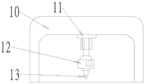
The punching mechanism comprises a second portal frame 10, a fourth linear motor 11, a second rotating motor 12 and a drill bit 13;
the second portal frame 10 is disposed on the upper surface of the worktable 1, the fourth linear motor 11 is disposed on the inner upper surface of the second portal frame 10, the second rotation is disposed on the lower surface of the driving end of the fourth linear motor 11, and the drill bit 13 is screwed on the driving end of the second rotary motor 12.
The grinding mechanism comprises a third door-shaped frame 14, a third rotating motor 15, a rotating rod 16, a rotating cylinder 17, a third linear motor 18, an n-shaped connecting plate 19 and replaceable abrasive paper 20;
the third door-shaped frame 14 is arranged at one end of the upper surface of the workbench 1, the third linear motor 18 is arranged on the inner upper surface of the third door-shaped frame 14, the n-shaped connecting plate 19 is arranged on the lower surface of the driving end of the third linear motor 18, the third rotary motor 15 is arranged at the lower end of the side surface of the n-shaped connecting plate 19 in a penetrating manner, the rotating rod 16 is arranged in the n-shaped connecting plate 19, one end of the rotating rod 16 is connected with the driving end of the third rotary motor 15, the rotating cylinder 17 is sleeved on the rotating rod 16, and the replaceable abrasive paper 20 is arranged on the rotating cylinder 17.
The lower surface of the workbench 1 is provided with two pairs of universal wheels 21, and the two pairs of universal wheels 21 are provided with brake pads 22.
The working principle is as follows:
firstly, the workbench 1 is moved through the universal wheel 21, when the workbench is moved to a designated working place, the universal wheel 21 can be fixed through the brake block 22, the phenomenon of shaking during working is avoided, then, a plate is placed on the workbench 1, the first slide block 5 can be driven by the first linear motor 4 to slide on the first strip-shaped slide way 3, then, the second linear motor 6 can drive the first rotating motor 8 to move downwards, then, the first rotating motor 8 can drive the cutting knife 9 to cut the plate, then, the second rotating motor 12 is driven by the fourth linear motor 11 to move downwards, then, the second rotating motor 12 drives the drill bit 13 to drill, if hole rotation is not needed, the fourth linear motor 11 can drive the second rotating motor 12 to move towards the inner upper surface close to the second door-shaped frame 10, hole drilling can be finished by driving the n-shaped connecting plate 19 to move downwards through the third linear motor 18, thereby let and to change abrasive paper 20 and panel on the section of thick bamboo 17 and contact, later third rotating electrical machines 15 drive dwang 16 and rotate to let dwang 16 drive and to change that abrasive paper 20 that can replace on the section of thick bamboo 17 rotates and polish burr etc..
It should be understood that the above examples are only for clarity of illustration and are not intended to limit the embodiments. Other variations and modifications will be apparent to persons skilled in the art in light of the above description. And are neither required nor exhaustive of all embodiments. And obvious variations or modifications therefrom are within the scope of the invention.
Claims (7)
1. A processing device for a plate is characterized by comprising a workbench (1), a cutting mechanism, a grinding mechanism and a punching mechanism, wherein the cutting mechanism, the grinding mechanism and the punching mechanism are arranged on the workbench ();
the cutting mechanism comprises a first door-shaped frame (2), a sliding part, a lifting part and a cutting part;
the first door-shaped frame is arranged at the left end of the upper surface of the workbench (1), the sliding part is arranged on the inner lower surface of the first door-shaped frame (2), the lifting part is arranged on the lower surface of the sliding part, and the cutting part is arranged on the lifting part;
the polishing mechanism is used for polishing the plate;
the punching mechanism is used for punching the plate.
2. A handling device for sheets according to claim 1, characterised in that said sliding portion comprises a first linear slide (3), a first linear motor (4) and a first slide (5);
the first strip-shaped slide way (3) is arranged on the inner upper surface of the first door-shaped frame (2), the first linear motor (4) is arranged inside the first strip-shaped slide way (3), and the first sliding block (5) is arranged inside the first strip-shaped slide way (3) and is positioned on the side surface of the driving end of the first linear motor (4).
3. A handling device for slabs according to claim 2, characterized in that said lifting portion comprises a second linear motor (6) and a bottom plate (7);
the second linear motor (6) is arranged on the lower surface of the first sliding block (5), and the bottom plate (7) is arranged on the lower surface of the driving end of the second linear motor (6).
4. A handling unit for sheets according to claim 3, characterised in that said cutting section comprises a first rotating motor (8) and a cutting knife (9);
the first rotating motor (8) is arranged on the lower surface of the bottom plate (7), and the cutting knife (9) is sleeved on the driving end of the first rotating motor (8).
5. A handling unit for sheets according to claim 1, wherein said punching mechanism comprises a second portal frame (10), a fourth linear motor (11), a second rotary motor (12) and a drill (13);
the second portal frame (10) is arranged on the upper surface of the workbench (1), the fourth linear motor (11) is arranged on the inner upper surface of the second portal frame (10), the second rotary device is arranged on the lower surface of the driving end of the fourth linear motor (11), and the drill bit (13) is in threaded connection with the driving end of the second rotary motor (12).
6. A processing device for boards according to claim 1, wherein the sanding mechanism comprises a third portal frame (14), a third rotating motor (15), a turning bar (16), a turning cylinder (17), a third linear motor (18), an n-shaped web (19) and replaceable sandpaper (20);
the third door type frame (14) is arranged at one end of the upper surface of the workbench (1), the third linear motor (18) is arranged on the inner upper surface of the third door type frame (14), the n-shaped connecting plate (19) is arranged on the lower surface of the driving end of the third linear motor (18), the third rotary motor (15) is arranged at the lower end of the side surface of the n-shaped connecting plate (19) in a penetrating mode, the rotating rod (16) is arranged in the n-shaped connecting plate (19), one end of the rotating rod (16) is connected with the driving end of the third rotary motor (15), the rotating cylinder (17) is sleeved on the rotating rod (16), and the replaceable abrasive paper (20) is arranged on the rotating cylinder (17).
7. A handling unit for slabs according to claim 1, characterized in that the lower surface of said table (1) is provided with two pairs of universal wheels (21), said pairs of universal wheels (21) being provided with brake pads (22).
Priority Applications (1)
| Application Number | Priority Date | Filing Date | Title |
|---|---|---|---|
| CN201921842382.7U CN211941270U (en) | 2019-10-29 | 2019-10-29 | A processing apparatus for panel |
Applications Claiming Priority (1)
| Application Number | Priority Date | Filing Date | Title |
|---|---|---|---|
| CN201921842382.7U CN211941270U (en) | 2019-10-29 | 2019-10-29 | A processing apparatus for panel |
Publications (1)
| Publication Number | Publication Date |
|---|---|
| CN211941270U true CN211941270U (en) | 2020-11-17 |
Family
ID=73167076
Family Applications (1)
| Application Number | Title | Priority Date | Filing Date |
|---|---|---|---|
| CN201921842382.7U Active CN211941270U (en) | 2019-10-29 | 2019-10-29 | A processing apparatus for panel |
Country Status (1)
| Country | Link |
|---|---|
| CN (1) | CN211941270U (en) |
-
2019
- 2019-10-29 CN CN201921842382.7U patent/CN211941270U/en active Active
Similar Documents
| Publication | Publication Date | Title |
|---|---|---|
| CN110756651A (en) | Punching device for hardware production | |
| CN207548954U (en) | A kind of board cutting device with high efficiency cutting | |
| CN212218017U (en) | Steel plate deburring equipment for daily hardware production and machining | |
| CN112296848A (en) | Plate-shaped part polishing device for hardware tool machining and using method thereof | |
| CN103753385B (en) | A kind of with base, chamfering and the Multifunctional mill head unit except mill | |
| CN211941270U (en) | A processing apparatus for panel | |
| CN108421884A (en) | It is a kind of to move up and down type perforating device for hardware plank | |
| CN210938117U (en) | Gantry single-drive high-speed platform | |
| CN209792759U (en) | Aluminum product cutting machine with automatic chip collecting function | |
| CN108145505A (en) | One kind is convenient for lathe handling equipment | |
| CN209737796U (en) | Building decorative plate perforating device | |
| CN218052796U (en) | Hollow plate cutting machine | |
| CN218696716U (en) | One-way mandrel surface grinding device convenient to adjust and used for refrigeration equipment | |
| CN206614350U (en) | A kind of round shape material sanding apparatus | |
| CN115781294A (en) | Environment-friendly conveying cylinder turning and polishing integrated machine and using method thereof | |
| CN213437375U (en) | Machine tool convenient for drilling mechanical workpiece | |
| CN218462420U (en) | Quick drilling equipment of timber | |
| CN211221113U (en) | Novel cupboard processing device | |
| CN106521917A (en) | Novel cutter lifting and rotating device of computerized cutting bed | |
| CN219094647U (en) | Multidirectional positive angle grinding tool of precision grinding machine | |
| CN221455290U (en) | Stone processing grinding device for building | |
| CN215041775U (en) | Multifunctional stone carving workbench | |
| CN214871111U (en) | Punching and polishing device | |
| CN219583054U (en) | Panel perforating device | |
| CN216656562U (en) | Cutting device that machining used |
Legal Events
| Date | Code | Title | Description |
|---|---|---|---|
| GR01 | Patent grant | ||
| GR01 | Patent grant |