CN211933726U - Convenient radiating food electric baking appliance - Google Patents
Convenient radiating food electric baking appliance Download PDFInfo
- Publication number
- CN211933726U CN211933726U CN202020214505.9U CN202020214505U CN211933726U CN 211933726 U CN211933726 U CN 211933726U CN 202020214505 U CN202020214505 U CN 202020214505U CN 211933726 U CN211933726 U CN 211933726U
- Authority
- CN
- China
- Prior art keywords
- air
- air guide
- outlet
- air outlet
- hot
- Prior art date
- Legal status (The legal status is an assumption and is not a legal conclusion. Google has not performed a legal analysis and makes no representation as to the accuracy of the status listed.)
- Active
Links
Images


Abstract
The utility model discloses a make things convenient for radiating food electric baking apparatus, including organism (1) and locate pot body (2) and hot-blast subassembly in organism (1), wherein, organism (1) is including shell (11), locate inner shell (12) in shell (11) and locate wind-guiding dish (13) in inner shell (12), wind-guiding dish (13) are for cold wind chamber (121) and hot-blast chamber (122) with the inner space separation of inner shell (12), first air outlet (1122) have been seted up on shell (11), third air outlet (132) of air current discharge to first air outlet (1122) in heat supply wind chamber (122) have been seted up on wind-guiding dish (13), be equipped with on the inner wall of wind-guiding dish (13) and guide the air guide strip (133) of air current in hot-blast chamber (122) to third air outlet (132). Compared with the prior art, the utility model discloses a food electric roaster can in time discharge unnecessary heat.
Description
Technical Field
The utility model relates to a kitchen appliance technical field specifically indicates a convenient radiating food electric baking utensil.
Background
The air fryer is a novel household appliance for frying food by utilizing a high-speed and high-temperature air circulation technology, the oil of the manufactured food can be reduced by 80 percent compared with that of the traditional electric fryer, and the air fryer is easy to clean in daily use, is safe and economical and is favored by people.
Current air is fried pot generally includes the organism, be formed with the culinary art chamber in the organism, be equipped with the hot-blast subassembly that can send into high-temperature air to culinary art intracavity portion in the organism, the culinary art intracavity is equipped with the pot body that is used for holding food, the high-temperature hot-blast that utilizes hot-blast subassembly during operation to produce heats the edible material in the pot, hot-air and food fully contact, utilize the food surface to lose moisture fast in the twinkling of an eye, or in addition the grease that food self produced, make the food surface form crisp taste, the effect of being fried appears. The concrete structure can be found in the invention patent of patent application No. CN201710570933.8 (publication No. CN107233007A) of an air fryer with a simple assembly structure.
However, in the existing air fryer, the power of the heating element is higher, so that the temperature in the cooking cavity is very high, and the redundant heat cannot be sent out, so that the internal temperature of the whole machine is very high.
SUMMERY OF THE UTILITY MODEL
The utility model aims to solve the first technical problem that to prior art's current situation, provide a can be in time with unnecessary heat exhaust food electric baking utensil.
The second technical problem to be solved by the present invention is to provide a food electric roaster capable of avoiding hot wind from entering the body.
The utility model provides a technical scheme that above-mentioned first technical problem adopted does: a food electric roaster convenient for heat dissipation comprises
The machine body comprises an outer shell, an inner shell arranged in the outer shell and an air guide disc arranged in the inner shell, wherein an interlayer is formed between the outer wall of the inner shell and the inner wall of the outer shell, the air guide disc divides the inner space of the inner shell into a cold air cavity positioned at the upper part and hot air positioned at the lower part, and a cooking cavity is formed at the lower part of the hot air cavity;
the pot body is accommodated in the cooking cavity; and
the hot air assembly is arranged in the machine body and can send high-temperature gas to the pot body;
the method is characterized in that:
the air guide plate is characterized in that the shell is provided with a first air outlet, the air guide plate is provided with a third air outlet, a second air duct is arranged in the machine body, an inlet of the second air duct is communicated with the third air outlet, an outlet of the second air duct is communicated with the first air outlet, and an air guide strip capable of guiding air flow in the hot air cavity to the third air outlet is arranged on the inner wall of the air guide plate.
In order to block hot air and avoid continuous circulating motion of the air guide strip in the hot air cavity, the air guide strip is positioned on one side of the third air outlet, an air guide surface is arranged on the air guide strip, and an included angle between the air guide surface and the plane where the third air outlet is positioned is 60-120 degrees.
In order to form the air guide surface, the air guide strip may be designed as a thin plate or a block with an inclined surface.
In order to facilitate the processing of the air guide strips, the edge of the air guide disc, which is positioned on one side of the third air outlet, is bent inwards and extends to form the air guide strips.
In order to further solve the second technical problem, the inner casing is provided with a second air outlet for discharging the air flow in the cold air cavity to the first air outlet, the machine body is internally provided with a first air duct and a second air duct which are independent from each other, an inlet of the first air duct is communicated with the second air outlet, an outlet of the first air duct is communicated with the first air outlet, an inlet of the second air duct is communicated with the third air outlet, and an outlet of the second air duct is communicated with the first air outlet.
In order to realize the formation of the first air duct and the second air duct, the edge of the inner shell, which is positioned at the second air outlet, is bent outwards and extends to form a first air guide pipeline, the end part of the first air guide pipeline is abutted against the inner wall of the outer shell, a second air guide pipeline is arranged inside the first air guide pipeline, and the second air guide pipeline divides the inner space of the first air guide pipeline into the first air duct positioned at the periphery and the second air duct positioned in the middle.
In order to realize the sealed communication between the inlet of the second air duct and the third air outlet, a sealing ring is sleeved at the edge of the second air guide pipeline on one side of the inlet of the second air duct, and the sealing ring is abutted against the outer wall of the air guide disc, so that hot air in the hot air cavity can be prevented from entering the cold air cavity through a gap.
In order to realize the installation of the second air guide channel in the first air guide channel, a connecting piece used for connecting the inner wall of the first air guide pipeline and the outer wall of the second air guide pipeline is arranged in the first air channel.
In order to realize the installation stability of the second air guide channel, the number of the connecting pieces is at least two, and the connecting pieces are distributed in the first air channel at intervals along the circumferential direction.
In order to ensure the circulation of hot air in the hot air cavity and improve the heating effect, the hot air assembly is positioned at the upper part of the hot air cavity and comprises a heating element and a thermal circulation fan positioned above the heating element.
In order to ensure the circulation of cold air in the machine body and improve the heat radiation effect, the air conditioner also comprises
The motor is arranged in the interlayer; and
the cooling fan is arranged in the cold air cavity and is in transmission connection with an output shaft of the motor;
the heat circulation fan is in transmission connection with an output shaft of the motor.
Compared with the prior art, the utility model has the advantages of: through wind-guiding strip on the inner wall of aviation baffle, can block partly hot-blastly, avoid it to continue at hot-blast chamber mesocycle motion, in time with the transmission of unnecessary heat guide to third air outlet, convenient heat dissipation reduces the inside temperature of complete machine.
Drawings
Fig. 1 is a schematic perspective view of an embodiment of an electric food roaster according to the present invention;
FIG. 2 is a longitudinal cross-sectional view of the electric food grill of FIG. 1 with the motor omitted;
FIG. 3 is an enlarged view of portion I of FIG. 2;
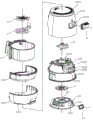
FIG. 4 is an exploded perspective view of the electric food roaster of FIG. 1 in another orientation;
fig. 5 is a schematic perspective view of an air guiding plate according to an embodiment of the present invention.
Detailed Description
The present invention will be described in further detail with reference to the following embodiments.
As shown in fig. 1 to 5, the preferred embodiment of the present invention will be described by taking an air fryer as an example. The electric food roaster comprises a main body 1, a pan body 2, a heating element 3, a motor 4, a cooling fan 5 and a heat circulation fan 6.
The machine body 1 includes an outer casing 11, an inner casing 12 disposed in the outer casing 11, and an air guiding disc 13 disposed in the inner casing 12, an interlayer 111 is formed between an outer wall of the inner casing 12 and an inner wall of the outer casing 11, the air guiding disc 13 divides an inner space of the inner casing 12 into a cold air cavity 121 located at an upper portion and a hot air cavity 122 located at a lower portion, and a cooking cavity 1221 is formed at a lower portion of the hot air cavity 122.
Specifically, the housing 11 includes an upper housing 112 and a lower housing 113 which are connected in a vertically-matched manner, a first air inlet 1121 which communicates the interlayer 111 and the outside atmosphere is formed in both the top wall of the upper housing 112 and the bottom wall of the lower housing 113, a first air outlet 1122 which communicates the interlayer 111 and the outside atmosphere is formed in the side wall of the upper housing 112, and an air outlet cover 14 is formed in an upper cover of the first air outlet 1122; the inner shell 12 comprises a motor frame 123 and an inner container 124 which are connected in a vertically matched manner, and a second air inlet 1231 and a second air outlet 1232 which are communicated with the interlayer 111 and the cold air cavity 121 are respectively formed in the top wall and the side wall of the motor frame 123; the top wall and the side wall of the air guiding disc 13 are respectively provided with a third air inlet 131 and a third air outlet 132 which are communicated with the cold air cavity 121 and the hot air cavity 122.
The edge of the motor frame 123 located at the second air outlet 1232 is bent and extended outward to form a first air guiding duct 1233, the end of the first air guiding duct 1233 abuts against the inner wall of the upper housing 112, a second air guiding duct 1234 is arranged inside the first air guiding duct 1233, the second air guiding duct 1234 divides the inner space of the first air guiding duct 1233 into a first air duct 1235 located at the periphery and a second air duct 1236 located in the middle, a sealing ring 15 is sleeved at the edge of the second air guiding duct 1234 located at the inlet side of the second air duct 1236, and the sealing ring 15 abuts against the outer wall of the air guiding disc 13; at least two connecting pieces 1237 for connecting the inner wall of the first air guide pipe 1233 and the outer wall of the second air guide pipe 1234 are arranged in the first air duct 1235 at intervals along the circumferential direction; the first air duct 1235 and the second air duct 1236 are independent from each other, the inlet of the first air duct 1235 is communicated with the second air outlet 1232, the outlet of the first air duct 1235 is communicated with the first air outlet 1122, the inlet of the second air duct 1236 is communicated with the third air outlet 132 in a sealing manner, and the outlet of the second air duct 1236 is communicated with the first air outlet 1122.
The edge of the air guiding plate 13 on one side of the third air outlet 132 is bent inward to form an air guiding strip 133 for guiding the air flow in the hot air cavity 122 to the third air outlet 132. The wind guide strip 133 has a wind guide surface 1331, and an included angle between the wind guide surface 1331 and the plane of the third wind outlet 132 is 60 to 120 °, and in this embodiment, the included angle is about 90 °. The arrangement of the air guide strips 133 can block a part of hot air, so that the hot air is prevented from continuously circulating in the hot air cavity 122, redundant heat is transmitted out in time, and the internal temperature of the whole machine is reduced.
The pot 2 is accommodated in the cooking chamber 1221, in this embodiment, the side walls of the outer shell 11 and the inner shell 12 have corresponding openings through which the pot 2 can be drawn into and out of the cooking chamber 1221.
The heating element 3 is provided at an upper portion of the hot wind chamber 122. In this embodiment, the heating element 3 is a spirally wound heating tube.
The motor 4 is disposed in the interlayer 111 and above the motor mount 123.
The cooling fan 5 is arranged in the cold air cavity 121 and is in transmission connection with an output shaft of the motor 4. The cooling fan 5 can suck the external atmosphere into the cold air chamber 121 through the first air inlet 1121 and the second air inlet 1231 in sequence, and discharge the external atmosphere through the second air outlet 1232 and the first air outlet 1122 in sequence.
The heat circulation fan 6 is arranged in the hot air cavity 122 and above the heating element 3, and is in transmission connection with the output shaft of the motor 4. The hot air component consisting of the heat circulating fan 6 and the heating element 3 blows hot air to the food materials in the pot body 2, takes away water in the food through the hot air and heats the food, thereby achieving the effect and the taste of frying various foods, chips, fishes and other fried foods.
The working principle of the utility model is as follows: putting the pot body 2 containing food materials into the cooking cavity 1121, starting the food electric baking appliance, driving the cooling fan 5 and the thermal circulation fan 6 to rotate by the motor 4, sucking the external air into the interlayer 111 from the first air inlet 1121, cooling the components, particularly the housing 11, by the internal circulation of the cold air in the interlayer 111, finally allowing the air flow to enter the cold air cavity 121 from the second air inlet 1231 under the action of the cooling fan 5, discharging a part of the air flow in the cold air cavity 121 to the external air through the second air outlet 1232, the first air duct 1235 and the first air outlet 1122 in sequence, blowing the other part of the air flow into the hot air cavity 122 from the third air inlet 131, heating the air flow by the heating element 3 to form hot air, blowing the hot air to the pot body 2 by the thermal circulation fan 6, heating the food materials in the pot body 2, and finally blowing the hot air in the hot air cavity 122 through the third air outlet 132 and the third air outlet 133 in sequence, In second wind channel 1236, first air outlet 1122 discharged the external atmosphere, the setting of wind-guiding strip 133 can block partly hot-blastly, avoid it to continue at hot-blast chamber 122 mesocycle motion, in time go out unnecessary heat conveying, reduce the inside temperature of complete machine, two kinds of air currents can be avoided gathering in organism 1 in the setting of first wind channel 1235 and second wind channel 1236 in addition, reduce the hot-blastly condition of running to organism 1 in to reduce organism 1 temperature all around.
Claims (10)
1. A food electric roaster convenient for heat dissipation comprises
The machine body (1) comprises an outer shell (11), an inner shell (12) arranged in the outer shell (11) and an air guide disc (13) arranged in the inner shell (12), wherein an interlayer (111) is formed between the outer wall of the inner shell (12) and the inner wall of the outer shell (11), the air guide disc (13) divides the inner space of the inner shell (12) into a cold air cavity (121) positioned at the upper part and a hot air cavity (122) positioned at the lower part, and a cooking cavity (1221) is formed at the lower part of the hot air cavity (122);
a pan (2) housed in said cooking chamber (1221); and
the hot air assembly is arranged in the machine body (1) and can send high-temperature gas to the pot body (2);
the method is characterized in that:
the air conditioner is characterized in that a first air outlet (1122) is formed in the shell (11), a third air outlet (132) is formed in the air guide disc (13), a second air duct (1236) is formed in the machine body (1), an inlet of the second air duct (1236) is communicated with the third air outlet (132), an outlet of the second air duct (1236) is communicated with the first air outlet (1122), and air guide strips (133) capable of guiding air flow in the hot air cavity (122) to the third air outlet (132) are arranged on the inner wall of the air guide disc (13).
2. The electric food baking appliance according to claim 1, wherein: the air guide strip (133) is located on one side of the third air outlet (132), an air guide surface (1331) is arranged on the air guide strip (133), and an included angle formed between the air guide surface (1331) and the plane where the third air outlet (132) is located is 60-120 degrees.
3. The electric food baking appliance according to claim 2, wherein: the edge of the air guide disc (13) on one side of the third air outlet (132) is bent inwards to form the air guide strip (133).
4. The electric food baking appliance according to claim 1, wherein: the air conditioner is characterized in that a second air outlet (1232) is formed in the inner shell (12), a first air duct (1235) which is independently arranged relative to the second air duct (1236) is arranged in the machine body (1), an inlet of the first air duct (1235) is communicated with the second air outlet (1232), and an outlet of the first air duct (1235) is communicated with the first air outlet (1122).
5. The electric food baking appliance according to claim 4, wherein: the edge of the inner shell (12) located at the second air outlet (1232) is bent outwards and extends to form a first air guide pipeline (1233), the end of the first air guide pipeline (1233) is abutted to the inner wall of the outer shell (11), a second air guide pipeline (1234) is arranged inside the first air guide pipeline (1233), and the second air guide pipeline (1234) divides the inner space of the first air guide pipeline (1233) into a first air channel (1235) located at the periphery and a second air channel (1236) located in the middle.
6. The electric food baking appliance according to claim 5, wherein: the edge of the second air guide pipeline (1234) on one side of the inlet of the second air duct (1236) is sleeved with a sealing ring (15), and the sealing ring (15) is abutted to the outer wall of the air guide disc (13).
7. The electric food baking appliance according to claim 5, wherein: and a connecting piece (1237) used for connecting the inner wall of the first air guide pipeline (1233) and the outer wall of the second air guide pipeline (1234) is arranged in the first air duct (1235).
8. The electric food baking appliance according to claim 7, wherein: the number of the connecting pieces (1237) is at least two, and the connecting pieces are distributed in the first air duct (1235) at intervals along the circumferential direction.
9. A food electric grill according to any one of claims 1 to 8 wherein: the hot air assembly is positioned at the upper part of the hot air cavity (122), and comprises a heating element (3) and a heat circulating fan (6) positioned above the heating element (3).
10. The electric food baking appliance according to claim 9, wherein: also comprises
The motor (4) is arranged in the interlayer (111); and
the cooling fan (5) is arranged in the cold air cavity (121) and is in transmission connection with an output shaft of the motor (4);
the heat circulation fan (6) is in transmission connection with an output shaft of the motor (4).
Priority Applications (1)
| Application Number | Priority Date | Filing Date | Title |
|---|---|---|---|
| CN202020214505.9U CN211933726U (en) | 2020-02-26 | 2020-02-26 | Convenient radiating food electric baking appliance |
Applications Claiming Priority (1)
| Application Number | Priority Date | Filing Date | Title |
|---|---|---|---|
| CN202020214505.9U CN211933726U (en) | 2020-02-26 | 2020-02-26 | Convenient radiating food electric baking appliance |
Publications (1)
| Publication Number | Publication Date |
|---|---|
| CN211933726U true CN211933726U (en) | 2020-11-17 |
Family
ID=73196628
Family Applications (1)
| Application Number | Title | Priority Date | Filing Date |
|---|---|---|---|
| CN202020214505.9U Active CN211933726U (en) | 2020-02-26 | 2020-02-26 | Convenient radiating food electric baking appliance |
Country Status (1)
| Country | Link |
|---|---|
| CN (1) | CN211933726U (en) |
Cited By (1)
| Publication number | Priority date | Publication date | Assignee | Title |
|---|---|---|---|---|
| CN112545137A (en) * | 2020-12-07 | 2021-03-26 | 珠海格力电器股份有限公司 | Lunch box |
-
2020
- 2020-02-26 CN CN202020214505.9U patent/CN211933726U/en active Active
Cited By (1)
| Publication number | Priority date | Publication date | Assignee | Title |
|---|---|---|---|---|
| CN112545137A (en) * | 2020-12-07 | 2021-03-26 | 珠海格力电器股份有限公司 | Lunch box |
Similar Documents
| Publication | Publication Date | Title |
|---|---|---|
| CN110840285A (en) | Air fryer facilitating cooling of shell | |
| CN111184453A (en) | Food electric baking device with high heating efficiency | |
| CN210810617U (en) | Air fryer | |
| CN211933708U (en) | Air fryer | |
| CN110859523A (en) | Air fryer | |
| CN211933726U (en) | Convenient radiating food electric baking appliance | |
| CN211933725U (en) | Food electric baking device convenient for cooling machine body | |
| CN112674619A (en) | Air frying pan | |
| CN211933727U (en) | Avoid horizontal exhaust food electric baking utensil of steam | |
| CN211155318U (en) | Air fryer | |
| CN212307609U (en) | Food electric baking device with high heating efficiency | |
| CN211582736U (en) | Air fryer facilitating cooling of shell | |
| CN217792638U (en) | Air blast furnace oven with internal circulation air duct | |
| CN215738494U (en) | Air frying pan | |
| CN212234181U (en) | Air fryer facilitating wiring | |
| CN211299594U (en) | Air fryer | |
| CN215305160U (en) | Refrigeration assembly and air oven | |
| CN211933724U (en) | Cold and hot mixed air exhaust food electric baking device | |
| CN210185380U (en) | Air fryer | |
| CN211212751U (en) | Air frying oven | |
| CN216932833U (en) | Air fryer facilitating cooling of shell | |
| CN211933729U (en) | Food electric baking device with strong sealing performance | |
| CN212261179U (en) | Food electric roaster capable of reducing power line temperature | |
| CN211933733U (en) | Flip type air fryer with efficient steam drainage air channel | |
| CN218164993U (en) | Motor mounting structure of air fryer |
Legal Events
| Date | Code | Title | Description |
|---|---|---|---|
| GR01 | Patent grant | ||
| GR01 | Patent grant |