CN211916804U - Steel pipe central line quick positioning device - Google Patents
Steel pipe central line quick positioning device Download PDFInfo
- Publication number
- CN211916804U CN211916804U CN202020258327.XU CN202020258327U CN211916804U CN 211916804 U CN211916804 U CN 211916804U CN 202020258327 U CN202020258327 U CN 202020258327U CN 211916804 U CN211916804 U CN 211916804U
- Authority
- CN
- China
- Prior art keywords
- guide rail
- steel pipe
- frame
- positioning device
- guide
- Prior art date
- Legal status (The legal status is an assumption and is not a legal conclusion. Google has not performed a legal analysis and makes no representation as to the accuracy of the status listed.)
- Withdrawn - After Issue
Links
- 229910000831 Steel Inorganic materials 0.000 title claims abstract description 24
- 239000010959 steel Substances 0.000 title claims abstract description 24
- 238000000576 coating method Methods 0.000 claims description 5
- -1 polytetrafluoroethylene Polymers 0.000 claims description 5
- 229920001343 polytetrafluoroethylene Polymers 0.000 claims description 5
- 239000004810 polytetrafluoroethylene Substances 0.000 claims description 5
- 238000000034 method Methods 0.000 description 3
- 238000012986 modification Methods 0.000 description 2
- 230000004048 modification Effects 0.000 description 2
- 238000010586 diagram Methods 0.000 description 1
- 238000006073 displacement reaction Methods 0.000 description 1
- 230000000694 effects Effects 0.000 description 1
- 238000004080 punching Methods 0.000 description 1
Images


Abstract
The utility model provides a quick positioner of steel pipe central line, include the frame and be located first leading wheel in the frame, the frame includes the guide rail, be equipped with on the guide rail and follow the slider that the guide rail removed, be equipped with second direction wheel carrier on the slider, be provided with the lead screw in the frame, the lead screw passes the slider and with slider screw-thread fit, still be provided with the carriage of ruling on the slide rail, be equipped with the marking pen on the carriage of ruling. The device can be fast and efficient to rule the pipe, the simple operation, and the precision of ruling is high.
Description
Technical Field
The utility model relates to a steel processing technology field especially relates to a quick positioner of steel pipe central line.
Background
For example, a center line of a circular tube or a square tube is first found out so that the center of the groove or the hole to be machined falls on the center line. The traditional marking method is that a prepared pipeline is placed horizontally, a horizontal ruler and a steel ruler are used for finding a central point on the pipeline, a plurality of central points are marked and then are connected to determine a central line for marking the pipeline. For example, in the patent with application number 201820952286.7, which is named as a marking device for a steel tube, a supporting body is contacted with the steel tube, and a positioning point is formed by knocking and punching, and if the positioning point needs to be connected with a marking line for marking, the difficulty of the step is high for the steel tube.
SUMMERY OF THE UTILITY MODEL
The utility model provides a quick positioner of steel pipe central line can high efficiency rule the tubular product, the simple operation, and the marking off precision is high.
In order to achieve the purpose, the utility model adopts the following technical scheme:
the utility model provides a quick positioner of steel pipe central line which characterized in that: the automatic marking device comprises a rack and a first guide wheel positioned on the rack, wherein the rack comprises a guide rail, a sliding block capable of moving along the guide rail is arranged on the guide rail, a second guide wheel is arranged on the sliding block, a lead screw is arranged on the rack, the lead screw penetrates through the sliding block and is in threaded fit with the sliding block, a marking frame is further arranged on the sliding rail, and a marking pen is arranged on the marking frame.
Preferably, the scribing frame comprises a sliding part capable of moving along the guide rail and a sleeve located on the side of the sliding part, a telescopic rod is arranged in the sleeve, a spring is arranged between the lower end of the telescopic rod and the sleeve, and the scribing pen is arranged on the telescopic rod.
Preferably, the sliding portion is provided with a screw hole, and a screw passes through the screw hole and abuts against the guide rail.
Preferably, the rack comprises two parallel guide rails, and the sliding block is sleeved outside the guide rails.
Preferably, the limiting body is arranged at one end of the guide rail, and the lead screw horizontally penetrates through the limiting body.
Preferably, the end part of the screw rod is provided with a rotating wheel.
Preferably, the number of the first guide wheels and the number of the second guide wheels are both two.
Preferably, the first guide wheel and the second guide wheel comprise polytetrafluoroethylene coatings on the outer sides.
To sum up, compare with prior art, the utility model has the advantages of: the pipe marking efficiency is greatly improved; compared with the traditional manual marking method, the method has higher precision; the center line of the pipe or the plate and other processing positioning lines can be scribed by adjusting the position of the scribing frame.
Drawings
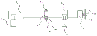
Fig. 1 is a schematic structural diagram of the present invention;
FIG. 2 is a front view of the structure of the present invention;
fig. 3 is a top view of the structure of the present invention.
The reference numbers in the figures are as follows:
1. the automatic marking device comprises a rack, 11 parts of a first guide wheel, 12 parts of a guide rail, 2 parts of a sliding block, 21 parts of a second guide wheel, 3 parts of a lead screw, 31 parts of a rotating wheel, 4 parts of a marking frame, 41 parts of a marking pen, 42 parts of a sliding part, 43 parts of a sleeve, 44 parts of a telescopic rod, 45 parts of a spring, 5 parts of a limiting body and 6 parts of a screw.
Detailed Description
The invention will be further described with reference to the following examples in the drawings.
As shown in fig. 1 to 3, the device for quickly positioning the center line of the steel pipe comprises a frame 1 and two first guide wheels 11 positioned on the frame 1, wherein the first guide wheels 11 are positioned on two sides of one end of the frame 1. The frame 1 includes guide rail 12, is equipped with the slider 2 that can move along guide rail 12 on the guide rail 12, is equipped with second leading wheel 21 on the slider 2, and the quantity of second leading wheel 21 is two and is located the slider 2 lower extreme. And moving the sliding block 2 to place the first guide wheel 11 and the second guide wheel 21 on two sides of the pipe and contact with the outer surface of the pipe, and when the device is moved along the pipe, the first guide wheel 11 and the second guide wheel 21 roll along the pipe. The first guide wheel 11 and the second guide wheel 21 can also be V-shaped structures, and the steel pipe is clamped in a V-shaped notch.
The rack 1 is provided with a lead screw 3, the lead screw 3 penetrates through the sliding block 2 and is in threaded fit with the sliding block 2, and the movable sliding block 2 of the lead screw 3 is rotated. The guide rail 12 is also provided with a marking rack 4, and the marking rack 4 is provided with a marking pen 41. The guide rail 12 is provided with scales arranged along the extension direction of the guide rail, the scale value of the center line of the steel pipe or other marking positions is judged according to the position scale value of the second guide wheel 21, the marking frame 4 is moved to the scales, the positioning device is moved along the pipe, and the marking pen 41 can mark the center line or other processing positioning lines.
The scribing frame 4 comprises a sliding part 42 capable of moving along the guide rail 12 and a sleeve 43 positioned at the side part of the sliding part 42, wherein an expansion link 44 is arranged in the sleeve 43, a spring 45 is arranged between the lower end of the expansion link 44 and the sleeve 43, and a scribing pen 41 is arranged on the expansion link 44. The sliding portion 42 is a structure surrounding the guide rail 12, and the inner wall thereof has the same sectional shape as the guide rail 12. The sleeve 43 is located on the sliding part 42 on the side remote from the frame 1, with its axis parallel to the direction of extension of the guide rail 12. The marking pen 41 is pressed to the side far away from the steel pipe, and the spring 45 is compressed to ensure the marking effect under the condition that the surface of the steel pipe is uneven.
The upper end of the sliding part 42 is provided with a screw hole, and the screw 6 passes through the screw hole and abuts against the guide rail 12. The knob screw has its end abutting against the surface of the guide rail 12 so that the sliding portion 42 is locked to the guide rail 12 to restrict relative displacement between the scribe line bracket and the guide rail 12 in the extending direction of the guide rail 12.
The frame 1 comprises two parallel guide rails 12, and the sliding block 2 is sleeved outside the guide rails 12 to prevent the sliding block 2 from rotating relative to the guide rails 12 along the circumferential direction of the guide rails 12. One end of the guide rail 12 is provided with a limiting body 5, and the screw rod 3 horizontally penetrates through the limiting body 5. The limiting body 5 can be fixed at the end part of the guide rail 12 through a screw, and the screw rod 3 and the sliding block 2 can be taken down after the limiting body 5 is disassembled. The end of the screw rod 3 is provided with a rotating wheel 31, the rotating wheel 31 is coaxial with the screw rod 3, and the rotating wheel 31 is provided with a handle which is held by hand to rotate the rotating wheel 31.
The first guide wheel 11 and the second guide wheel 21 comprise polytetrafluoroethylene coatings on the outer sides, the polytetrafluoroethylene coatings can rotate along a rotating shaft fixed on the frame 2 or the sliding block 2, and the polytetrafluoroethylene coatings have certain elasticity and self-lubricating property and can adapt to the rough and uneven conditions which may occur on the outer surface of the pipe.
The above description is only for explaining the present invention, so that the person skilled in the art can completely implement the present invention, but not for limiting the present invention, and after reading the present specification, the person skilled in the art can make modifications to the present embodiment as required without inventive contribution, which are all modifications without inventive contribution, but are protected by patent laws within the scope of the claims of the present invention.
Claims (8)
1. The utility model provides a quick positioner of steel pipe central line which characterized in that: including frame (1) and being located first leading wheel (11) in frame (1), frame (1) includes guide rail (12), be equipped with on guide rail (12) and follow slider (2) that guide rail (12) removed, be equipped with second leading wheel (21) on slider (2), be provided with lead screw (3) on frame (1), lead screw (3) pass slider (2) and with slider (2) screw-thread fit, still be provided with on guide rail (12) and mark line frame (4), be equipped with on mark line frame (4) and mark line pen (41).
2. The steel pipe center line quick positioning device of claim 1, characterized in that: the marking rack (4) comprises a sliding part (42) capable of moving along the guide rail (12) and a sleeve (43) located on the side of the sliding part (42), an expansion rod (44) is arranged in the sleeve (43), a spring (45) is arranged between the lower end of the expansion rod (44) and the sleeve (43), and the marking pen (41) is arranged on the expansion rod (44).
3. The steel pipe center line quick positioning device of claim 2, characterized in that: the sliding part (42) is provided with a screw hole, and a screw (6) penetrates through the screw hole and is abutted to the guide rail (12).
4. The steel pipe center line quick positioning device of claim 1, characterized in that: the machine frame (1) comprises two parallel guide rails (12), and the sliding blocks (2) are sleeved on the guide rails (12).
5. The steel pipe center line quick positioning device of claim 4, wherein: and one end of the guide rail (12) is provided with a limiting body (5), and the lead screw (3) penetrates through the limiting body (5).
6. The steel pipe center line quick positioning device of claim 1, characterized in that: and a rotating wheel (31) is arranged at the end part of the lead screw (3).
7. The steel pipe center line quick positioning device of claim 1, characterized in that: the number of the first guide wheels (11) and the number of the second guide wheels (21) are both two.
8. The steel pipe center line quick positioning device of claim 1, characterized in that: the first guide wheel (11) and the second guide wheel (21) comprise polytetrafluoroethylene coatings positioned on the outer sides.
Priority Applications (1)
| Application Number | Priority Date | Filing Date | Title |
|---|---|---|---|
| CN202020258327.XU CN211916804U (en) | 2020-03-05 | 2020-03-05 | Steel pipe central line quick positioning device |
Applications Claiming Priority (1)
| Application Number | Priority Date | Filing Date | Title |
|---|---|---|---|
| CN202020258327.XU CN211916804U (en) | 2020-03-05 | 2020-03-05 | Steel pipe central line quick positioning device |
Publications (1)
| Publication Number | Publication Date |
|---|---|
| CN211916804U true CN211916804U (en) | 2020-11-13 |
Family
ID=73346435
Family Applications (1)
| Application Number | Title | Priority Date | Filing Date |
|---|---|---|---|
| CN202020258327.XU Withdrawn - After Issue CN211916804U (en) | 2020-03-05 | 2020-03-05 | Steel pipe central line quick positioning device |
Country Status (1)
| Country | Link |
|---|---|
| CN (1) | CN211916804U (en) |
Cited By (3)
| Publication number | Priority date | Publication date | Assignee | Title |
|---|---|---|---|---|
| CN112548631A (en) * | 2021-01-07 | 2021-03-26 | 义乌市燕荔贸易有限公司 | Multi-pipe-diameter pipeline rapid drilling equipment |
| CN112706146A (en) * | 2020-12-23 | 2021-04-27 | 苏州震伴威自动化设备科技有限公司 | Be applied to central line marking device of steel |
| CN114714316A (en) * | 2022-06-08 | 2022-07-08 | 徐州翔宇印务有限公司 | Automatic accurate cutting and scribing device and process for wooden furniture |
-
2020
- 2020-03-05 CN CN202020258327.XU patent/CN211916804U/en not_active Withdrawn - After Issue
Cited By (5)
| Publication number | Priority date | Publication date | Assignee | Title |
|---|---|---|---|---|
| CN112706146A (en) * | 2020-12-23 | 2021-04-27 | 苏州震伴威自动化设备科技有限公司 | Be applied to central line marking device of steel |
| CN112548631A (en) * | 2021-01-07 | 2021-03-26 | 义乌市燕荔贸易有限公司 | Multi-pipe-diameter pipeline rapid drilling equipment |
| CN112548631B (en) * | 2021-01-07 | 2022-10-04 | 义乌市燕荔贸易有限公司 | Multi-pipe-diameter pipeline rapid drilling equipment |
| CN114714316A (en) * | 2022-06-08 | 2022-07-08 | 徐州翔宇印务有限公司 | Automatic accurate cutting and scribing device and process for wooden furniture |
| CN114714316B (en) * | 2022-06-08 | 2022-09-02 | 徐州翔宇印务有限公司 | Automatic and accurate cutting and scribing device and process for wooden furniture |
Similar Documents
| Publication | Publication Date | Title |
|---|---|---|
| CN211916804U (en) | Steel pipe central line quick positioning device | |
| CN102445128B (en) | Mechanism for quickly withdrawing detection pin | |
| CN207132827U (en) | A kind of bearing roller detection means | |
| CN111571554A (en) | Equidistant marking device for metal plate | |
| CN203658283U (en) | Sapphire ingot detection device | |
| CN203993865U (en) | A kind of arbitrarily angled pipe communicated wire chalker | |
| CN213165360U (en) | Marking device of culture lithography apparatus | |
| CN201109112Y (en) | Positioning marking tool for major diameter arc | |
| CN210081715U (en) | Panel marking off processingequipment | |
| CN203615852U (en) | Intermediate diameter runout detection device used for precise screw rod | |
| CN203837615U (en) | Centering special detecting fixture for belt pulley | |
| CN217637146U (en) | Hydraulic cylinder body circular hole inner diameter cylindricity measuring device | |
| CN110497371B (en) | Perpendicular pipeline scriber | |
| CN112247945B (en) | Multifunctional test pipe pretreatment operation platform | |
| CN205572001U (en) | High -efficient cantilever type aligning device of support body class part | |
| CN204868832U (en) | Plane circular arc marking tool | |
| CN208713445U (en) | Clamped one time processes the tooling in three faces | |
| CN219854560U (en) | Part machining center positioner | |
| CN207923067U (en) | A kind of axial workpiece detection device | |
| CN218557073U (en) | Scribing and shape-taking tool for circular tube intersecting piece | |
| CN206504697U (en) | Thrust conical bearing raceway angles measuring instrument | |
| CN217097649U (en) | Adjustable V-shaped positioning block | |
| CN216177110U (en) | Pipeline cutting device | |
| CN214235733U (en) | Automatic pipe bender | |
| CN219190574U (en) | Marking tool for furniture processing |
Legal Events
| Date | Code | Title | Description |
|---|---|---|---|
| GR01 | Patent grant | ||
| GR01 | Patent grant | ||
| AV01 | Patent right actively abandoned | ||
| AV01 | Patent right actively abandoned | ||
| AV01 | Patent right actively abandoned |
Granted publication date: 20201113 Effective date of abandoning: 20240228 |
|
| AV01 | Patent right actively abandoned |
Granted publication date: 20201113 Effective date of abandoning: 20240228 |