CN211916195U - Lathe foundry goods fluting anchor clamps - Google Patents
Lathe foundry goods fluting anchor clamps Download PDFInfo
- Publication number
- CN211916195U CN211916195U CN202020579666.8U CN202020579666U CN211916195U CN 211916195 U CN211916195 U CN 211916195U CN 202020579666 U CN202020579666 U CN 202020579666U CN 211916195 U CN211916195 U CN 211916195U
- Authority
- CN
- China
- Prior art keywords
- casting
- groove
- frame body
- base
- plate
- Prior art date
- Legal status (The legal status is an assumption and is not a legal conclusion. Google has not performed a legal analysis and makes no representation as to the accuracy of the status listed.)
- Active
Links
Images


Landscapes
- Machine Tool Units (AREA)
Abstract
The utility model discloses a slotting fixture for machine tool castings; the method comprises the following steps: the middle part of the base is provided with a first through groove, the bottom of the base is in contact with the working surface and is tightly pressed with the working surface through at least two first pressing pieces, the first through groove is used for accommodating the frame body casting, and the frame body casting is inverted in the first through groove; the at least four elastic pressing pieces are symmetrically arranged on the side wall of the base at intervals, and one end of each elastic pressing piece is arranged in the first through groove and presses the side wall of the frame body casting; the plurality of compression bolts are symmetrically connected to the side wall of the base at intervals and used for jacking the side wall of the frame body casting to adjust the levelness of the upper surface of the frame body casting; therefore, the technical problem that positioning is inconvenient when the V-shaped groove is machined on the tail frame of the machine tool casting is solved, and the technical effects that positioning can be reliably realized and operation is relatively convenient are achieved.
Description
Technical Field
The utility model relates to a lathe technical field, specific lathe foundry goods fluting anchor clamps that says so.
Background
There are many kinds of machine tools, such as a normal horizontal lathe, a numerical control milling machine, a boring machine, a vertical lathe, and the like; the common horizontal lathe or the numerical control horizontal lathe generally has a tail stock, for example, the chinese patent application No. 201020507750.5, the patent subject name is the prior art of the lathe capable of moving the tail stock of the lathe in a labor-saving manner, and the tail stock moves along a track on the lathe through a V-shaped groove at the bottom;
the tail frame generally comprises a frame body, the bottom of the tail frame is provided with two V-shaped grooves and a thimble connected to the frame body; during processing and manufacturing, a frame body is generally cast into a casting by adopting a mold, and then machining is carried out; because the shape of the frame body is complex and irregular, the positioning is inconvenient when the V-shaped groove is processed.
SUMMERY OF THE UTILITY MODEL
For solving not enough among the prior art, the utility model provides a lathe foundry goods fluting anchor clamps to solve among the correlation technique to lathe foundry goods tailstock, during processing V-arrangement recess, fix a position inconvenient technical problem.
The utility model discloses a realize above-mentioned purpose, realize through following technical scheme: a machine tool casting grooving jig; the method comprises the following steps: the base is provided with a first through groove in the middle, the bottom of the base is in contact with a working surface and is pressed against the working surface through at least two first pressing pieces, the first through groove is used for accommodating frame castings, and the frame castings are inverted in the first through groove;
the at least four elastic pressing pieces are symmetrically arranged on the side wall of the base at intervals, and one ends of the elastic pressing pieces are arranged in the first through grooves and press the side wall of the frame body casting;
and the plurality of compression bolts are symmetrically connected to the side wall of the base at intervals and used for jacking the side wall of the frame body casting to adjust the levelness of the upper surface of the frame body casting.
Further: the base includes: the bottom plate is pressed on the working surface by the first pressing piece; the bottom of the supporting plate is connected to the bottom plate, and the middle part of the supporting plate is provided with the first through groove; and at least six reinforcing ribs which are symmetrically connected between the bottom plate and the supporting plate at intervals.
Further: the bottom plate is of a cuboid structure.
Further: the layer board is bending structure, includes: the first bending plate is of an inverted cone-shaped cross section appearance and is used for connecting the elastic pressing piece, and the inner wall of the first bending plate is in clearance fit with the frame body casting; and the two vertical plates are symmetrically connected to the top of the first bending plate and used for being connected with the compression bolts, the inner wall of each vertical plate is in clearance fit with the frame body casting, and the upper surfaces of the vertical plates are lower than the upper surface of the frame body casting.
Further: the elastic pressing member includes: one end of the central shaft is provided with an external thread section which passes through the first through hole on the side wall of the base; the pressing plate is arranged in the first through groove, connected to the other end of the central shaft and contacted with the side wall of the frame body casting; the spring is arranged in the first through groove and sleeved on the central shaft, one end of the spring is attached to the inner wall of the base, and the other end of the spring is attached to the pressing plate; and the locking nut is arranged outside the first through groove, connected to the external thread section on the central shaft and used for compressing the spring.
Further: further comprising: and the at least two second pressing pieces are connected to the working surface and press the frame body casting.
Contrast correlation technique, the beneficial effects of the utility model reside in that: a slotting clamp for a machine tool casting is provided with a base, wherein the base is connected to a working surface of processing equipment, such as a working surface of a milling machine, and a first through groove is formed in the middle of the base and can accommodate a frame casting; the base is provided with an elastic pressing piece and a pressing bolt; when the frame body casting is placed in the first through groove in an inverted mode, the elastic pressing piece is pushed open, the elastic pressing piece is compressed and then clings to the side wall of the frame body casting, one end of the frame body casting is limited, the pressing bolt is adjusted, the pressing bolt on one side starts to adjust, the pressing bolt is continuously rotated, the pressing bolt pushes the frame body casting, the upper surface of the frame body casting is gradually in a horizontal state, the pressing bolt on the other side is adjusted again, the pressing bolt on the two sides is continuously adjusted, the levelness of the upper surface of the frame body casting meets the requirement, the upper surface is processed to form a V-shaped groove, and positioning and operation are relatively convenient; therefore, the technical problem that the positioning is inconvenient when the V-shaped groove is machined on the tail frame of the machine tool casting is solved, the technical effects that the positioning can be reliably realized and the operation is relatively convenient are achieved, and the machine tool casting tail frame positioning device has practicability.
Drawings
FIG. 1 is a schematic diagram of a three-dimensional assembly structure in an actual use state;
FIG. 2 is a front view of FIG. 1;
FIG. 3 is a partial cross-sectional view of FIG. 1;
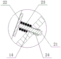
fig. 4 is a partially enlarged schematic view of a portion a in fig. 3;
FIG. 5 is a schematic view of a three-dimensional assembly structure of a base, an elastic pressing member and a pressing bolt;
FIG. 6 is a partial cross-sectional view of FIG. 5;
FIG. 7 is a schematic view of a three-dimensional final assembly structure with the addition of a second compression element;
reference numerals shown in the drawings: 10. the frame casting comprises a base, 11 parts, a bottom plate, 12 parts, a supporting plate, 121 parts, a first bending plate, 122 parts, a vertical plate, 13 parts, a reinforcing rib, 14 parts, a first through hole, 15 parts, a first through groove, 20 parts, an elastic pressing piece, 21 parts, a central shaft, 22 parts, a pressing plate, 23 parts, a spring, 24 parts, a locking nut, 30 parts, a compression bolt, 40 parts, a second pressing piece, 100 parts, a first pressing piece and 200 parts.
Detailed Description
The technical solutions in the embodiments will be described clearly and completely with reference to the drawings in the embodiments, and it is obvious that the described embodiments are only a part of the embodiments, not all of the embodiments;
a slotting clamp for a machine tool casting solves the technical problem that when a V-shaped groove is machined on a tail frame of the machine tool casting in the related technology, positioning is inconvenient; the positioning device can be manufactured and used, and achieves the positive effects of reliably realizing positioning and relatively conveniently operating; the general idea is as follows:
one embodiment is as follows:
see fig. 1, 2, 3; a machine tool casting grooving jig; the method comprises the following steps:
a base 10, which has a first through groove 15 in the middle, contacts the bottom of the base with the working surface and is pressed against the working surface by at least two first pressing pieces 100, wherein the first through groove 15 is used for accommodating the frame casting 200, and the frame casting 200 is inverted in the first through groove 15;
at least four elastic pressing pieces 20 symmetrically spaced on the side wall of the base 10, and having one end disposed in the first through groove 15 to press the side wall of the frame casting 200;
the plurality of compression bolts 30 are symmetrically connected to the side wall of the base 10 at intervals and used for jacking the side wall of the frame casting 200 and adjusting the levelness of the upper surface of the frame casting 200;
specifically, in implementation, a base 10 is provided and connected to a working surface of a processing device, such as a working surface of a milling machine, and a first through groove 15 is formed in the middle of the base 10 and can accommodate the frame casting 200; the base 10 is provided with an elastic pressing piece 20 and a pressing bolt 30; when the frame casting 200 is placed in the first through groove 15 in an inverted manner, the elastic pressing piece 20 is pushed open, the elastic pressing piece 20 is compressed and then clings to the side wall of the frame casting 200, one end of the frame casting 200 is limited, the pressing bolt 30 is adjusted, the pressing bolt 30 on one side starts to be adjusted, the pressing bolt 30 is continuously rotated, the pressing bolt 30 pushes the frame casting 200, the upper surface of the frame casting 200 is gradually in a horizontal state, the pressing bolt 30 on the other side is adjusted, the levelness of the upper surface of the frame casting 200 meets the requirement through the pressing bolts 30 on the two sides, the upper surface is processed to form the V-shaped groove 201, and positioning and operation are relatively convenient; therefore, the technical problem that the positioning is inconvenient when the V-shaped groove 201 is machined on the tail frame of the machine tool casting is solved, and the technical effects that the positioning can be reliably realized and the operation is relatively convenient are achieved;
in another embodiment:
see fig. 1, fig. 2, fig. 3, fig. 5, fig. 6; in practice, the base 10 comprises: a base plate 11 pressed against the work surface by the first presser 100; the bottom of the supporting plate 12 is connected to the bottom plate 11, and the middle part of the supporting plate is provided with the first through groove 15; six reinforcing ribs 13 are symmetrically connected between the bottom plate 11 and the supporting plate 12 at intervals; the bottom plate 11 is of a cuboid structure; the supporting plate 12 is of a bending structure and comprises: a first bending plate 121 having a cross-sectional shape of an inverted cone structure for connecting the elastic pressing member 20, and having an inner wall in clearance fit with the frame casting 200; and two vertical plates 122 symmetrically connected to the top of the first bending plate 121 for connecting the pressing bolt 30, the inner walls of which are in clearance fit with the frame casting 200, and the upper surfaces of the vertical plates 122 are lower than the upper surface of the frame casting 200;
the bottom plate 11, the supporting plate 12 and the reinforcing ribs 13 are integrally cast into a blank or are formed by assembly welding, and a first through groove 15 is formed in the middle part and used for accommodating the frame body casting 200, so that the frame body casting 200 can be smoothly placed into the first through groove 15, tightly attached to the elastic pressing part 20 and tightly pressed by the compression bolt 30;
the first bending plate 121 is arranged, the cross section of the first bending plate is in an inverted cone structure, so that the elastic pressing piece 20 is in an inclined state, the included angle between the center line of the elastic pressing piece 20 and the horizontal plane is 60 degrees, when the frame casting 200 pushes the elastic pressing piece 20, the elastic pressing piece 20 can be smoothly compressed, and one end of the frame casting 200 is clamped by the elastic pressing piece 20;
the vertical plate 122 is arranged and is in a vertical state with the working surface, so that a threaded through hole is favorably machined in the vertical plate 122, the compression bolt 30 is smoothly rotated after the compression bolt 30 is in threaded connection with the threaded through hole, and meanwhile, the compression bolt 30 and the vertical plate 122 are in a vertical state, so that the frame body casting 200 is more favorably pushed, and the upper surface of the frame body casting 200 gradually tends to be horizontal;
in another embodiment:
see fig. 1, fig. 2, fig. 3, fig. 4, fig. 5, fig. 6; in practice, the spring follower 20 comprises: a central shaft 21, one end of which is provided with an external thread section, and the central shaft passes through the first through hole 14 on the side wall of the base 10; a pressing plate 22 disposed inside the first through groove 15, connected to the other end of the central shaft 21, and contacting the sidewall of the frame casting 200; the spring 23 is arranged in the first through groove 15, is sleeved on the central shaft 21, and has one end attached to the inner wall of the base 10 and the other end attached to the pressing plate 22; and a lock nut 24 disposed outside the first through slot 15 and connected to the external thread section of the central shaft 21 for compressing the spring 23;
the central shaft 21 is a section of circular shaft, one end of the central shaft is provided with an external thread section, and the central shaft penetrates through the first through hole 14 and is in clearance fit with the first through hole 14; the pressing plate 22 is square in shape and is welded with the other end of the central shaft 21; the spring 23 is a cylindrical spring in the prior art, one end of the spring is closely matched with the inner wall of the first bending plate 121, and the other end of the spring is closely matched with the pressing plate 22; after the locking nut 24 is connected with the external thread section on the central shaft 21, the spring 23 is in a micro-compression state, and one end of the locking nut 24 is closely matched with the outer wall of the first bending plate 121 to form a stop; the frame casting 200 has a large self-weight, when the frame casting is placed in the first through groove 15, the pressing plate 22 can be pushed, the pressing plate 22, the central shaft 21 and the locking nut 24 slide along the first through hole 14, the spring 23 continues to be compressed, the frame casting 200 is pressed by the elastic force generated by the spring 23, and one end of the frame casting 200 is positioned;
in another embodiment:
see fig. 1, 2, 5; when the device is implemented, the compression bolt 30 adopts an inner hexagon bolt, and when the compression bolt is rotated, an inner hexagon wrench is adopted for operation, so that the operation is more convenient;
in another embodiment:
see fig. 1, 2, 3; the first presser 100 and the frame casting 200 are both of prior art construction; the first follower 100 includes: the T-shaped nut is inserted into the T-shaped slot on the working surface; the threaded column is provided with external threads, one end of the threaded column is connected to the T-shaped nut in a threaded mode, and the other end of the threaded column penetrates through the T-shaped slot; the pressing block is sleeved on the threaded column through the second through hole, and one end of the pressing block presses the upper surface of the bottom plate 11; the bottom of the cushion block is in contact with the working surface, and the top of the cushion block supports the other end of the pressing block; the hexagonal nut is connected to the threaded column and used for pressing the pressing block; those skilled in the art, having the benefit of this disclosure, will be able to ascertain directly and unambiguously how to arrange them without undue experimentation and without creative effort;
in another embodiment:
see FIG. 7; when in implementation, the method further comprises the following steps: at least two second pressing members 40 connected to the working surface for pressing the frame casting 200; the second pressing piece 40 has the same structure as the first pressing piece 100, and after the frame casting 200 is pressed, the positioning reliability of the frame casting 200 is better;
in another embodiment:
see FIG. 1; during implementation, the number of the V-shaped grooves 201 on at least one frame casting 200 can be processed at each time, is not limited to one, the length of the base 10 can be properly increased according to the specification of the processing equipment, the number of the elastic pressing pieces 20 and the compression bolts 30 can be increased, a plurality of frame castings 200, such as two, three, four and the like, can be continuously arranged in the first through groove 15, and after the positions are adjusted, the V-shaped grooves 201 are simultaneously processed, so that the working efficiency is relatively high;
the working principle is as follows: in implementation, a base 10 is provided and connected to a working surface of a processing device, such as a milling machine, and a first through groove 15 is formed in the middle of the base 10 and can accommodate the frame casting 200; the base 10 is provided with an elastic pressing piece 20 and a pressing bolt 30; when the frame casting 200 is placed in the first through groove 15 in an inverted mode, the elastic pressing piece 20 is pushed open, the elastic pressing piece 20 is compressed and then clings to the side wall of the frame casting 200, one end of the frame casting 200 is limited, the pressing bolt 30 is adjusted, the pressing bolt 30 on one side starts to adjust, the pressing bolt 30 continuously rotates, the pressing bolt 30 pushes the frame casting 200, the upper surface of the frame casting 200 is gradually in a horizontal state, the pressing bolt 30 on the other side is adjusted, the pressing bolts 30 on the two sides are adjusted continuously, the levelness of the upper surface of the frame casting 200 meets requirements, the upper surface is processed, the V-shaped groove 201 is formed, and positioning and operation are relatively convenient.
In the description, it is to be understood that the terms "upper", "lower", "left", "right", "front", "rear", and the like indicate orientations or positional relationships based on the positional relationships illustrated in the drawings, and are only for convenience of description or simplicity of description, but do not indicate specific orientations that are necessary; the operation processes described in the embodiments are not absolute use steps, and may be adjusted accordingly when actually used.
Unless defined otherwise, technical or scientific terms used herein shall have the ordinary meaning as understood by one of ordinary skill in the art; the use of "first," "second," and the like in the description and in the claims does not denote any order, quantity, or importance, but rather the terms "a" and "an" and the like are used to distinguish one element from another, and likewise, are not intended to denote an absolute limitation of quantity, but rather denote the presence of at least one, as may be determined by reference to the example.
The above description is only for the preferred embodiment, but the scope of protection is not limited thereto, and any person skilled in the art should be covered by the protection scope, which is equivalent to or changed from the technical solution and the utility model concept disclosed in the present disclosure.
Claims (6)
1. The utility model provides a lathe foundry goods fluting anchor clamps which characterized in that includes:
a base (10), the middle part of which is provided with a first through groove (15), the bottom of which is contacted with a working surface and is pressed against the working surface through at least two first pressing pieces (100), the first through groove (15) is used for accommodating the frame body casting (200), and the frame body casting (200) is inverted in the first through groove (15);
at least four elastic pressing pieces (20) symmetrically and alternately penetrating through the side wall of the base (10), and one end of each elastic pressing piece is arranged in the first through groove (15) and presses the side wall of the frame casting (200);
and the plurality of compression bolts (30) are symmetrically connected to the side wall of the base (10) at intervals and used for jacking the side wall of the frame body casting (200) and adjusting the levelness of the upper surface of the frame body casting (200).
2. The machine tool casting grooving jig of claim 1, wherein: the base (10) comprises: a base plate (11) pressed against the work surface by the first pressing member (100); the bottom of the supporting plate (12) is connected to the bottom plate (11), and the middle part of the supporting plate is provided with the first through groove (15); and at least six reinforcing ribs (13) which are symmetrically connected between the bottom plate (11) and the supporting plate (12) at intervals.
3. The machine tool casting grooving jig of claim 2, wherein: the bottom plate (11) is of a cuboid structure.
4. The machine tool casting grooving jig of claim 3, wherein: the supporting plate (12) is of a bending structure and comprises: the first bending plate (121) is of an inverted cone-shaped cross section, is used for connecting the elastic pressing piece (20), and has an inner wall in clearance fit with the frame body casting (200); and two vertical plates (122) symmetrically connected to the top of the first bending plate (121) for connecting the pressing bolt (30), the inner wall of the vertical plate is in clearance fit with the frame body casting (200), and the upper surface of the vertical plate (122) is lower than that of the frame body casting (200).
5. The machine tool casting grooving jig of claim 1, wherein: the elastic pressing member (20) includes: a central shaft (21) with an external thread section at one end, which passes through a first through hole (14) on the side wall of the base (10); the pressing plate (22) is arranged inside the first through groove (15), is connected to the other end of the central shaft (21) and is in contact with the side wall of the frame body casting (200); the spring (23) is arranged in the first through groove (15) and sleeved on the central shaft (21), one end of the spring is attached to the inner wall of the base (10), and the other end of the spring is attached to the pressing plate (22); and a locking nut (24) arranged outside the first through groove (15) and connected to the external thread section on the central shaft (21) for compressing the spring (23).
6. The machine tool casting grooving jig of claim 1, wherein: further comprising: and at least two second pressing pieces (40) connected to the working surface and pressing the frame casting (200).
Priority Applications (1)
| Application Number | Priority Date | Filing Date | Title |
|---|---|---|---|
| CN202020579666.8U CN211916195U (en) | 2020-04-17 | 2020-04-17 | Lathe foundry goods fluting anchor clamps |
Applications Claiming Priority (1)
| Application Number | Priority Date | Filing Date | Title |
|---|---|---|---|
| CN202020579666.8U CN211916195U (en) | 2020-04-17 | 2020-04-17 | Lathe foundry goods fluting anchor clamps |
Publications (1)
| Publication Number | Publication Date |
|---|---|
| CN211916195U true CN211916195U (en) | 2020-11-13 |
Family
ID=73328409
Family Applications (1)
| Application Number | Title | Priority Date | Filing Date |
|---|---|---|---|
| CN202020579666.8U Active CN211916195U (en) | 2020-04-17 | 2020-04-17 | Lathe foundry goods fluting anchor clamps |
Country Status (1)
| Country | Link |
|---|---|
| CN (1) | CN211916195U (en) |
Cited By (1)
| Publication number | Priority date | Publication date | Assignee | Title |
|---|---|---|---|---|
| CN113732750A (en) * | 2021-08-27 | 2021-12-03 | 沈阳鼓风机集团核电泵业有限公司 | Frock clamp and processing subassembly |
-
2020
- 2020-04-17 CN CN202020579666.8U patent/CN211916195U/en active Active
Cited By (1)
| Publication number | Priority date | Publication date | Assignee | Title |
|---|---|---|---|---|
| CN113732750A (en) * | 2021-08-27 | 2021-12-03 | 沈阳鼓风机集团核电泵业有限公司 | Frock clamp and processing subassembly |
Similar Documents
| Publication | Publication Date | Title |
|---|---|---|
| CN211916195U (en) | Lathe foundry goods fluting anchor clamps | |
| CN215919787U (en) | Shell clamp structure and vertical machining center | |
| CN212552786U (en) | Fixture tool of machine tool machining center | |
| CN2803612Y (en) | Positioned gripping jaw base assembly | |
| CN213917091U (en) | Mechanical fixture with rotary clamping pull-down device | |
| CN113977328A (en) | Tank track movable support technological equipment system | |
| CN209737092U (en) | special fixture for milling dovetail groove on workpiece | |
| CN218363337U (en) | Inner hole compressing clamp | |
| CN218873955U (en) | Combined pressing plate and broaching machine clamp | |
| CN215281001U (en) | Inclined clamping type workpiece machining clamp | |
| CN215239312U (en) | General forked tail anchor clamps that use on five machining centers | |
| CN216398740U (en) | Tool clamp for cylindrical workpiece | |
| CN220533031U (en) | Frock clamp in counter sinking hole in dysmorphism part processing inclined plane | |
| CN218533635U (en) | Automobile model clamping device | |
| CN217122493U (en) | Special fixture for milling machine | |
| CN117506504B (en) | Tool clamp for machining precise die parts by milling machine tool | |
| CN216264714U (en) | Novel precise five-axis machine tool combined clamp | |
| CN221792248U (en) | Novel aperture honing device | |
| CN214444654U (en) | Three-axis suspension type clamp | |
| CN219945334U (en) | Multi-axis machining tool for columnar thin-wall part with multiple space angles | |
| CN215357350U (en) | Adjustable clamp for shaft part machining combination | |
| CN212265238U (en) | Clamp for machining oblique oil hole of valve body by machine tool | |
| CN214264705U (en) | Positioning equipment suitable for automatic lathe turning of inclined plane work piece | |
| CN213469695U (en) | Clamp for processing hole of support plate of automobile battery valve | |
| CN218776136U (en) | Five-axis machining clamp for artificial joint comparison block |
Legal Events
| Date | Code | Title | Description |
|---|---|---|---|
| GR01 | Patent grant | ||
| GR01 | Patent grant |