CN211904074U - Quick switching automobile testing fixture positioning mechanism - Google Patents
Quick switching automobile testing fixture positioning mechanism Download PDFInfo
- Publication number
- CN211904074U CN211904074U CN202020857391.XU CN202020857391U CN211904074U CN 211904074 U CN211904074 U CN 211904074U CN 202020857391 U CN202020857391 U CN 202020857391U CN 211904074 U CN211904074 U CN 211904074U
- Authority
- CN
- China
- Prior art keywords
- fixed
- positioning mechanism
- mount pad
- bottom plate
- mounting
- Prior art date
- Legal status (The legal status is an assumption and is not a legal conclusion. Google has not performed a legal analysis and makes no representation as to the accuracy of the status listed.)
- Expired - Fee Related
Links
Images

Landscapes
- A Measuring Device Byusing Mechanical Method (AREA)
Abstract
The utility model discloses a utensil positioning mechanism is examined to fast switch over's automobile relates to the detection device field, and it includes the bottom plate, the top of bottom plate is fixed with the installation cover, and installs the inboard fixed column that runs through on the bottom plate that is fixed in of cover, and the upper end of fixed column is fixed with the objective table, the installation is covered and is rotated and install the rotating tube of suit in the fixed column outside, and the lower extreme of rotating tube is fixed with the ring gear of suit in the fixed column outside, be fixed with driving motor on the bottom plate, driving motor's output is fixed with the gear with ring gear meshing. The utility model discloses not only can be used for installing current detection main part when needing, the convenience detects the part, and can be quick switch to the different sides of part, and then make the detection convenient, and rotate the rolling disc through the manpower and can adjust the detection height, and the mount pad that sets up can rotate, and then can angle regulation when needing to conveniently fix a position.
Description
Technical Field
The utility model relates to a detection device field especially relates to a quick switching's automotive checking fixture positioning mechanism.
Background
The gauge is a simple tool for controlling various sizes (such as pore diameter, space size and the like) of products by industrial production enterprises, improves production efficiency and control quality, is suitable for products produced in large scale, such as automobile parts, to replace professional measuring tools, such as smooth plug gauges, threaded plug gauges, outer diameter snap gauges and the like. However, the existing positioning mechanism of the automobile checking fixture has the defects of complex measurement operation, incapability of quickly switching the detection position, small application range, inconvenience in use and incapability of conveniently adjusting the height and angle of the detection main body, and therefore needs to be improved.
SUMMERY OF THE UTILITY MODEL
The utility model aims at solving the shortcoming that exists among the prior art, and the automotive checking fixture positioning mechanism who provides a fast switch over.
In order to achieve the above purpose, the utility model adopts the following technical scheme:
a fast-switching automobile checking fixture positioning mechanism comprises a bottom plate, wherein a mounting cover is fixed to the top of the bottom plate, a fixing column fixed to the bottom plate penetrates through the inner side of the mounting cover, an object stage is fixed to the upper end of the fixing column, a rotating pipe sleeved on the outer side of the fixing column is rotatably mounted on the mounting cover, a gear ring sleeved on the outer side of the fixing column is fixed to the lower end of the rotating pipe, a driving motor is fixed to the bottom plate, and a gear meshed with the gear ring is fixed to the output end of the driving motor;
the upper end of the rotating tube is fixed with an installation platform sleeved outside the fixed column, the installation platform is provided with a detachable hollow installation seat with two open ends, the top of the hollow installation seat is fixed with a vertical installation box, the hollow installation seat is rotatably provided with a threaded rod with the upper end rotatably connected with the top wall of the installation box, the lower end of the threaded rod is fixed with a rotating disc positioned inside the hollow installation seat, the threaded rod is sleeved with a vertically movable fixed block which is in sliding fit in the installation box in a sleeved mode through threads, and the other end of the fixed block is rotatably connected with the installation seat through a bolt.
Preferably, the diameter of the rotating disc is larger than the transverse width of the hollow mounting seat, and the diameter of the rotating disc is smaller than the longitudinal length of the hollow mounting seat.
Preferably, the hollow mounting seat is in threaded connection with a locking screw, and the lower end of the locking screw is in contact with the top surface of the rotating disc.
Preferably, one side of the installation box, which is close to the installation seat, is provided with a vertical sliding groove, the fixed block is in sliding fit in the sliding groove, and the fixed block is rectangular.
Preferably, the mounting cover is provided with a mounting hole matched with the rotating pipe, and the rotating pipe is rotatably mounted in the mounting hole through a bearing.
Preferably, a controller and a power supply are fixed on the front side of the mounting cover, and the output end of the controller is electrically connected with the driving motor.
Preferably, both ends of the mounting table are provided with jacks, and insertion rods with upper ends fixed with the hollow mounting seat are inserted in the jacks.
The utility model discloses a mount pad, driving motor, the gear, the ring gear, the rotating tube, the mount table, the rolling disc, the cavity mount pad, the setting of threaded rod and fixed block, not only can be used for installing current detection main part when needs, conveniently detect the part, and the different sides of switching to the part that can be quick, and then make and detect the convenience, and rotate the rolling disc through the manpower and can adjust the detection height, and the mount pad that sets up can rotate, and then can adjust the angle when needs, thereby conveniently fix a position, and the operation is thus simple, whole mechanism structure, and the cost of manufacture is low.
Drawings
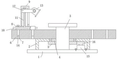
Fig. 1 is a schematic structural diagram of the present invention.
Fig. 2 is a front view of the present invention.
Reference numbers in the figures: the device comprises a base plate 1, a mounting cover 2, a fixing column 3, a rotating tube 4, a gear ring 5, a mounting table 6, a jack 7, a hollow mounting seat 8, a mounting box 9, a rotating disc 10, a threaded rod 11, a fixing block 12, a mounting seat 13, an inserted rod 14, a driving motor 15 and a gear 16.
Detailed Description
The technical solutions in the embodiments of the present invention will be described clearly and completely with reference to the accompanying drawings in the embodiments of the present invention, and it is obvious that the described embodiments are only some embodiments of the present invention, not all embodiments.
Referring to fig. 1-2, a fast switching positioning mechanism of an automobile checking fixture comprises a bottom plate 1, wherein a mounting cover 2 is fixed at the top of the bottom plate 1, a fixed column 3 fixed on the bottom plate 1 penetrates through the inner side of the mounting cover 2, an object stage is fixed at the upper end of the fixed column 3, a rotating pipe 4 sleeved on the outer side of the fixed column 3 is rotatably installed on the mounting cover 2, a gear ring 5 sleeved on the outer side of the fixed column 3 is fixed at the lower end of the rotating pipe 4, a driving motor 15 is fixed on the bottom plate 1, and a gear 16 meshed with the gear ring 5 is fixed at the output end of the driving motor 15;
the upper end of rotating tube 4 is fixed with suit in the mount table 6 in the fixed column 3 outside, and install detachable both ends open-ended cavity mount pad 8 on the mount table 6, the top of cavity mount pad 8 is fixed with vertical install bin 9, it rotates the threaded rod 11 of installing upper end and install bin 9 roof rotation connection to rotate on the cavity mount pad 8, the lower extreme of threaded rod 11 is fixed with and is located the inboard rolling disc 10 of cavity mount pad 8, but threaded sleeve joint has the vertical removal's of sliding fit in install bin 9 fixed block 12 on the threaded rod 11, the other end of fixed block 12 is connected with mount pad 13 through the bolt rotation.
In this embodiment, the diameter of rolling disc 10 is greater than the horizontal width of cavity mount pad 8, and the diameter of rolling disc 10 is less than the longitudinal length of cavity mount pad 8, threaded connection has locking screw on the cavity mount pad 8, and the lower extreme of locking screw contacts in the top surface of rolling disc 10, one side that install bin 9 is close to mount pad 13 is provided with vertical spout, and fixed block 12 sliding fit is in the spout, the shape of fixed block 12 is the rectangle, be provided with the mounting hole that matches with rotating-tube 4 on the installation cover 2, and rotating-tube 4 leads to the day pavilion bearing and rotate and install in the mounting hole, the front side of installation cover 2 is fixed with controller and power, and the output of controller is connected with driving motor 15 electricity, the both ends of mount table 6 all are provided with jack 7, and jack 7 interpolation joint has the inserted bar 14 that the upper end and cavity mount pad 8 are fixed.
The working principle is as follows:
when the utility model is used, the installation seat 13 is used for installing the existing detection main body, the detection of the parts placed on the objective table is convenient, the gear 16 can be driven to rotate by the arranged driving motor 15 to drive the gear ring 5 to rotate, thereby rotating the rotating tube 4 and the mounting table 6, and further enabling components such as the mounting box 9 and the mounting seat 13 to be quickly switched to different sides of the part when needed, thereby facilitating the detection of the parts, and the threaded rod 11 can be rotated by manually rotating the edge part of the rotating disc 10 which protrudes out of the hollow mounting seat 8, and then the fixed block 12 and the mounting seat 13 are lifted under the action of the screw thread, so that the detection height can be adjusted according to the requirement, and the mounting seat 13 can rotate, and then can angle regulation when needing to conveniently fix a position, whole mechanism simple structure, the cost of manufacture is low.
In the description of the present invention, it is to be understood that the terms "center", "longitudinal", "lateral", "length", "width", "thickness", "upper", "lower", "front", "rear", "left", "right", "vertical", "horizontal", "top", "bottom", "inner", "outer", "clockwise", "counterclockwise", and the like indicate orientations or positional relationships based on the orientations or positional relationships shown in the drawings, and are only for convenience of description and to simplify the description, but do not indicate or imply that the device or element referred to must have a particular orientation, be constructed and operated in a particular orientation, and therefore should not be construed as limiting the present invention.
Furthermore, the terms "first", "second" and "first" are used for descriptive purposes only and are not to be construed as indicating or implying relative importance or implicitly indicating the number of technical features indicated. Thus, a feature defined as "first" or "second" may explicitly or implicitly include one or more of that feature. In the description of the present invention, "a plurality" means two or more unless specifically limited otherwise.
The above, only be the concrete implementation of the preferred embodiment of the present invention, but the protection scope of the present invention is not limited thereto, and any person skilled in the art is in the technical scope of the present invention, according to the technical solution of the present invention and the utility model, the concept of which is equivalent to replace or change, should be covered within the protection scope of the present invention.
Claims (7)
1. A fast-switching automobile inspection device positioning mechanism comprises a bottom plate (1), and is characterized in that a mounting cover (2) is fixed to the top of the bottom plate (1), a fixing column (3) fixed to the bottom plate (1) penetrates through the inner side of the mounting cover (2), an object stage is fixed to the upper end of the fixing column (3), a rotating pipe (4) sleeved on the outer side of the fixing column (3) is rotatably mounted on the mounting cover (2), a gear ring (5) sleeved on the outer side of the fixing column (3) is fixed to the lower end of the rotating pipe (4), a driving motor (15) is fixed to the bottom plate (1), and a gear (16) meshed with the gear ring (5) is fixed to the output end of the driving motor (15);
the upper end of rotating tube (4) is fixed with mount pad (6) of suit in fixed column (3) outside, and installs detachable both ends open-ended cavity mount pad (8) on mount pad (6), and the top of cavity mount pad (8) is fixed with vertical install bin (9), rotate on cavity mount pad (8) and install upper end and install threaded rod (11) that install bin (9) roof rotation is connected, the lower extreme of threaded rod (11) is fixed with and is located cavity mount pad (8) inboard rolling disc (10), but threaded rod (11) are gone up the screw thread and are cup jointed fixed block (12) of vertical removal in sliding fit install bin (9), and the other end of fixed block (12) is connected with mount pad (13) through the bolt rotation.
2. The quick-change-over automotive fixture positioning mechanism according to claim 1, characterized in that the diameter of the rotating disc (10) is larger than the transverse width of the hollow mounting seat (8), and the diameter of the rotating disc (10) is smaller than the longitudinal length of the hollow mounting seat (8).
3. The quick switching automobile checking fixture positioning mechanism according to claim 1, wherein a locking screw is connected to the hollow mounting seat (8) in a threaded manner, and the lower end of the locking screw is in contact with the top surface of the rotating disc (10).
4. The quick switching automobile checking fixture positioning mechanism according to claim 1, wherein a vertical sliding groove is formed in one side, close to the mounting seat (13), of the mounting box (9), the fixing block (12) is in sliding fit with the sliding groove, and the fixing block (12) is rectangular.
5. The quick switching automobile checking fixture positioning mechanism according to claim 1, wherein a mounting hole matched with the rotating pipe (4) is formed in the mounting cover (2), and the rotating pipe (4) is rotatably mounted in the mounting hole through a bearing.
6. The quick switching automobile checking fixture positioning mechanism is characterized in that a controller and a power supply are fixed on the front side of the mounting cover (2), and the output end of the controller is electrically connected with a driving motor (15).
7. The quick switching automobile checking fixture positioning mechanism according to claim 1, wherein two ends of the mounting table (6) are provided with insertion holes (7), and insertion rods (14) with upper ends fixed with the hollow mounting seat (8) are inserted into the insertion holes (7).
Priority Applications (1)
| Application Number | Priority Date | Filing Date | Title |
|---|---|---|---|
| CN202020857391.XU CN211904074U (en) | 2020-05-21 | 2020-05-21 | Quick switching automobile testing fixture positioning mechanism |
Applications Claiming Priority (1)
| Application Number | Priority Date | Filing Date | Title |
|---|---|---|---|
| CN202020857391.XU CN211904074U (en) | 2020-05-21 | 2020-05-21 | Quick switching automobile testing fixture positioning mechanism |
Publications (1)
| Publication Number | Publication Date |
|---|---|
| CN211904074U true CN211904074U (en) | 2020-11-10 |
Family
ID=73271294
Family Applications (1)
| Application Number | Title | Priority Date | Filing Date |
|---|---|---|---|
| CN202020857391.XU Expired - Fee Related CN211904074U (en) | 2020-05-21 | 2020-05-21 | Quick switching automobile testing fixture positioning mechanism |
Country Status (1)
| Country | Link |
|---|---|
| CN (1) | CN211904074U (en) |
-
2020
- 2020-05-21 CN CN202020857391.XU patent/CN211904074U/en not_active Expired - Fee Related
Similar Documents
| Publication | Publication Date | Title |
|---|---|---|
| CN209857812U (en) | Novel examine a workstation that car was used | |
| CN211904074U (en) | Quick switching automobile testing fixture positioning mechanism | |
| CN215177561U (en) | Device for measuring thickness of PCB | |
| CN210132428U (en) | Detection apparatus for electrical automation equipment | |
| CN220040782U (en) | Automobile cup holder detection device | |
| CN218211072U (en) | Quick detection device | |
| CN110966976A (en) | Automobile wheel hub shaft tube coaxiality comprehensive testing fixture | |
| CN210862509U (en) | Utensil is examined to car welded structure flatness | |
| CN209764561U (en) | multifunctional material mechanics testing machine | |
| CN210533212U (en) | Pivoting bearing gear runout detection device | |
| CN220592947U (en) | Three-coordinate measuring clamp | |
| CN211954011U (en) | Flatness detection device | |
| CN218066286U (en) | Flatness detection device | |
| CN220307467U (en) | Fixed inspection maintenance equipment for PCB (printed circuit board) | |
| CN220187606U (en) | Automobile fuel tank cap gauge | |
| CN209978851U (en) | Multifunctional automobile testing fixture | |
| CN221754381U (en) | Adjusting support frame for numerical control bending machine | |
| CN213335895U (en) | Detection device for automobile part thickness measurement | |
| CN209839569U (en) | Double-position telescopic positioning mechanism of automobile testing fixture | |
| CN117620349B (en) | Pressure vessel welding device | |
| CN218035457U (en) | Starting torque measuring device | |
| CN213932928U (en) | Automobile gear shifting force detection equipment not prone to distortion | |
| CN214878188U (en) | Turnover mechanism for automobile checking fixture | |
| CN218765369U (en) | Automatic calibration device for vision sensor | |
| CN218566516U (en) | Horizontal calibration device for clamp |
Legal Events
| Date | Code | Title | Description |
|---|---|---|---|
| GR01 | Patent grant | ||
| GR01 | Patent grant | ||
| CF01 | Termination of patent right due to non-payment of annual fee |
Granted publication date: 20201110 |
|
| CF01 | Termination of patent right due to non-payment of annual fee |