CN211898066U - Ash collecting device for concrete pavement ash cleaning machine - Google Patents
Ash collecting device for concrete pavement ash cleaning machine Download PDFInfo
- Publication number
- CN211898066U CN211898066U CN201921662441.2U CN201921662441U CN211898066U CN 211898066 U CN211898066 U CN 211898066U CN 201921662441 U CN201921662441 U CN 201921662441U CN 211898066 U CN211898066 U CN 211898066U
- Authority
- CN
- China
- Prior art keywords
- ash
- shovel
- rotating shaft
- side wall
- bucket
- Prior art date
- Legal status (The legal status is an assumption and is not a legal conclusion. Google has not performed a legal analysis and makes no representation as to the accuracy of the status listed.)
- Expired - Fee Related
Links
Images


Landscapes
- Cleaning Of Streets, Tracks, Or Beaches (AREA)
Abstract
The utility model discloses an ash collecting device for a concrete pavement ash cleaning machine, which belongs to the field of road cleaning equipment, and comprises an ash bucket and an ash collecting bucket, wherein the ash bucket is internally provided with a shovel plate which is obliquely arranged, the middle part of the shovel plate is provided with a filter screen, a first rotating shaft is inserted in the shovel plate, two ends of the first rotating shaft are rotationally connected with the side wall of the ash bucket, two ends of the first rotating shaft, which are close to the side wall of the ash bucket, are respectively sleeved with a torsion spring, a conveying device which is obliquely arranged is arranged below the shovel plate, a second rotating shaft is inserted on the side wall of the ash bucket which is positioned above the shovel plate, one end of the second rotating shaft penetrates through the side wall of the ash bucket and is welded with a first belt pulley, the ash collecting device can realize that the shovel plate slightly vibrates in the process of collecting residues, and separate and convey fine ash and large residue blocks to the ash collecting bucket, facilitating the collection of dust.
Description
Technical Field
The utility model relates to a road cleaning equipment field, more specifically say, relate to an album grey device that is used for concrete road surface deashing machine.
Background
The ash cleaning machine is an indispensable special device in the building industry. The method is used for cleaning cement mortar concretions dropping on a floor slab on the ground so as to improve the engineering quality.
The ash collecting device of the existing concrete pavement ash cleaning machine usually collects the particulate matters with different sizes when collecting cement mortar concretion residues, but the conveying devices of most ash collecting devices are inclined, so that some fine residue particles easily flow out of the ash collecting device in the collecting and conveying process, and the pavement cleanness degree is lower.
SUMMERY OF THE UTILITY MODEL
1. Technical problem to be solved
To the problem that exists among the prior art, the utility model aims to provide a collection ash device for concrete road surface deashing machine, it can realize separating the residue of variation in size, separately conveys the residue of granule size difference, has solved in the past tiny residue and has increased clean dynamics in the easy roll-off problem of conveying ramp when conveying with big residue together.
2. Technical scheme
In order to solve the above problems, the utility model adopts the following technical proposal.
The utility model provides an ash collecting device for concrete road surface deashing machine, includes shovel ash bucket and ash collecting bucket, set up the shovel board that the slope was placed in the shovel ash bucket, the mid-mounting of shovel board has the filter screen, the interpolation of shovel board is equipped with first pivot, the both ends of first pivot all are connected with the lateral wall rotation of shovel ash bucket, all overlap on the both ends that first pivot is close to shovel ash bucket lateral wall and be equipped with torque spring, the conveyer that the slope set up is installed to the below of shovel board, lie in shovel board top the lateral wall of shovel ash bucket is gone up to insert and is equipped with the second pivot, the one end of second pivot runs through the lateral wall of shovel ash bucket and welds and has first belt pulley, the lateral wall that the other end of second pivot passes the shovel ash bucket and the output shaft fixed connection of motor, the welding has the ash scraping plate in the second pivot, is close to first belt pulley fixed cover in the second pivot is equipped with the cam, the rear end lateral wall of shovel ash bucket has seted up and has unloaded the, first belt pulley and conveyer between be connected through belt drive, through parts such as filter screen and the cam that set up, can realize letting the shovel board vibrate slightly at the in-process of collecting the residue, separately conveys the collection ash bucket of fine ash and big residue piece, the collection of the dust of being convenient for.
Furthermore, an arc-shaped groove is formed in the shovel plate close to the cam, the arc-shaped groove can provide certain buffering when the cam is in contact with the shovel plate, and the service life of parts is prolonged.
Further, conveyer includes driving shaft and a plurality of driven shaft, and driving shaft and driven shaft rotate to be connected on the lateral wall of shovel ash bucket, the one end of driving shaft runs through the lateral wall of shovel ash bucket and fixed link has the second belt pulley, be connected through the belt between second belt pulley and the first belt pulley, be connected through drive belt transmission between driving shaft and the driven shaft, set up the ash blocking plate that a plurality of slopes set up on the drive belt, through the conveyer that has the ash blocking plate that sets up, can be with thin ash and big residue piece sieve separately the back, the rethread drive belt conveys thin ash to an ash collecting bucket, the collection of the dust of being convenient for.
Furthermore, unload through hinged joint between the back lateral wall of ash door and shovel ash bucket, and the top of unloading the ash door is provided with the buckle, install the buckle that matches with the buckle on the back lateral wall of shovel ash bucket, through the cooperation of buckle and snap ring, the staff can be comparatively convenient clears up the residue in the ash bucket.
Further, the ash scraping plate is the arc setting, and the border that the ash scraping plate is close to the filter screen is provided with rubber buffering protective sheath, and the ash scraping plate that the arc set up can be to the conveying effect of improvement to the large granule residue, and the rubber buffering protective sheath of setting can be at the during operation protection filter screen, increase filter screen's life.
3. Advantageous effects
Compared with the prior art, the utility model has the advantages of:
(1) this scheme can realize letting the shovel board vibrate slightly at the in-process of collecting the residue through parts such as filter screen and the cam that set up, and with thin ash and big residue piece sieve part, the different modes of rethread convey to the ash collecting bucket, the collection of the dust of being convenient for.
(2) Through the conveyer who has the ash blocking plate that sets up, can be after sieving fine ash and big residue piece, the rethread drive belt conveys fine ash to the collection ash bucket, the collection of the dust of being convenient for.
(3) Through the cooperation of buckle and snap ring, the staff can be comparatively convenient clears up the residue in the ash collecting bucket.
(4) The scraping board that the arc set up can be to the conveying effect of improvement to the large granule residue, and the rubber buffering protective sheath of setting can be at during operation protection filter screen, increase filter screen's life.
Drawings
Fig. 1 is a schematic front structural view of the present invention;
FIG. 2 is a schematic view of the component structure of the present invention;
fig. 3 is an enlarged schematic structural view of a point a in fig. 2 according to the present invention;
FIG. 4 is a schematic structural view of the transmission belt of the present invention;
FIG. 5 is a schematic view of the connection structure between the door and the bucket according to the present invention;
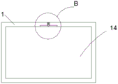
fig. 6 is an enlarged schematic structural diagram of the present invention at B in fig. 5.
The reference numbers in the figures illustrate:
1 ash shovel hopper, 2 ash collecting hoppers, 3 shovel boards, 4 filter screens, 5 ash scraping boards, 6 second rotating shafts, 7 belts, 8 driving shafts, 9 driving belts, 10 cams, 11 first rotating shafts, 12 torsion springs, 13 ash blocking boards, 14 ash discharging doors, 15 retaining rings and 16 buckles.
Detailed Description
The technical solution in the embodiment of the present invention will be clearly and completely described below with reference to the accompanying drawings in the embodiment of the present invention; obviously, the described embodiments are only a part of the embodiments of the present invention, and not all embodiments, and all other embodiments obtained by those skilled in the art without any inventive work are within the scope of the present invention based on the embodiments of the present invention.
In the description of the present invention, it should be noted that the terms "upper", "lower", "inner", "outer", "top/bottom", and the like indicate orientations or positional relationships based on the orientations or positional relationships shown in the drawings, and are only for convenience of description and simplification of description, but do not indicate or imply that the device or element referred to must have a specific orientation, be constructed in a specific orientation, and be operated, and thus, should not be construed as limiting the present invention. Furthermore, the terms "first" and "second" are used for descriptive purposes only and are not to be construed as indicating or implying relative importance.
In the description of the present invention, it is to be noted that, unless otherwise explicitly specified or limited, the terms "mounted", "provided", "sleeved/connected", "connected", and the like are to be understood in a broad sense, such as "connected", which may be fixedly connected, detachably connected, or integrally connected; can be mechanically or electrically connected; they may be connected directly or indirectly through intervening media, or they may be interconnected between two elements. The specific meaning of the above terms in the present invention can be understood in specific cases to those skilled in the art.
Example 1:
referring to fig. 1-6, an ash collecting device for a concrete pavement ash removing machine comprises an ash bucket 1 and an ash bucket 2, referring to fig. 2, an obliquely arranged shovel plate 3 is arranged in the ash bucket 1, a filter screen 4 is arranged in the middle of the shovel plate 3, a first rotating shaft 11 is inserted in the shovel plate 3, two ends of the first rotating shaft 11 are rotatably connected with the side wall of the ash bucket 1, two ends of the first rotating shaft 11, which are close to the side wall of the ash bucket 1, are sleeved with torsion springs 12, referring to fig. 3, a conveying device which is obliquely arranged is arranged below the shovel plate 3, the conveying device comprises a driving shaft 8 and a plurality of driven shafts, the driving shaft 8 and the driven shafts are rotatably connected to the side wall of the ash bucket 1, one end of the driving shaft 8 penetrates through the side wall of the ash bucket 1 and is fixedly connected with a second belt pulley, the second belt pulley is connected with the first belt pulley through a belt 7, the driving shaft 8 is in transmission connection with the driven, the transmission belt 9 is provided with a plurality of ash baffles 13 which are obliquely arranged, the transmission device with the ash baffles 13 can separate fine ash and large residue blocks after screening, and then transmit the fine ash to the ash collecting hopper 2 through the transmission belt, so that dust can be conveniently collected, a second rotating shaft 6 is inserted on the side wall of the ash removing hopper 1 above the shovel plate 3, one end of the second rotating shaft 6 penetrates through the side wall of the ash removing hopper 1 and is welded with a first belt pulley, the other end of the second rotating shaft 6 penetrates through the side wall of the ash removing hopper 1 and is fixedly connected with an output shaft of a motor, the motor is Y100L-2 in model, referring to figure 1, the ash removing plate 5 is welded on the second rotating shaft 6, the ash removing plate 5 is arranged in an arc shape, a rubber buffer protective sleeve is arranged at the edge of the ash removing plate 5 close to the filter screen 4, the arc-shaped ash removing plate 5 can improve the transmission effect of large residues, and the arranged rubber buffer protective sleeve can protect the filter screen 4 when, the service life of the filter screen 4 is prolonged, the cam 10 is fixedly sleeved on the second rotating shaft 6 close to the first belt pulley, the shovel plate 3 close to the cam 10 is provided with an arc-shaped groove, the arc-shaped groove can provide certain buffering when the cam 10 contacts with the shovel plate 3, the service life of parts is prolonged, referring to a graph 4, the rear side wall of the ash bucket 1 is provided with an ash unloading door 14, referring to the graph 6, the ash unloading door 14 is connected with the rear side wall of the ash bucket 1 through a hinge, a snap ring 15 is arranged above the ash unloading door 14, the rear side wall of the ash bucket 1 is provided with a snap ring 16 matched with the snap ring 16, through the matching of the snap ring 16 and the snap ring 15, a worker can conveniently clean residues in the ash bucket 2, through the arrangement of the filter screen 4, the cam 10 and other parts, the shovel plate 3 can slightly vibrate in the process of collecting the residues, the fine ash and the large residue blocks are separately conveyed to the ash collecting hopper 2, so that the dust is convenient to collect.
The working principle is as follows: when the ash removing machine starts to work, a worker turns on the motor, the motor can drive the shovel plate 6 to rotate, the cam 10 on the shovel plate 6 can be driven to rotate by the rotation of the shovel plate 6, the shovel plate 3 can be downwards extruded by the cam 10 through the arc-shaped groove, the shovel plate 3 can downwards rotate through the shovel plate 11, when the cam 10 rotates out of the arc-shaped groove, the shovel plate 3 can upwards move and recover under the action of the torsion spring 12, and the filter screen 4 in the shovel plate 3 has a vibration effect due to continuous up-and-down movement;
further, when the residues reach the shovel plate 3, the fine residues can enter the conveying device through the filter screen 4 and then are conveyed into the ash collecting hopper 2 through the conveying belt with the ash blocking plate 13, so that the fine residues are prevented from leaking;
further, large residue particles continue to move upwards into the dust hopper 2, and some blocked residue particles are also conveyed into the dust hopper 2 by the action of the dust scraper 5, so that the residue is prevented from sliding out of the shovel plate 3 by separated conveying and collecting, and the cleaning effect is enhanced.
Claims (5)
1. The utility model provides a collection grey device for concrete road surface deashing machine, includes shovel ash bucket (1) and collection ash bucket (2), its characterized in that: the ash shovel is characterized in that a shovel plate (3) placed in an inclined mode is arranged in the ash shovel hopper (1), a filter screen (4) is arranged in the middle of the shovel plate (3), a first rotating shaft (11) is inserted into the shovel plate (3), two ends of the first rotating shaft (11) are rotatably connected with the side wall of the ash shovel hopper (1), a torsion spring (12) is sleeved at two ends of the first rotating shaft (11) close to the side wall of the ash shovel hopper (1), a conveying device arranged in an inclined mode is installed below the shovel plate (3), a second rotating shaft (6) is inserted on the side wall of the ash shovel hopper (1) above the shovel plate (3), one end of the second rotating shaft (6) penetrates through the side wall of the ash shovel hopper (1) and is welded with a first belt pulley, the other end of the second rotating shaft (6) penetrates through the side wall of the ash shovel hopper (1) and is fixedly connected with an output shaft of a motor, and the ash shovel plate (5) is welded on the second rotating shaft (, close to first belt pulley fixed cover is equipped with cam (10) on second pivot (6), ash removal door (14) have been seted up to the rear end lateral wall of shovel ash bucket (1), connect through belt (7) transmission between first belt pulley and the conveyer.
2. The ash collecting device for the ash cleaning machine of the concrete pavement according to claim 1, which is characterized in that: an arc-shaped groove is formed in the shovel plate (3) close to the cam (10).
3. The ash collecting device for the ash cleaning machine of the concrete pavement according to claim 1, which is characterized in that: conveyer includes driving shaft (8) and a plurality of driven shaft, and driving shaft (8) and driven shaft rotate to be connected on the lateral wall of shovel ash bucket (1), the one end of driving shaft (8) runs through the lateral wall of shovel ash bucket (1) and fixed link has the second belt pulley, be connected through belt (7) between second belt pulley and the first belt pulley, be connected through drive belt (9) transmission between driving shaft (8) and the driven shaft, set up fender grey board (13) that a plurality of slopes set up on drive belt (9).
4. The ash collecting device for the ash cleaning machine of the concrete pavement according to claim 1, which is characterized in that: the ash discharging door (14) is connected with the rear side wall of the ash bucket (1) through a hinge, a retaining ring (15) is arranged above the ash discharging door (14), and a buckle (16) matched with the retaining ring (15) is installed on the rear side wall of the ash bucket.
5. The ash collecting device for the ash cleaning machine of the concrete pavement according to claim 1, which is characterized in that: scrape hawk (5) and be the arc setting, and scrape hawk (5) and be close to the border of filter screen and be provided with rubber buffering protective sheath.
Priority Applications (1)
| Application Number | Priority Date | Filing Date | Title |
|---|---|---|---|
| CN201921662441.2U CN211898066U (en) | 2019-10-02 | 2019-10-02 | Ash collecting device for concrete pavement ash cleaning machine |
Applications Claiming Priority (1)
| Application Number | Priority Date | Filing Date | Title |
|---|---|---|---|
| CN201921662441.2U CN211898066U (en) | 2019-10-02 | 2019-10-02 | Ash collecting device for concrete pavement ash cleaning machine |
Publications (1)
| Publication Number | Publication Date |
|---|---|
| CN211898066U true CN211898066U (en) | 2020-11-10 |
Family
ID=73286281
Family Applications (1)
| Application Number | Title | Priority Date | Filing Date |
|---|---|---|---|
| CN201921662441.2U Expired - Fee Related CN211898066U (en) | 2019-10-02 | 2019-10-02 | Ash collecting device for concrete pavement ash cleaning machine |
Country Status (1)
| Country | Link |
|---|---|
| CN (1) | CN211898066U (en) |
-
2019
- 2019-10-02 CN CN201921662441.2U patent/CN211898066U/en not_active Expired - Fee Related
Similar Documents
| Publication | Publication Date | Title |
|---|---|---|
| CN213493994U (en) | Concrete crushing and recycling device | |
| CN210103007U (en) | Grit conveyor | |
| CN114377822B (en) | Construction waste treatment equipment for civil engineering | |
| CN217250641U (en) | Solid waste sorting machine | |
| CN211898066U (en) | Ash collecting device for concrete pavement ash cleaning machine | |
| CN215611872U (en) | Abandonment changes breaker of tile manufacturing middlings | |
| CN211812031U (en) | Conveying mechanism for calcium carbonate processing | |
| CN210585376U (en) | Get rid of device of ferromagnetic impurity in concrete | |
| CN213833447U (en) | Dry-mixed mortar excess material recovery device | |
| CN214086413U (en) | Modified asphalt waterproofing membrane rock slice feeding system | |
| CN212424393U (en) | Grit conveyer | |
| CN210965854U (en) | Screening structure of intelligent mobile electric screen | |
| CN209318120U (en) | A kind of corncob dedusting removal of impurities cleaner | |
| CN114042635A (en) | Abrasive screening plant | |
| JPH09169424A (en) | Fallen material recovering device without using power source | |
| CN221208952U (en) | Sand screening device for building industry | |
| CN221643943U (en) | Slag micropowder conveying equipment with hierarchical screening function | |
| CN118205868B (en) | Plate feeder and feeding method | |
| CN215443803U (en) | Fireproof door leaf filler device | |
| CN218808617U (en) | Plate feeder with fine ore recovery function | |
| CN213103222U (en) | Oscillating screen | |
| CN117123305B (en) | Granule screening device and screening method | |
| CN118454789A (en) | Construction waste recycled aggregate crushing equipment | |
| CN220329267U (en) | Sand screening machine for building processing | |
| CN217369249U (en) | Full-automatic sieve surface fabric cleaning device |
Legal Events
| Date | Code | Title | Description |
|---|---|---|---|
| GR01 | Patent grant | ||
| GR01 | Patent grant | ||
| CF01 | Termination of patent right due to non-payment of annual fee |
Granted publication date: 20201110 Termination date: 20211002 |
|
| CF01 | Termination of patent right due to non-payment of annual fee |