CN211893393U - Ball and socket assembly - Google Patents
Ball and socket assembly Download PDFInfo
- Publication number
- CN211893393U CN211893393U CN201921105844.7U CN201921105844U CN211893393U CN 211893393 U CN211893393 U CN 211893393U CN 201921105844 U CN201921105844 U CN 201921105844U CN 211893393 U CN211893393 U CN 211893393U
- Authority
- CN
- China
- Prior art keywords
- ball
- bore
- socket assembly
- housing
- assembly
- Prior art date
- Legal status (The legal status is an assumption and is not a legal conclusion. Google has not performed a legal analysis and makes no representation as to the accuracy of the status listed.)
- Active
Links
Images


Classifications
-
- F—MECHANICAL ENGINEERING; LIGHTING; HEATING; WEAPONS; BLASTING
- F16—ENGINEERING ELEMENTS AND UNITS; GENERAL MEASURES FOR PRODUCING AND MAINTAINING EFFECTIVE FUNCTIONING OF MACHINES OR INSTALLATIONS; THERMAL INSULATION IN GENERAL
- F16C—SHAFTS; FLEXIBLE SHAFTS; ELEMENTS OR CRANKSHAFT MECHANISMS; ROTARY BODIES OTHER THAN GEARING ELEMENTS; BEARINGS
- F16C11/00—Pivots; Pivotal connections
- F16C11/04—Pivotal connections
- F16C11/06—Ball-joints; Other joints having more than one degree of angular freedom, i.e. universal joints
- F16C11/0685—Manufacture of ball-joints and parts thereof, e.g. assembly of ball-joints
-
- B—PERFORMING OPERATIONS; TRANSPORTING
- B23—MACHINE TOOLS; METAL-WORKING NOT OTHERWISE PROVIDED FOR
- B23P—METAL-WORKING NOT OTHERWISE PROVIDED FOR; COMBINED OPERATIONS; UNIVERSAL MACHINE TOOLS
- B23P11/00—Connecting or disconnecting metal parts or objects by metal-working techniques not otherwise provided for
- B23P11/005—Connecting or disconnecting metal parts or objects by metal-working techniques not otherwise provided for by expanding or crimping
-
- F—MECHANICAL ENGINEERING; LIGHTING; HEATING; WEAPONS; BLASTING
- F16—ENGINEERING ELEMENTS AND UNITS; GENERAL MEASURES FOR PRODUCING AND MAINTAINING EFFECTIVE FUNCTIONING OF MACHINES OR INSTALLATIONS; THERMAL INSULATION IN GENERAL
- F16C—SHAFTS; FLEXIBLE SHAFTS; ELEMENTS OR CRANKSHAFT MECHANISMS; ROTARY BODIES OTHER THAN GEARING ELEMENTS; BEARINGS
- F16C11/00—Pivots; Pivotal connections
- F16C11/04—Pivotal connections
- F16C11/06—Ball-joints; Other joints having more than one degree of angular freedom, i.e. universal joints
- F16C11/0619—Ball-joints; Other joints having more than one degree of angular freedom, i.e. universal joints the female part comprising a blind socket receiving the male part
- F16C11/0623—Construction or details of the socket member
- F16C11/0642—Special features of the plug or cover on the blind end of the socket
-
- F—MECHANICAL ENGINEERING; LIGHTING; HEATING; WEAPONS; BLASTING
- F16—ENGINEERING ELEMENTS AND UNITS; GENERAL MEASURES FOR PRODUCING AND MAINTAINING EFFECTIVE FUNCTIONING OF MACHINES OR INSTALLATIONS; THERMAL INSULATION IN GENERAL
- F16C—SHAFTS; FLEXIBLE SHAFTS; ELEMENTS OR CRANKSHAFT MECHANISMS; ROTARY BODIES OTHER THAN GEARING ELEMENTS; BEARINGS
- F16C11/00—Pivots; Pivotal connections
- F16C11/04—Pivotal connections
- F16C11/06—Ball-joints; Other joints having more than one degree of angular freedom, i.e. universal joints
- F16C11/068—Special features relating to lubrication
-
- F—MECHANICAL ENGINEERING; LIGHTING; HEATING; WEAPONS; BLASTING
- F16—ENGINEERING ELEMENTS AND UNITS; GENERAL MEASURES FOR PRODUCING AND MAINTAINING EFFECTIVE FUNCTIONING OF MACHINES OR INSTALLATIONS; THERMAL INSULATION IN GENERAL
- F16C—SHAFTS; FLEXIBLE SHAFTS; ELEMENTS OR CRANKSHAFT MECHANISMS; ROTARY BODIES OTHER THAN GEARING ELEMENTS; BEARINGS
- F16C11/00—Pivots; Pivotal connections
- F16C11/04—Pivotal connections
- F16C11/06—Ball-joints; Other joints having more than one degree of angular freedom, i.e. universal joints
- F16C11/0685—Manufacture of ball-joints and parts thereof, e.g. assembly of ball-joints
- F16C11/069—Manufacture of ball-joints and parts thereof, e.g. assembly of ball-joints with at least one separate part to retain the ball member in the socket; Quick-release systems
-
- B—PERFORMING OPERATIONS; TRANSPORTING
- B60—VEHICLES IN GENERAL
- B60G—VEHICLE SUSPENSION ARRANGEMENTS
- B60G2204/00—Indexing codes related to suspensions per se or to auxiliary parts
- B60G2204/40—Auxiliary suspension parts; Adjustment of suspensions
- B60G2204/416—Ball or spherical joints
-
- B—PERFORMING OPERATIONS; TRANSPORTING
- B60—VEHICLES IN GENERAL
- B60G—VEHICLE SUSPENSION ARRANGEMENTS
- B60G7/00—Pivoted suspension arms; Accessories thereof
- B60G7/005—Ball joints
-
- F—MECHANICAL ENGINEERING; LIGHTING; HEATING; WEAPONS; BLASTING
- F16—ENGINEERING ELEMENTS AND UNITS; GENERAL MEASURES FOR PRODUCING AND MAINTAINING EFFECTIVE FUNCTIONING OF MACHINES OR INSTALLATIONS; THERMAL INSULATION IN GENERAL
- F16C—SHAFTS; FLEXIBLE SHAFTS; ELEMENTS OR CRANKSHAFT MECHANISMS; ROTARY BODIES OTHER THAN GEARING ELEMENTS; BEARINGS
- F16C11/00—Pivots; Pivotal connections
- F16C11/04—Pivotal connections
- F16C11/06—Ball-joints; Other joints having more than one degree of angular freedom, i.e. universal joints
- F16C11/0619—Ball-joints; Other joints having more than one degree of angular freedom, i.e. universal joints the female part comprising a blind socket receiving the male part
- F16C11/0623—Construction or details of the socket member
- F16C11/0647—Special features relating to adjustment for wear or play; Wear indicators
-
- F—MECHANICAL ENGINEERING; LIGHTING; HEATING; WEAPONS; BLASTING
- F16—ENGINEERING ELEMENTS AND UNITS; GENERAL MEASURES FOR PRODUCING AND MAINTAINING EFFECTIVE FUNCTIONING OF MACHINES OR INSTALLATIONS; THERMAL INSULATION IN GENERAL
- F16C—SHAFTS; FLEXIBLE SHAFTS; ELEMENTS OR CRANKSHAFT MECHANISMS; ROTARY BODIES OTHER THAN GEARING ELEMENTS; BEARINGS
- F16C11/00—Pivots; Pivotal connections
- F16C11/04—Pivotal connections
- F16C11/06—Ball-joints; Other joints having more than one degree of angular freedom, i.e. universal joints
- F16C11/08—Ball-joints; Other joints having more than one degree of angular freedom, i.e. universal joints with resilient bearings
-
- F—MECHANICAL ENGINEERING; LIGHTING; HEATING; WEAPONS; BLASTING
- F16—ENGINEERING ELEMENTS AND UNITS; GENERAL MEASURES FOR PRODUCING AND MAINTAINING EFFECTIVE FUNCTIONING OF MACHINES OR INSTALLATIONS; THERMAL INSULATION IN GENERAL
- F16C—SHAFTS; FLEXIBLE SHAFTS; ELEMENTS OR CRANKSHAFT MECHANISMS; ROTARY BODIES OTHER THAN GEARING ELEMENTS; BEARINGS
- F16C2202/00—Solid materials defined by their properties
- F16C2202/02—Mechanical properties
- F16C2202/04—Hardness
-
- F—MECHANICAL ENGINEERING; LIGHTING; HEATING; WEAPONS; BLASTING
- F16—ENGINEERING ELEMENTS AND UNITS; GENERAL MEASURES FOR PRODUCING AND MAINTAINING EFFECTIVE FUNCTIONING OF MACHINES OR INSTALLATIONS; THERMAL INSULATION IN GENERAL
- F16C—SHAFTS; FLEXIBLE SHAFTS; ELEMENTS OR CRANKSHAFT MECHANISMS; ROTARY BODIES OTHER THAN GEARING ELEMENTS; BEARINGS
- F16C2226/00—Joining parts; Fastening; Assembling or mounting parts
- F16C2226/10—Force connections, e.g. clamping
- F16C2226/12—Force connections, e.g. clamping by press-fit, e.g. plug-in
-
- F—MECHANICAL ENGINEERING; LIGHTING; HEATING; WEAPONS; BLASTING
- F16—ENGINEERING ELEMENTS AND UNITS; GENERAL MEASURES FOR PRODUCING AND MAINTAINING EFFECTIVE FUNCTIONING OF MACHINES OR INSTALLATIONS; THERMAL INSULATION IN GENERAL
- F16C—SHAFTS; FLEXIBLE SHAFTS; ELEMENTS OR CRANKSHAFT MECHANISMS; ROTARY BODIES OTHER THAN GEARING ELEMENTS; BEARINGS
- F16C2326/00—Articles relating to transporting
- F16C2326/01—Parts of vehicles in general
- F16C2326/05—Vehicle suspensions, e.g. bearings, pivots or connecting rods used therein
-
- F—MECHANICAL ENGINEERING; LIGHTING; HEATING; WEAPONS; BLASTING
- F16—ENGINEERING ELEMENTS AND UNITS; GENERAL MEASURES FOR PRODUCING AND MAINTAINING EFFECTIVE FUNCTIONING OF MACHINES OR INSTALLATIONS; THERMAL INSULATION IN GENERAL
- F16C—SHAFTS; FLEXIBLE SHAFTS; ELEMENTS OR CRANKSHAFT MECHANISMS; ROTARY BODIES OTHER THAN GEARING ELEMENTS; BEARINGS
- F16C2326/00—Articles relating to transporting
- F16C2326/20—Land vehicles
- F16C2326/24—Steering systems, e.g. steering rods or columns
Abstract
The utility model provides a ball nest subassembly. The ball and socket assembly includes a housing having an inner surface surrounding an inner bore. The bore extends from an open first end to an open second end. The groove extends into the inner surface adjacent the second end. A ball stud having a ball head portion is disposed in the bore, wherein a shank portion of the ball stud extends through the open first end. The cover plate assembly is fixed to the housing. The outer member of the cap assembly has an outer periphery and a through bore. The outer periphery is secured in the groove. The inner part of the cover plate assembly is fixed in the through hole. The inner member includes an opening configured to receive a lube nozzle.
Description
Cross Reference to Related Applications
This application claims the benefit of U.S. provisional application serial No. 62/697,467, filed on 2018, 7, 13, which is incorporated herein by reference in its entirety.
Background of the utility model
1. Field of the invention
The present invention relates generally to a ball and socket assembly, such as of the type used in vehicle suspension and steering assemblies.
2. Background of the invention
Ball and socket assemblies (also known as ball joints) are commonly used in vehicle suspension and steering assemblies to allow two components (e.g., a control arm and a knuckle) to articulate, pivot, and/or rotate relative to each other during vehicle operation. Such socket assemblies typically include a housing fixedly attached to one of the components and a ball stud fixedly attached to the other component. Ball studs typically have a ball portion received in a bore of a housing, and a shank portion extending from the housing.
Typically, a closure feature is employed to capture the ball portion of the ball stud, one or more bearings, and a pretension in the internal bore of the housing. In some ball and socket assemblies, the closure feature is provided by a deformed end of the housing (e.g., by swaging or by crimping the end of the housing). In other ball joints, the component is inserted into the bore through an open end of the housing, and the closure feature is provided via a cover plate for closing the open end. It is known that such a cover plate is fixedly attached to the housing by: the cover plate is screwed onto the housing or pressed (i.e., flattened) from a frustoconical shape into a flat shape, causing the cover plate to radially expand such that the outer periphery of the cover plate is fixedly seated within a preformed groove in the inner bore of the housing.
While the above ball joint assemblies may prove effective in use, problems are encountered, particularly due to their structure and method of construction. For example, with press-in cover plates, problems may arise due to the formation of openings for receiving a grease nipple (typically incorporated for injecting lubricant into the internal bore of the housing). In some cases, a pin (plug) is inserted into a preformed opening in the cover plate and retained in the preformed opening during the pressing operation to maintain the size of the preformed opening as the cover plate is pressed and flattened. Then, a self-tapping lubricating nozzle is screwed into the preformed opening. However, the self-tapping lubricating nozzle having a self-tapping thread is expensive relative to a conventional lubricating nozzle having no self-tapping thread, and further, the self-tapping lubricating nozzle is generally more difficult and complicated to install, thereby increasing the cost of manufacture. Thus, in another example, to avoid the above-described problems associated with preformed openings and self-tapping lubricating nipples, it is known to tap the opening after the cover plate is flattened. However, this process not only requires an additional expensive tapping step in manufacture, but also results in the formation of loose metal shavings, risking leaving at least some of the metal shavings in the internal bore.
SUMMERY OF THE UTILITY MODEL
This section provides a general overview of some of the objects, advantages, aspects, and features provided by the inventive concepts associated with the present disclosure. This section, however, is not intended to be an exhaustive or comprehensive list of all of the objects, advantages, aspects and features of the present disclosure.
It is an object of the present disclosure to provide a ball and socket assembly that overcomes the disadvantages of known ball and socket assemblies.
It is a further object of the present disclosure to provide a ball and socket assembly that is economical to manufacture and assemble and exhibits a long service life.
In accordance with these objects, and others that will be appreciated by those skilled in the art of ball and socket assemblies, the present disclosure is directed to providing a ball and socket assembly for an automotive vehicle.
According to one aspect, the present disclosure relates to a ball and socket assembly that advances the art and improves currently known ball and socket assemblies for motor vehicles.
In accordance with these and other objects, advantages and aspects, a ball and socket assembly is provided that includes a housing having an inner surface surrounding a bore extending from an open first end to an open second end, and a groove extending into the inner surface adjacent the second end. At least one bearing surface is provided in the bore. A ball stud having a ball head portion is disposed in the bore in engagement with the at least one bearing surface, and a shank portion of the ball stud extends through the open first end. The socket assembly further includes a cover plate assembly having an outer member and an inner member. The outer member is provided with an outer periphery and a through hole, the outer periphery being fixed in the groove, and the inner member being fixed in the through hole of the outer member. The inner member includes an opening (e.g., a central opening) configured to receive a lube nozzle.
According to another aspect, the inner part is made of a first material and the outer part is made of a second material, wherein the first material is harder than the second material. The relative increase in hardness of the inner member facilitates assembly while preventing the inner member from being damaged or otherwise deformed during assembly, thus facilitating the formation of a lubricated tight seal between the nipple and the inner member.
According to another aspect, the central opening in the inner member may be threaded to facilitate threading the lube nozzle into the central opening.
According to another aspect, the inner member may be provided with a cylindrical portion fixed in the through hole of the outer member, and a flange portion configured to cover an upper surface of the outer member.
According to another aspect, at least one gripping feature may be provided extending radially outward from the cylindrical portion of the inner member, wherein the gripping feature is embedded in the outer member to assist in maintaining the inner member in a fixed, sealing relationship with the outer member.
According to another aspect, the at least one gripping feature may include a pair of gripping features axially spaced from one another.
According to another aspect, the at least one gripping feature may be provided as an annular protrusion, establishing a full circumferential sealing and locking engagement with the outer member.
According to another aspect, the ball and socket assembly may further include at least one bearing disposed in the bore, and a pretensioning member sandwiched between the outer member and the at least one bearing in axially compressed, pretensioned relationship between the bearing and the outer member.
According to another aspect, the outer periphery of the outer member may be secured within the groove of the housing with an interference fit and the inner member may be secured within the through bore of the outer member with an interference fit, wherein the interference fit eliminates the need to introduce a secondary securing and/or secondary sealing mechanism.
Drawings
These and other objects, features and advantages of the present invention will become more readily understood when considered in connection with the following description of the presently preferred embodiments, the appended claims, and the accompanying drawings, in which:
FIG. 1 is a perspective view of a motor vehicle including one or more ball and socket assemblies constructed in accordance with the present disclosure;
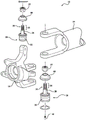
FIG. 1A illustrates an exploded partial view of components of a vehicle suspension in which a ball and socket assembly constructed in accordance with the present disclosure may be used, the illustratively shown steering knuckle including a pair of ball and socket assemblies constructed in accordance with an aspect of the present disclosure;
FIG. 2 is a cross-sectional view of an exemplary embodiment of an assembled ball and socket assembly constructed in accordance with an aspect of the present disclosure;
FIG. 3 is an exploded cross-sectional view of the cover-plate assembly of the ball-and-socket assembly of FIG. 2, showing the inner member of the cover-plate assembly prior to assembly to the outer member of the cover-plate assembly;
FIG. 3A is a cross-sectional view of an inner component of the cover plate assembly of FIGS. 2 and 3;
FIG. 3B is a view similar to FIG. 3 showing the inner member of the cover-plate assembly assembled to the outer member of the cover-plate assembly, the cover-plate assembly shown in a pre-assembled state prior to assembly to the housing of the ball-and-socket assembly of FIG. 2;
FIG. 4 is a view similar to FIG. 2 showing the cover-plate assembly disposed within the bore of the housing, wherein the cover-plate assembly is shown prior to a pressing operation for assembling the cover-plate assembly to the housing of the ball-and-socket assembly;
FIG. 4A is a view similar to FIG. 4, showing a force being applied to the cover plate assembly to assemble the cover plate assembly to the housing, the cover plate assembly being shown in an intermediate assembled state of the housing;
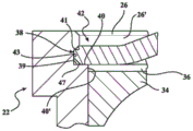
FIG. 5A is an enlarged cross-sectional view of the encircled area 5A of FIG. 2;
FIG. 5B is an enlarged cross-sectional view of the encircled area 5B of FIG. 2; and is
FIG. 6 is a flow chart illustrating a method of constructing a ball and socket assembly according to another aspect of the present disclosure.
Detailed Description
Referring to the drawings, wherein like reference numbers represent corresponding parts throughout the several views, unless otherwise noted, there is shown in fig. 1a motor vehicle 10 wherein the motor vehicle 10 has at least one ball joint, also referred to as a socket assembly or ball-and-socket assembly 20 constructed in accordance with an aspect of the present disclosure, incorporated into a vehicle suspension and/or steering component thereof, such as in one or more components of an axle assembly 12, such as the assembly 12 including an axle 14 and/or a steering knuckle 16 supporting a hub (not shown) for rotation therewith. It should be appreciated that the axle assembly 12 and steering knuckle 16 illustrated in FIG. 1A need not be from a conventional vehicle, and the illustration is provided merely to illustrate the potential use of the ball and socket assembly 20, such as in various components of a vehicle suspension and/or steering assembly. A pair of ball and socket assemblies 20 operatively attach (also referred to as couple) the steering knuckle 16 with the axle 14 (such as the illustrated or differently configured axle) for pivotal movement relative thereto by way of example and not limitation. As will be explained in further detail below, ball and socket assembly 20 and method of construction thereof overcome the disadvantages of known ball and socket assemblies and methods of construction thereof, such as those discussed above, as will be readily appreciated by those of ordinary skill in the ball and socket assembly art.
Referring now to fig. 2, ball and socket assembly 20 includes a housing 22 having an inner surface 21 surrounding an inner bore 23 extending along a central axis a from an open first end 24 to an open second end 26. In the exemplary embodiment, by way of example and not limitation, housing 22 has a box-like structure with an outer surface 25, such as a cylindrical outer surface, that is designed to be press-fit into a similarly shaped opening of another component, such as a control arm (not shown). However, it should be understood that the housing 22 may alternatively be integrally formed with the other components. The housing 22 is preferably made as a single piece of metal (e.g., steel or alloy steel) and may be formed by any suitable process or combination of processes including casting, forging, and machining.
The ball and socket assembly 20 also includes a ball stud 28 having a spherical head portion 30 and a shank portion 32. The ball studs 28 are shown aligned with one another along a common vertical axis to allow the steering knuckle 16 to pivot about the vertical axis relative to the axle 14 in response to steering inputs from the vehicle operator. The ball portion 30 is inserted into the internal bore 23 of the housing 22, and the shank portion 32 extends from the ball portion 30 out of the housing 22 through the open first end 24 to the attachment end 33. To facilitate attachment of the attachment end 33 to a vehicle component (e.g., a control arm), the attachment end 33 is shown with an externally threaded region 35 configured for a threaded attachment nut 37. The ball stud 28 is preferably made as a single piece of metal (e.g., steel or alloy steel) and may be formed by any suitable process or combination of processes including casting, forging, and machining.
A bearing 34 is shown disposed in the housing 22 adjacent the open second end 26 and has a curved bearing surface, such as a concave hemispherical surface, that is in mating contact with the ball portion 30 of the ball stud 28 to allow the ball stud 28 and the housing 22 to articulate and rotate relative to each other as needed. The bearing 34 is preferably made of a suitable bearing grade plastic or metal, and may be formed by any suitable process or combination of processes. Those of ordinary skill in the art will appreciate that other bearing arrangements are possible, including having a plurality of bearings axially spaced from one another for engaging opposite hemispheres of the ball portion 30, by way of example and not limitation. A pretensioning member 36, such as a spring member (e.g., a washer spring, sometimes also referred to as a Belleville washer), may also be disposed in the inner bore 23 to minimize or eliminate axial play, sometimes referred to as dirty oil, between the ball head portion 30 and the bearing 34. In the non-limiting embodiment shown, a pretensioning member 36 is shown in direct contact with bearing 34 on the opposite side of bearing 34 relative to ball stud 28 for pretensioning a curved bearing surface against ball portion 30 of ball stud 28. It should be understood that the pretensioning member 36 can be spaced from and remain in operative communication with the bearing 34, if desired, to maintain the desired pretension (via one or more intermediate washers, etc.). Pretensioning member 36 also allows bearing 34 and ball stud 28 to deflect in an axial direction or move simultaneously with each other, thereby acting to dampen impact loads throughout ball-and-socket assembly 20. While only one pretensioning member 36 is included in the non-limiting exemplary embodiment, it should be appreciated that the ball and socket assembly 20 may alternatively include two or more bearings.
Adjacent the open second end 26, the groove 38 extends radially outward into the inner surface 21 of the housing 22, wherein the groove 38 may be formed as an annular groove extending circumferentially three hundred sixty degrees (360 °) about the central axis a. The recess 38 has a lower surface 39, an upper surface 41, and a sidewall 43 extending between the upper surface 39 and the lower surface 41, wherein the upper surface 39 and the lower surface 41 are generally parallel to each other. A lower surface 39 extends radially inwardly from groove 38 to define an exposed shoulder 40 (exposed means that shoulder 40 is visible downwardly along axis a as viewed in fig. 2). Thus, as best shown in fig. 5A, the shoulder 40 extends radially inwardly further than and beyond the upper surface 41, wherein the upper surface 41 of the groove 38 is defined by a depending annular lip 26' that is partially defined by the second end 26 of the housing 22. Accordingly, annular lip 26 ' has an inner diameter ID-1, and shoulder 40 and inner edge 40 ' of shoulder 40 have an inner diameter ID-2, wherein inner diameter ID-2 is less than inner diameter ID-1 of lip 26 ' of open second end 26 of housing 22.
A cover plate assembly 42 is received and secured in the recess 38 to close the second end 26 of the housing 22. The cover plate assembly 42 prevents contaminants from entering the internal bore 23 and capturing the ball portion 30 of the ball stud 28, the bearing 34, and the pretensioning member 36 within the internal bore 23, wherein the required axial pretension is automatically applied between the ball stud 28, the bearing 34, and the pretensioning member 36 when the cover plate assembly 42 is secured within the groove 38. The cover-plate assembly 42 has a central opening 44, wherein the central opening 44 is configured to releasably receive a lube nipple 45 (also referred to as a fuel nipple) for delivering lubricant (e.g., grease) into the internal bore 23 during initial assembly and during routine maintenance of the ball-and-socket assembly 20. To facilitate releasably receiving the grease fitting 45, the central opening 44 may be formed as a female threaded central opening 44, wherein the grease fitting 45 may be provided with external male threads sized for threaded receipt in the threaded central opening 44. The increased stiffness of the inner member 48 relative to the outer member 46 prevents deformation of the central opening 44 if inserted after the cover plate assembly 42 is assembled to the housing 22, thereby ensuring easy insertion of the grease fitting 45 into the central opening 44 and no complications. Accordingly, the central opening 44, and any female threads therein (if provided), are assured to remain in a circular, cylindrical configuration for matingly receiving the grease fitting 45, and any male threads thereon (if provided).
Referring now to fig. 2 and 3, the cover plate assembly 42 includes two pieces that are formed separately from one another as distinct pieces of material. Specifically, the cap plate assembly 42 includes an outer component 46 (also referred to as an outer member), and an inner component 48 (also referred to as an inner member). The inner member 48 is preferably made of a first material and the outer member 46 is made of a second material, wherein the first material of the inner member 48 is harder than the second material of the outer member 46. As best shown in fig. 2 and 3, the outer member 46 is preformed to have a frustoconical shape (i.e., a shape similar to a cone having a base, also referred to as a bottom end 47, and a peak, also referred to as a top end 49, with a frustoconical shape formed at a throughbore 51 having an inner diameter ID at the top end 49). Before the outer piece 46 is flattened, the bottom end 47 has an outer periphery 58 with an outer diameter OD that is less than the innermost diameter ID-1 of the open second end 26 of the housing 22 and that is greater than the inner diameter ID-2 of the shoulder 40. Thus, it is ensured that the shoulder 40 supports the bottom end 47 thereon, thereby preventing the passage of the outer member 46. The through-hole 51 has an inner surface 53 (fig. 3) that tapers radially outward such that the inner surface 53 diverges at an angle a relative to the central axis a. The inner surface 53 is shown as extending generally transversely to the generally parallel, planar surfaces (also referred to as faces 55, 55') of the outer member 46.
As best shown in fig. 3A, the inner member 48 is preformed to have a cylindrical body (also referred to as a cylindrical portion 50), and a flange portion 52. The flange portion 52 extends radially outward from the upper end of the cylindrical portion 50. The threaded central opening 44 is formed to extend along at least a portion of the inner surface of the cylindrical portion 50 and is shown extending the entire axial length of the inner member 48. The outer surface of the cylindrical portion 50 is shown with a gripping feature, which in a non-limiting embodiment is shown as a pair of axially spaced barbs 54. Barbs 54 extend radially outward from the outer surface of cylindrical portion 50, wherein barbs 54 may be formed as annular ribs (also referred to as protrusions 54) having an OD-1 that extends circumferentially about central axis a around the entire cylindrical portion 50. As shown, it should be understood that the gripping features 54 may be a single gripping feature or more than one pair.
As shown in fig. 4 and graphically represented in fig. 6, a method 1000 of constructing and assembling the ball and socket assembly 20 is provided. The method of construction and assembly of ball and socket assembly 20 begins at step 100 by inserting the ball portion 30 of ball stud 28, bearing 34 and pretensioning member 36 into the inner bore 23 of housing 22. Ball stud 28 extends through open first end 24, and ball portion 30 engages bearing surface 56, shown in the non-limiting embodiment as forming an integral part of housing 22, however, bearing surface 56 may be provided as: a separate bearing abutting a support surface of the housing 22, e.g. fixed to the support surface of the housing 22 (which may be a shoulder forming an integral part with the housing 22); or a separate support surface secured to the housing 22, such as a snap ring (not shown) disposed in an annular groove (not shown) in the housing 22. Next, at step 150, the inner member 48 of the cap assembly 42 is inserted into the through bore 51 of the outer member 46. The tapered inner surface 53, and preferably the inner diameter ID of the throughbore 51, which is larger in diameter than the outer diameter OD-1 of the cylindrical portion 50 (including the outer diameter of the gripping feature 54), allows the cylindrical portion 50 of the inner member 48 to be more easily positioned and inserted into the opening of the outer member 46 with a slight clearance fit, with the flange portion 52 in overlapping engagement with the flat upper surface 55 of the outer member 46. It should be understood that a two-wire or slight interference fit between cylindrical portion 50 and tip 49 is contemplated herein. Then, at step 200, the cap plate assembly 42 is inserted into the internal bore 23 of the housing 22 such that the outer periphery 58 of the bottom end 47 passes over the annular lip 26' adjacent the second end 26 in a slight clearance relationship therewith until the bottom end 47 of the outer member 46 comes into resting engagement against the shoulder 40.
Then, at step 250, as depicted in fig. 4A, a downward force F is applied to the cap assembly 42, plastically deforming the outer piece 46. Because the inner member 48 is made of a harder material than the outer member 46, the downward force F may be concentrated on the upper surface of the flange portion 52 of the inner member 48 while the inner member 48 resists deformation, thereby causing the outer diameter OD of the outer periphery 58 of the outer member 46 to increase and expand radially outward into the groove 38 of the housing 22. As the conical shape of the outer member 46 is generally flattened and the outer member 46 plastically deformed, the outer diameter OD of the outer member 46 continues to expand until it forms a fixed relationship within the groove 38 such that an interference fit is formed between the outer periphery 58 of the outer member 46. The interference fit may be formed at least one of: between the outer perimeter 58 and the cylindrical sidewall 43 of the recess 38, and/or between the outer perimeter 58 and the upper and lower surfaces 39, 41 of the recess 38. Upon plastic deformation of the outer member 46, the outer diameter OD permanently increases to OD '(FIG. 2), which is greater than the inner diameter ID-1 of the annular lip 26' adjacent the second end 26 of the housing 22. In this manner, outer periphery 58 is permanently secured within groove 38 with an interference fit, and thus, cover plate assembly 42 is permanently secured to housing 22 due to plastic deformation of outer member 46.
The radial expansion of the outer member 46 causes the inner member 48 to be simultaneously secured within the throughbore 51 of the outer member 46. As the bottom end 47 expands radially, the inner diameter ID of the throughbore 51 of the outer member 46 contracts and plastically deforms to a reduced diameter ID '(fig. 5B), wherein ID' is less than the outer diameter OD-1 of the barbs 54 and the cylindrical portion 50, thereby creating an interference fit between the inner surface 53 of the outer member 46 and the gripping feature 54 of the inner member 48, wherein the gripping feature 54 is embedded in the inner surface 53 of the outer member 46. Establishing respective interference fits between the housing 22 and the outer piece 46, and between the outer piece 46 and the inner piece 48, not only permanently secures the outer piece 46 to the housing 22 and the inner piece 48 to the outer piece 46, but also establishes fluid tight seals between the housing 22 and the outer piece 46, and between the outer piece 46 and the inner piece 48. In this way, it is ensured that lubricant (e.g., grease) remains sealed within the internal bore 23. It should be appreciated that the barbs 54 on the inner member 48 improve the strength of the interference fit between the outer member 46 and the inner member 48. At the completion of the pressing process, the pretensioning member 36 (sandwiched between the outer part 46 and the bearing 34) automatically applies the required pretension between the ball portion 30 and the bearing 34.
Then, at step 300, the grease nipple 45 may be inserted into the central opening 44 in a reliable, simple manner and without complications, primarily as a result of the inner member 48 being constructed of a harder material relative to the outer member 46, which resists deformation, wherein the inner member 48 may be formed of hardened stainless steel or other hardened metal, if desired. To facilitate assembly of the grease fitting 45 into the central opening 44, the central opening 44 may be provided with internal female threads, and the grease fitting 45 may be provided with external male threads sized for mating in threaded engagement with one another. Accordingly, assembly may include threading grease fitting 45 into central opening 44 after cover plate assembly 42 is pressed into fixed attachment with housing 22. Of course, it is contemplated herein that the grease fitting 45 may be preassembled within the central opening 44 prior to the pressing operation if desired, wherein a compression sleeve having a clearance fit with respect to the grease fitting may be used to avoid damaging the grease fitting 45 when the cover plate assembly 42 and its outer member 46 are pressed into fixed attachment with the groove 38.
In some vehicles, the ball and socket assembly 20 must be installed in a very narrow location. The threads on cover-plate assembly 42 allow grease fitting 45 to be removed prior to installation to reduce the axial dimension of ball and socket assembly 20, and then reinstalled with minimal effort. Moreover, after flattening, cover-plate assembly 42 has a very small axial profile such that it does not substantially increase the axial length of ball-and-socket assembly 20.
Obviously, many modifications and variations of the present invention are possible in light of the above teachings. It should be understood that although the ball and socket assembly 20 is depicted in a suspension/steering application of the motor vehicle 10, other applications within the motor vehicle 10, as well as other non-vehicular applications, are also contemplated herein. Furthermore, it is also contemplated that the claims and all features of all embodiments may be combined with each other, as long as such combinations are not mutually inconsistent. It is, therefore, to be understood that within the scope of the appended claims, the invention may be practiced otherwise than as specifically described.
Claims (9)
1. A socket assembly, comprising:
a housing having an inner surface surrounding a bore extending from an open first end to an open second end, a groove extending into the inner surface adjacent the second end;
at least one bearing surface provided in the bore;
a ball stud having a ball portion disposed in said bore in engagement with said at least one bearing surface and having a shank portion extending through said open first end; and
a cover plate assembly having an outer member and an inner member, the outer member having an outer periphery and a through bore, the outer periphery being secured in the groove and the inner member being secured in the through bore, the inner member having a central opening configured to receive a lubricant nozzle.
2. The ball and socket assembly of claim 1, wherein the inner member is made of a first material and the outer member is made of a second material, wherein the first material is harder than the second material.
3. The ball and socket assembly of claim 1, wherein the central opening is threaded.
4. The ball and socket assembly of claim 1, wherein the inner member has a cylindrical portion fixed in the through bore and a flange portion covering an upper surface of the outer member.
5. The ball and socket assembly of claim 4, further comprising at least one gripping feature extending radially outward from the cylindrical portion, the gripping feature embedded in the outer member.
6. The ball and socket assembly of claim 5, wherein the at least one gripping feature comprises a pair of gripping features axially spaced from one another.
7. The ball and socket assembly of claim 5, wherein the at least one gripping feature is an annular protrusion.
8. The ball and socket assembly of claim 1, further comprising at least one bearing disposed in the bore, and a pretensioning member sandwiched between an outer member and the at least one bearing.
9. The ball and socket assembly of claim 1, wherein the outer periphery is secured within the recess with an interference fit and the inner member is secured within the through bore with an interference fit.
Applications Claiming Priority (2)
| Application Number | Priority Date | Filing Date | Title |
|---|---|---|---|
| US201862697467P | 2018-07-13 | 2018-07-13 | |
| US62/697,467 | 2018-07-13 |
Publications (1)
| Publication Number | Publication Date |
|---|---|
| CN211893393U true CN211893393U (en) | 2020-11-10 |
Family
ID=69140227
Family Applications (2)
| Application Number | Title | Priority Date | Filing Date |
|---|---|---|---|
| CN201980047087.9A Active CN112424490B (en) | 2018-07-13 | 2019-07-11 | Socket assembly with gland plate and method of construction thereof |
| CN201921105844.7U Active CN211893393U (en) | 2018-07-13 | 2019-07-15 | Ball and socket assembly |
Family Applications Before (1)
| Application Number | Title | Priority Date | Filing Date |
|---|---|---|---|
| CN201980047087.9A Active CN112424490B (en) | 2018-07-13 | 2019-07-11 | Socket assembly with gland plate and method of construction thereof |
Country Status (4)
| Country | Link |
|---|---|
| US (1) | US11441597B2 (en) |
| CN (2) | CN112424490B (en) |
| DE (1) | DE112019003571T5 (en) |
| WO (1) | WO2020014433A1 (en) |
Families Citing this family (4)
| Publication number | Priority date | Publication date | Assignee | Title |
|---|---|---|---|---|
| RU2730763C1 (en) * | 2017-08-16 | 2020-08-26 | Малтиматик Инк. | Ball hinge with insert produced by injection molding |
| US11504833B2 (en) * | 2021-03-16 | 2022-11-22 | Federal-Mogul Motorparts Llc | Method of manufacturing ball joint with a threaded domed cover plate |
| US11708852B2 (en) * | 2021-06-27 | 2023-07-25 | Federal-Mogul Motorspots Llc | Ball joint, method of manufacturing a ball joint, and tool for manufacturing a ball joint |
| US20230078767A1 (en) * | 2021-09-14 | 2023-03-16 | Tien-I Industrial Co., Ltd. | Universal joint |
Family Cites Families (20)
| Publication number | Priority date | Publication date | Assignee | Title |
|---|---|---|---|---|
| US3269758A (en) * | 1964-01-29 | 1966-08-30 | Lemfoerder Metallwaren Ag | Ball joint device |
| GB992100A (en) * | 1964-03-03 | 1965-05-12 | William Charles Wehner | Swivel joint |
| FR1407330A (en) * | 1964-03-03 | 1965-07-30 | Ball joint | |
| US4358211A (en) * | 1971-09-09 | 1982-11-09 | General Motors Corporation | Pivot joint with visual preload indicator |
| CA960053A (en) * | 1971-09-09 | 1974-12-31 | General Motors Corporation | Pivot joint with visual preload indicator |
| US3791748A (en) * | 1972-04-17 | 1974-02-12 | Dart Ind Inc | Ball joint with manually operable, sensible wear indicator |
| US3813178A (en) * | 1972-08-10 | 1974-05-28 | Trw Inc | Wear indicating joint |
| US3960457A (en) * | 1974-12-20 | 1976-06-01 | Gulf & Western Manufacturing Company (Michigan) | Wear indicator for ball joints |
| GB1547202A (en) | 1976-09-21 | 1979-06-06 | Automotive Prod Co Ltd | Ball and sockets joints having a wear indicator |
| US4576499A (en) * | 1981-04-06 | 1986-03-18 | O & S Manufacturing Company | Ball and socket joints with wear indicator |
| JPS60208622A (en) * | 1984-03-30 | 1985-10-21 | Musashi Seimitsu Kogyo Kk | Ball joint |
| JPS6127305A (en) * | 1984-07-19 | 1986-02-06 | Musashi Seimitsu Kogyo Kk | Wear indicating ball joint |
| ATE170812T1 (en) * | 1993-12-17 | 1998-09-15 | Chrysler Corp | BALL JOINT |
| US5655848A (en) * | 1995-05-15 | 1997-08-12 | Chrysler Corporation | Suspension ball joint |
| US5676485A (en) * | 1996-03-28 | 1997-10-14 | Central Corporation | Ball joint used for steering arrangement or joint of suspension system of automobile |
| US6152637A (en) | 1998-04-27 | 2000-11-28 | Dana Corporation | Independent wear indicator assembly for vehicular steering knuckles ball & socket joints and other similar devices |
| US6202280B1 (en) | 1998-10-07 | 2001-03-20 | Federal-Mogul Corporation | Cover-plate expansion assembly method |
| CN2700184Y (en) | 2004-03-15 | 2005-05-18 | 张声良 | Wearproof and non-falling off vehicular ball pin assembly capable of automatically adjusting pretightening force |
| CN1968768A (en) * | 2004-04-21 | 2007-05-23 | 费德罗-莫格尔公司 | Method and apparatus for clearance adjusting cover plate closure |
| US20060029461A1 (en) * | 2004-08-05 | 2006-02-09 | Trw Automotive U.S. Llc | Ball joint assembly with wear indicating electrical circuit |
-
2019
- 2019-07-10 US US16/507,686 patent/US11441597B2/en active Active
- 2019-07-11 DE DE112019003571.1T patent/DE112019003571T5/en active Pending
- 2019-07-11 CN CN201980047087.9A patent/CN112424490B/en active Active
- 2019-07-11 WO PCT/US2019/041330 patent/WO2020014433A1/en active Application Filing
- 2019-07-15 CN CN201921105844.7U patent/CN211893393U/en active Active
Also Published As
| Publication number | Publication date |
|---|---|
| US20200018347A1 (en) | 2020-01-16 |
| CN112424490B (en) | 2023-05-05 |
| DE112019003571T5 (en) | 2021-04-08 |
| US11441597B2 (en) | 2022-09-13 |
| WO2020014433A1 (en) | 2020-01-16 |
| CN112424490A (en) | 2021-02-26 |
Similar Documents
| Publication | Publication Date | Title |
|---|---|---|
| CN211893393U (en) | Ball and socket assembly | |
| EP1866552B1 (en) | Metal split bearing compression load ball joint | |
| CN109312775B (en) | Socket assembly and method of manufacturing socket assembly | |
| US20050220531A1 (en) | Metal split bearing compression load ball joint | |
| CN109312776B (en) | Socket assembly and method of manufacturing socket assembly | |
| CN107250578A (en) | Globe joint component | |
| US20070166096A1 (en) | Joint assembly | |
| US6619873B2 (en) | Device and method for closing movable socket assemblies by expanding solid cover plates | |
| EP1792091A2 (en) | Joint assembly | |
| US6371682B1 (en) | Anchor post non-articulating idler socket joint | |
| US11396906B2 (en) | Ball socket assembly with a preload bearing | |
| CN112654795B (en) | Ball joint assembly | |
| CN211778499U (en) | Ball and socket assembly and solid axle assembly in a vehicle | |
| CN112041572B (en) | Compression loaded ball and socket assembly | |
| US10584737B2 (en) | Compression loaded ball socket assembly | |
| EP2069648A2 (en) | Light weight ball joint |
Legal Events
| Date | Code | Title | Description |
|---|---|---|---|
| GR01 | Patent grant | ||
| GR01 | Patent grant |