CN211891029U - Automatic trimming and winding machine for rubber films - Google Patents
Automatic trimming and winding machine for rubber films Download PDFInfo
- Publication number
- CN211891029U CN211891029U CN202020285103.8U CN202020285103U CN211891029U CN 211891029 U CN211891029 U CN 211891029U CN 202020285103 U CN202020285103 U CN 202020285103U CN 211891029 U CN211891029 U CN 211891029U
- Authority
- CN
- China
- Prior art keywords
- frame
- knife
- trimming
- roller
- knife roll
- Prior art date
- Legal status (The legal status is an assumption and is not a legal conclusion. Google has not performed a legal analysis and makes no representation as to the accuracy of the status listed.)
- Active
Links
Images


Abstract
An automatic trimming and coiling machine for rubber films belongs to the field of rubber machinery and comprises a frame, a knife roll, a lead-in frame, a coiling frame and a motor, wherein the frame is of a frame structure; the knife roll consists of an upper knife roll and a lower knife roll and comprises an installation frame, a knife roll shaft, a trimming knife and a roller wheel, wherein the installation frame consists of two parts which are connected with the left side and the right side of the high end of the rack; the trimming knife is of a knife flywheel structure and consists of four trimming knives symmetrically arranged at two ends of an upper knife roll shaft and a lower knife roll shaft; the running roller is non-metallic section wheel structure, and leading-in frame is the transmission roller frame and installs in the front of rotor, and the roll-up frame is the mechanism of rolling up the film and is the transmission band structure that has the roll-up pole, and the transmission band passes through the chain and connects drive sprocket, and the motor is installed in the frame and passes through the chain and connect the sprocket.
Description
Technical Field
The utility model relates to a deburring winder, in particular to automatic deburring winder of rubber film belongs to rubber machinery technical field.
Background
The process of producing rubber articles is a relatively complex process that generally requires, for example, raw material preparation, mastication, compounding, cooling, cutting, vulcanization, trimming and inspection. The raw material preparation is to cut dozens of kilograms of raw rubber raw materials (including natural rubber and synthetic rubber) which are massive into small blocks, then carry out the collocation and addition of the raw rubber raw materials, the compounding agent and the rubber auxiliary agent according to the performance requirement of the final product, and enter the plastication procedure, wherein the plastication is usually carried out in an internal rubber mixer; the plasticated rubber material is softened, and the compounding agent and rubber assistant are mixed into raw rubber to form rubber mass. The mixing of various raw materials in the micelle is only very uneven preliminary fusion at the moment; the kneading is usually carried out on an open mill, and the kneading is carried out by sufficiently mixing the raw materials which are not uniformly mixed. The mixing process needs heating to fully soften the crude rubber, then repeatedly mixing materials for several times, and then discharging in a sheet form on an open mill to enter the next procedure. This sheet-like rubber material is generally called a sheet stock because it is still in a raw state without being cured (vulcanized). The film stock just removed from the mill has two characteristics, one is a higher viscosity and the other is a higher temperature. After raw materials of the rubber product are made into a film by an open mill, the rubber product can be put into a die to be cured into a final product only by carrying out intermediate procedures including cooling, anti-sticking treatment, slicing, strip cutting, grain cutting, trimming and the like according to different technical requirements of the final product. The traditional intermediate procedures are basically operated manually, and the manual operation has the well-known defects of low efficiency, non-uniformity, high labor cost and the like.
Disclosure of Invention
Carry out all kinds of technical problems that deburring and rolling exist by hand to the raw rubber sheet for solving the aforesaid, the utility model provides an automatic deburring stock machine of rubber film.
The utility model adopts the technical proposal that: an automatic trimming and winding machine for rubber films comprises a frame, a knife roll, a lead-in frame, a winding frame and a motor, wherein the frame is of a hierarchical frame structure with the front end at the low end; the knife roll consists of an upper knife roll and a lower knife roll and comprises an installation frame, a knife roll shaft, a trimming knife and a roller wheel, the installation frame consists of two frame-type structures with an upper cross beam, the installation frame is connected to the left side and the right side of the high end of the rack, the upper knife roll shaft and the lower knife roll shaft are respectively installed between the two installation frames through a slider and a bearing, extension ends are arranged on the outer sides of the installation frames, the extension ends on one side are connected into a vertical synchronous structure through gears in an inosculating manner, a chain wheel is installed outside the gears at the extension end of the lower knife roll shaft, a driving chain wheel is installed on the extension shaft on the other side, and; the trimming knife is of a knife flywheel structure with a shaft hole and consists of four parts which are symmetrically arranged at two ends of an upper knife roll shaft and a lower knife roll shaft; the roller is a non-metal section wheel and consists of at least six cutter roll shafts symmetrically arranged between the trimming cutters, the leading-in frame is a conduction roller frame for receiving the film of the previous process and is arranged in front of the cutter roll, the winding frame is a film winding mechanism and is a transmission belt structure with a winding rod, the transmission belt is connected with a driving sprocket through a chain, and the motor is arranged in the frame and is connected with the sprocket through the chain.
The middle of installing screw rod regulator and entablature on the mounting bracket has penetrating regulation screw from top to bottom, and the screw rod regulator includes adjusting screw and regulating wheel, and adjusting screw's lower extreme is connected on the slider through adjusting the screw, and the upper end at adjusting screw is connected to the regulating wheel.
The round surface of the knife roll shaft is provided with a sunken clamping groove which runs through the two ends, the upper surface and one side of the upper knife roll are respectively provided with a movable safety cover and a safety switch, and the safety cover is buckled to touch the safety switch to switch on a power supply.
The trimming knife also comprises a knife platform, a connecting platform and a clamping platform, wherein the knife platform is formed by a circular plane knife edge surface which contracts and extends to form a conical body on the back surface, the connecting platform extends to form a cylinder at the contraction end of the knife platform, the clamping platform is of a connecting key structure and extends between two ends in a shaft hole, the knife platform, the connecting platform and the clamping platform are of an integrated structure, the trimming knife is connected with the knife roll shaft through the shaft hole and is clamped in the clamping groove in a clamping manner, the trimming knife is also positioned on the knife roll shaft through a positioning screw hole on the connecting platform, and the knife edge surfaces of the trimming knife are oppositely arranged between the upper knife roll shaft and the lower knife roll.
The leading-in frame comprises a bottom frame, a transmission roller and a baffle plate, wherein the bottom frame is of a derrick structure comprising a front cross beam and a rear cross beam, the bottom frame is obliquely connected between the front edge of the frame and the knife roller, two ends of the front cross beam and the rear cross beam are provided with connecting grooves, the transmission roller comprises at least four transmission rollers arranged between two sides of the bottom frame, and the baffle plate is a baffle plate for guiding the moving track of the film and comprises two connecting grooves arranged at two sides of the front cross beam and.
The coil material frame is still including extending frame, preceding roller and back roller, and the both sides and the rear end that extend the frame in the back are connected to the preceding side of extending frame extend with the distant place to the frame, and preceding roller and back roller are installed respectively at the front end and the rear end of extending the frame and preceding roller axle has extension axle and passive sprocket in extension frame one side, and the drive sprocket is connected through the chain to the passive sprocket.
The material rolling rod is composed of two square three-side pipes, the lower end of the material rolling rod is connected with two side edges of the rear end of the extending frame, and the opening edges of the connected material rolling rods face to each other and the upper ends of the material rolling rods incline forwards.
The utility model has the advantages that: firstly, through the integrated structural design of the knife roll, the lead-in frame and the coil frame, the trimming process of the raw rubber sheet completely realizes automatic operation, and the defects of high labor intensity, low efficiency and difficult guarantee of straight edges in the manual trimming process are thoroughly avoided; secondly, a non-metal section type roller structure is adopted, the defect that the width of the raw rubber sheet is different after trimming due to extrusion deformation can be effectively overcome, a winding shaft is sleeved on a winding rod, the kinetic energy of a transmission belt is utilized to push a rubber sheet bundle to rotate, more parts are not needed to be arranged, the synchronous operation of the winding process and the rubber sheet output speed on the transmission belt can be ensured, and further the automatic trimming of the raw rubber sheet can be effectively implemented.
Drawings
The present invention will be further explained with reference to the accompanying drawings:
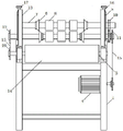
fig. 1 is a schematic side view of the present invention;
fig. 2 is a schematic top plan view of the present invention;
fig. 3 is a schematic rear plane structure diagram of the present invention;
fig. 4 is a schematic view of the side cross-section structure of the guide wheel of the present invention.
In the figure, the device comprises a frame 1, a frame 2, a lead-in frame 3, a coil frame 4, a motor 5, a mounting frame 6, an edge trimming knife 7, a knife roller shaft 8, a roller 9, a slide block 10, a gear 11, a chain wheel 12, a driving chain wheel 13, a coil rod 14, a transmission belt 15, a chain 16, an adjusting screw rod 17, an adjusting wheel 18, a clamping groove 19, a knife platform 20, a connecting platform 21, a clamping platform 22, a positioning screw hole 23, a bottom frame 24, a transmission roller 25, a baffle plate 26, an extension frame 27, a front roller 28 and a driven chain wheel.
Detailed Description
In the embodiment of fig. 1, 2, 3 and 4, an automatic trimming and winding machine for rubber films comprises a frame 1, a knife roll, a lead-in frame 2, a winding frame 3 and a motor 4, wherein the frame 1 is a hierarchical frame structure with a front end as a low end; the knife roll consists of an upper knife roll and a lower knife roll and comprises an installation frame 5, a knife roll shaft 7, a trimming knife 6 and a roller wheel 8, the installation frame 5 consists of two frame-type structures with an upper cross beam, the installation frame 5 is connected to the left side and the right side of the high end of the rack 1, the upper knife roll shaft 7 and the lower knife roll shaft 7 are respectively installed between the two installation frames 5 through a slide block 9 and a bearing, extension ends are respectively arranged on the outer sides of the installation frames 5, the extension ends on one side are connected into a vertical synchronous structure through a gear 10 in a matching way, a chain wheel 11 is installed outside the gear 10 at the extension end of the lower knife roll shaft 7, a driving chain wheel 12 is installed on the extension shaft on the other side; the trimming knife 6 is of a knife flywheel structure with a shaft hole and consists of four trimming knives symmetrically arranged at two ends of an upper knife roll shaft 7 and a lower knife roll shaft 7; the roller 8 is a non-metal section wheel and consists of at least six cutter roll shafts 7 symmetrically arranged between the trimming cutters 6, the lead-in frame 2 is a conduction roller frame for bearing the film of the previous process and is arranged in front of the cutter roll, the winding frame 3 is a film winding mechanism and is of a transmission belt 14 structure with a winding rod 13, the transmission belt 14 is connected with a driving chain wheel 12 through a chain 15, and the motor 4 is arranged in the frame 1 and is connected with the chain wheel 11 through the chain 15.
The mounting frame 5 is provided with a screw rod adjuster, the middle of the upper cross beam is provided with an upper through adjusting screw hole and a lower through adjusting screw hole, the screw rod adjuster comprises an adjusting screw rod 16 and an adjusting wheel 17, the lower end of the adjusting screw rod 16 is connected to the upper surface of the sliding block 9 through the adjusting screw hole, and the adjusting wheel 17 is connected to the upper end of the adjusting screw rod 16.
The round surface of the knife roll shaft 7 is provided with a sunken clamping groove 18 which runs through the two ends, the upper surface and one side of the upper knife roll are respectively provided with a movable safety cover and a safety switch, and the safety cover touches the safety switch to switch on the power supply when buckled.
The trimming knife 6 further comprises a knife platform 19, a connecting platform 20 and a clamping platform 21, the knife platform 19 is formed by a circular plane knife edge surface which contracts and extends to form a conical body on the back surface, the connecting platform 20 extends to form a cylinder at the contraction end of the knife platform 19, the clamping platform 21 is of a connecting key structure and extends between two ends in a shaft hole, the knife platform 19, the connecting platform 20 and the clamping platform 21 are of an integrated structure, the trimming knife 6 is connected with the knife roller shaft 7 through the shaft hole and clamped in the clamping groove 18 through the clamping platform 21, the trimming knife 6 is further positioned on the knife roller shaft 7 through a positioning screw hole 22 in the connecting platform 20, and the knife edge surfaces of the trimming knives 6 are oppositely arranged between the upper knife roller shaft 7 and the lower knife roller shaft 7.
The leading-in frame 2 comprises a bottom frame 23, a conducting roller 24 and a baffle 25, wherein the bottom frame 23 is of a derrick structure comprising a front cross beam and a rear cross beam, the front cross beam and the rear cross beam are obliquely connected between the front edge of the frame 1 and the knife roller, connecting grooves are formed in two ends of the front cross beam and the rear cross beam, the conducting roller 24 is composed of at least four parts arranged between two sides of the bottom frame 23, and the baffle 25 is a baffle plate for guiding a film moving track and is composed of two connecting grooves arranged on two sides.
The coil holder 3 further comprises an extension frame 26, a front roller 27 and a rear roller, wherein the front edge of the extension frame 26 is connected to two sides of the rear edge of the frame 1, the rear end of the extension frame extends towards the frame 1 in the far direction, the front roller 27 and the rear roller are respectively arranged at the front end and the rear end of the extension frame 26, the shaft of the front roller 27 is provided with an extension shaft and a driven sprocket 28 at one side of the extension frame, and the driven sprocket 28 is connected with the driving sprocket 11 through a chain 15.
The winding rod 13 is composed of two square three-side pipes, the lower end of the winding rod is connected with two side edges of the rear end of the extending frame 26, and the opening edges of the connected winding rod 13 are opposite and the upper end of the winding rod inclines forwards.
Example 1: according to the requirements of the thickness and trimming width parameters of an input film, the distance between the upper knife roller shaft 7 and the lower knife roller shaft 7 and the distance between the trimming knives 6 at the two ends of the upper knife roller shaft 7 and the lower knife roller shaft 7 and the baffle 25 on the leading-in frame 2 are adjusted through the adjusting wheel 17, and then the trimming coiler is started.
Example 2: the film fed in the previous process is manually led between an upper roller 8 and a lower roller 8 on a roller shaft 7 of the upper knife and the lower knife, the film is clamped by the rollers 8 and is pulled backwards, the edge of the film at the width part of the trimming knife 6 exceeds, the film is cut by the circular plane knife edges of the upper trimming knife 6 and the lower trimming knife 6 and is separated from the film, the film in front of the knife roll falls between two baffles 25 on a transmission roller 24 of the leading-in frame 2 under the action of gravity, and the film is continuously moved towards the knife roll along the transmission roller 24 between the two baffles 25 along with the continuous rotation traction of the knife roll.
Example 3: the film trimmed and leaving the knife roll falls onto the conveyor belt 14 above the film holder 3 and moves back along the conveyor belt 14. When the film needs to be rolled into a material roll for transmission, the film head is rolled onto the material roll shaft to form an initial film bundle after the material roll shaft rod is manually arranged in the opposite notch between the two material roll rods 13. The initial film bundle contacts the upper surface of the transmission belt 14 due to the lower surface, the backward kinetic energy of the transmission belt 14 pushes the film bundle to rotate, the output film is continuously wound by the rotating film bundle, and the film is manually cut off and the film bundle is folded up and the actions are repeated until the film bundle reaches a certain size.
Claims (7)
1. The utility model provides an automatic deburring stock winder of rubber film, comprises frame, break roll, leading-in frame, coil stock frame and motor, characterized by: the rack is a hierarchical frame structure with the front end as the low end; the knife roll consists of an upper knife roll and a lower knife roll and comprises an installation frame, a knife roll shaft, a trimming knife and a roller wheel, the installation frame consists of two frame-type structures with an upper cross beam, the installation frame is connected to the left side and the right side of the high end of the rack, the upper knife roll shaft and the lower knife roll shaft are respectively installed between the two installation frames through a slider and a bearing, extension ends are arranged on the outer sides of the installation frames, the extension ends on one side are connected into a vertical synchronous structure through gears in an inosculating manner, a chain wheel is installed outside the gears at the extension end of the lower knife roll shaft, a driving chain wheel is installed on the extension shaft on the other side, and; the trimming knife is of a knife flywheel structure with a shaft hole and consists of four parts which are symmetrically arranged at two ends of an upper knife roll shaft and a lower knife roll shaft; the roller is a non-metal section wheel and consists of at least six cutter roll shafts symmetrically arranged between the trimming cutters, the leading-in frame is a conduction roller frame for receiving the film of the previous process and is arranged in front of the cutter roll, the winding frame is a film winding mechanism and is a transmission belt structure with a winding rod, the transmission belt is connected with a driving sprocket through a chain, and the motor is arranged in the frame and is connected with the sprocket through the chain.
2. The automatic trimming winder for rubber film according to claim 1, wherein: the mounting bracket on install screw rod regulator and the centre of entablature have penetrating regulation screw from top to bottom, the screw rod regulator includes adjusting screw and regulating wheel, adjusting screw's lower extreme is connected on the slider through adjusting the screw, the upper end at adjusting screw is connected to the regulating wheel.
3. The automatic trimming winder for rubber film according to claim 1, wherein: the round surface of the knife roll shaft is provided with a sunken clamping groove penetrating through two ends, the upper surface and one side of the upper knife roll are respectively provided with a movable safety cover and a safety switch, and the safety cover is buckled to touch the safety switch to switch on a power supply.
4. The automatic trimming winder for rubber film according to claim 1, wherein: the trimming knife is characterized by further comprising a knife platform, a connecting platform and a clamping platform, wherein the knife platform is formed by a circular plane knife edge surface which is contracted and extended into a conical body on the back surface, the connecting platform is extended into a cylinder at the contraction end of the knife platform, the clamping platform is of a connecting key structure and extends between two ends in a shaft hole, the knife platform, the connecting platform and the clamping platform are of an integrated structure, the trimming knife is connected with the knife roll shaft through the shaft hole and is clamped in the clamping groove in a clamping manner, the trimming knife is positioned on the knife roll shaft through a positioning screw hole in the connecting platform, and the knife edge surfaces of the trimming knife are oppositely arranged between the upper knife roll shaft and the lower knife roll.
5. The automatic trimming winder for rubber film according to claim 1, wherein: the leading-in frame including chassis, conduction roller and baffle, the chassis is connected between the preceding of frame and rotor for the derrick structure and the slope including front and back crossbeam in, there is the spread groove at the both ends of front and back crossbeam, the conduction roller comprises at least four of installing between the chassis both sides, the baffle is for the striker plate of guide film movement track and constitute by installing two of front and back crossbeam both sides spread groove.
6. The automatic trimming winder for rubber film according to claim 1, wherein: the coil material frame still including extending frame, preceding roller and back roller, the preceding both sides and the rear end of connecting in the frame back limit of extending frame extend with the distant place to the frame, preceding roller and back roller are installed respectively at the front end and the rear end of extending the frame and preceding roller axle has extension axle and driven sprocket in extension frame one side, driven sprocket passes through the chain and connects drive sprocket.
7. The automatic trimming winder for rubber film according to claim 1, wherein: the coiling rod is composed of two square three-side pipes, the lower end of the coiling rod is connected with two side edges of the rear end of the extending frame, the opening edges of the connected coiling rod face to each other, and the upper end of the coiling rod inclines forwards.
Priority Applications (1)
| Application Number | Priority Date | Filing Date | Title |
|---|---|---|---|
| CN202020285103.8U CN211891029U (en) | 2020-03-10 | 2020-03-10 | Automatic trimming and winding machine for rubber films |
Applications Claiming Priority (1)
| Application Number | Priority Date | Filing Date | Title |
|---|---|---|---|
| CN202020285103.8U CN211891029U (en) | 2020-03-10 | 2020-03-10 | Automatic trimming and winding machine for rubber films |
Publications (1)
| Publication Number | Publication Date |
|---|---|
| CN211891029U true CN211891029U (en) | 2020-11-10 |
Family
ID=73322229
Family Applications (1)
| Application Number | Title | Priority Date | Filing Date |
|---|---|---|---|
| CN202020285103.8U Active CN211891029U (en) | 2020-03-10 | 2020-03-10 | Automatic trimming and winding machine for rubber films |
Country Status (1)
| Country | Link |
|---|---|
| CN (1) | CN211891029U (en) |
-
2020
- 2020-03-10 CN CN202020285103.8U patent/CN211891029U/en active Active
Similar Documents
| Publication | Publication Date | Title |
|---|---|---|
| CN2885530Y (en) | Highly efficient sizing material stripping-cutting machine | |
| CN111232729A (en) | Corrugated board trimming and collecting equipment and production process using same | |
| CN211762744U (en) | Strip cutting and dicing cutter for rubber sheet rubber | |
| CN206227563U (en) | A kind of adjustable sugar sweet preforming device of sheeting thickness | |
| CN211891029U (en) | Automatic trimming and winding machine for rubber films | |
| CN101104240B (en) | Air valve locking fastener automatic forming machine | |
| CN115257020B (en) | Automatic production line for extrusion, molding, conveying and cutting of GPPS (general purpose polystyrene) plates | |
| CN115972529A (en) | Multilayer co-extrusion casting film production device and production process thereof | |
| CN110976628A (en) | Full-automatic stainless steel pull ring forming process and forming system thereof | |
| CN114055600B (en) | Processing method of micro-foaming SPC wallboard | |
| CN113547683B (en) | Automatic hot-press forming production equipment and method for rubber | |
| CN203888060U (en) | Cutting device used for plastic film rim charge recycling system | |
| CN210189968U (en) | Upper compression roller adjusting mechanism of granulator | |
| CN113843848A (en) | Continuous stretching rotary-cut die for processing automobile parts | |
| CN212826833U (en) | Automatic film-coating winding machine for rubber cooling film stock | |
| CN214455639U (en) | Automatic blanking and leftover material winding machine of film production punch press | |
| CN215202253U (en) | Antiseized cutting device of cooling of rubber masterbatch piece | |
| CN219705747U (en) | Online strake slitting granulator of plastic-aluminum board production line | |
| CN215550085U (en) | Raw rubber strip production line for feeding of rubber injection molding machine | |
| CN218614270U (en) | Guillootine is used in glass film production | |
| CN212218944U (en) | Rubber film stock cooling cuts automatic operation device | |
| CN219095829U (en) | XPE master slice cooling traction all-in-one | |
| CN216067597U (en) | Strip cutting mechanism of vulcanizing machine | |
| CN2174316Y (en) | Rubber hold-down calendering forming machine | |
| CN219971382U (en) | Edge cutting device of bubble film machine |
Legal Events
| Date | Code | Title | Description |
|---|---|---|---|
| GR01 | Patent grant | ||
| GR01 | Patent grant |