Double-vibration control box for wolfberry fruit vibration picking machine
Technical Field
The utility model belongs to the technical field of the control box, especially, relate to matrimony vine vibration picking machine is with two control boxes that shake.
Background
Fructus Lycii is plant of genus Lycium of family Solanaceae. The Chinese wolfberry is a general name of the Chinese wolfberry species such as commercial Chinese wolfberry, plant Ningxia Chinese wolfberry, Chinese wolfberry and the like. The wolfberry fruits which are edible and medicinal in daily life are the fruits of Ningxia wolfberry fruit which is the only one loaded in Chinese pharmacopoeia 2010 edition, and the wolfberry fruit has the functions of improving the immunity of the organism, tonifying qi and strengthening essence, nourishing the liver and kidney, resisting aging, stopping thirst, warming the body and resisting tumors. Has effects of lowering blood pressure, blood lipid and blood sugar, preventing atherosclerosis, protecting liver, resisting fatty liver, and promoting liver cell regeneration. Every season of harvesting the medlar, a plurality of types of medlar picking machines can be used for picking the medlar instead of manpower.
The current matrimony vine picking machine mostly adopts two modes of shaking, because it is great to pick work load, the control end of matrimony vine picking machine mostly needs to install in the control box, and most current control boxes are internal with power equipment installation in the cabinet, because be in relatively inclosed space for a long time, the internal humidity of cabinet is difficult for discharging, and under the condition of hot comparison, the moisture can be more serious, moisture gathering is many later on and is formed the water droplet and fall, cause the short circuit phenomenon to electrical equipment, influence the use, and under long-time powerful operating condition, the radiating effect does not want yet, there is not little influence to electrical equipment's work efficiency and life.
SUMMERY OF THE UTILITY MODEL
Technical problem to be solved
The utility model aims at solving among the prior art and under long-time powerful operating condition, the radiating effect does not want yet, has the shortcoming that influence exists not little to electrical equipment's work efficiency and life, and the matrimony vine vibration picker that proposes is with two control boxes that vibrate.
(II) technical scheme
In order to achieve the above purpose, the utility model adopts the following technical scheme: the double-vibration control box for the wolfberry vibration picking machine comprises a box body, wherein a ventilation mechanism is arranged in the box body and comprises a third fixing rod, the third fixing rod is fixedly connected to the inner side wall of the box body, the top of the third fixing rod is rotatably connected with a driving shaft, the outer surface of the driving shaft is fixedly connected with a first connecting rod, one end, away from the driving shaft, of the first connecting rod is rotatably connected with a first sliding block, the bottom of the third fixing rod is rotatably connected with a rotating shaft, the outer surface of the rotating shaft is rotatably connected with a transmission rod, the transmission rod penetrates through the first sliding block and is in sliding connection with the first sliding block, the outer side wall of one end, away from the rotating shaft, of the transmission rod is fixedly connected with a plurality of first fixing rods, one end, close to the rotating shaft, of the, the inner bottom of the box body is fixedly connected with a limiting plate, and the second sliding block is connected inside the limiting plate in a sliding mode.
As a further description of the above technical solution:
the inside of box is provided with the mounting panel, the mounting panel respectively with the interior top and interior bottom fixed connection of box.
As a further description of the above technical solution:
the ventilation mechanism has two, two ventilation mechanism is located the both sides of mounting panel respectively.
As a further description of the above technical solution:
the utility model discloses a solar energy water heater, including the installation case, the back lateral wall fixed mounting of box has the install bin, the lateral wall fixedly connected with motor of install bin, the drive end of motor runs through the lateral wall of install bin and extends to its inside and fixedly connected with actuating lever, the outer fixed surface cover of actuating lever is equipped with two drive gear.
As a further description of the above technical solution:
two wherein one end of the drive shaft among the ventilation mechanism all is connected through the bearing and the inside wall rotation of box, two wherein the other end of drive shaft all runs through the inside and the fixedly connected with drive gear that the lateral wall of box extended to the install bin, two drive gear is connected with two drive gear meshing respectively.
As a further description of the above technical solution:
the first dead lever is kept away from the one end fixedly connected with first stopper of transfer line, the surface of first stopper rotates and is connected with a plurality of first flabellums.
As a further description of the above technical solution:
the top fixedly connected with stock of second slider, the surface fixedly connected with a plurality of second dead levers of stock, the surface of second dead lever rotates and is connected with a plurality of second flabellums.
As a further description of the above technical solution:
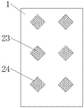
the positive lateral wall of box is provided with the installation door, the lateral wall fixedly connected with handle of installation door, a plurality of ventilation holes have been seted up to the lateral wall of box, and is a plurality of the inside in ventilation hole all is provided with the dust screen.
As a further description of the above technical solution:
the limiting plate is internally provided with a movable groove corresponding to the second sliding block, and the second sliding block is connected inside the movable groove in a sliding manner.
The utility model discloses following beneficial effect has: this matrimony vine vibration picking machine is with two control boxes that shake, when using, through drive shaft, first connecting rod, transfer line, second connecting rod, first slider, second slider, limiting plate, movable groove, first flabellum, second flabellum, ventilation hole, the dust screen that sets up, can follow the inside and outside air flow of the effectual acceleration control box of multidirectional, play better heat dissipation dehumidification effect, easy operation has certain practicality.
Drawings
Fig. 1 is a schematic view of the overall structure of the present invention;
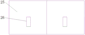
fig. 2 is a front view of the present invention;
FIG. 3 is a schematic view of the connection relationship between the installation box and the box body of the present invention;
fig. 4 is a side view of the present invention.
Illustration of the drawings:
1. a box body; 2. mounting a plate; 3. a drive shaft; 4. a first fan blade; 5. a first fixing lever; 6. a first link; 7. a first stopper; 8. a first slider; 9. a transmission rod; 10. a rotating shaft; 11. a second link; 12. a movable groove; 13. a limiting plate; 14. a second slider; 15. a second fan blade; 16. a second fixing bar; 17. a long rod; 18. a motor; 19. a transmission gear; 20. installing a box; 21. a drive rod; 22. a drive gear; 23. a dust screen; 24. a vent hole; 25. installing a door; 26. a handle; 27. and a third fixing rod.
Detailed Description
The technical solutions in the embodiments of the present invention will be described clearly and completely with reference to the accompanying drawings in the embodiments of the present invention, and it is obvious that the described embodiments are only some embodiments of the present invention, not all embodiments. Based on the embodiments in the present invention, all other embodiments obtained by a person skilled in the art without creative work belong to the protection scope of the present invention.
In the description of the present invention, it should be noted that the terms "center", "upper", "lower", "left", "right", "vertical", "horizontal", "inner", "outer", and the like indicate orientations or positional relationships based on the orientations or positional relationships shown in the drawings, and are only for convenience of description and simplification of description, but do not indicate or imply that the device or element referred to must have a specific orientation, be constructed and operated in a specific orientation, and thus, should not be construed as limiting the present invention; the terms "first," "second," and "third" are used for descriptive purposes only and are not to be construed as indicating or implying relative importance, and furthermore, unless otherwise explicitly stated or limited, the terms "mounted," "connected," and "connected" are to be construed broadly and may be, for example, fixedly connected, detachably connected, or integrally connected; can be mechanically or electrically connected; they may be connected directly or indirectly through intervening media, or they may be interconnected between two elements. The specific meaning of the above terms in the present invention can be understood in specific cases to those skilled in the art.
Referring to fig. 1-4, the present invention provides an embodiment: the double-vibration control box for the wolfberry vibration picking machine comprises a box body 1, a ventilation mechanism is arranged inside the box body 1, the ventilation mechanism comprises a third fixing rod 27, the third fixing rod 27 is fixedly connected to the inner side wall of the box body 1, the top of the third fixing rod 27 is rotatably connected with a driving shaft 3, the outer surface of the driving shaft 3 is fixedly connected with a first connecting rod 6, one end of the first connecting rod 6, which is far away from the driving shaft 3, is rotatably connected with a first sliding block 8, the bottom of the third fixing rod 27 is rotatably connected with a rotating shaft 10, the outer surface of the rotating shaft 10 is rotatably connected with a transmission rod 9, the transmission rod 9 penetrates through the first sliding block 8 and is slidably connected with the first sliding block, the outer side wall of one end, which is far away from the rotating shaft 10, of the transmission rod 9 is fixedly connected with a plurality of first fixing rods 5, a limiting plate 13 is fixedly connected to the inner bottom of the box body 1, and a second sliding block 14 is slidably connected to the inner portion of the limiting plate 13.
The mounting plate 2 is arranged in the box body 1, and the mounting plate 2 is fixedly connected with the inner top and the inner bottom of the box body 1 respectively so as to be convenient for mounting corresponding electrical elements; the two ventilation mechanisms are respectively positioned on two sides of the mounting plate 2, so that the ventilation efficiency is improved; the rear side wall of the box body 1 is fixedly provided with a mounting box 20, the side wall of the mounting box 20 is fixedly connected with a motor 18, the driving end of the motor 18 penetrates through the side wall of the mounting box 20 to extend into the mounting box and is fixedly connected with a driving rod 21, and the outer surface of the driving rod 21 is fixedly sleeved with two driving gears 22, so that power transmission is facilitated; one end of each of the driving shafts 3 in the two ventilation mechanisms is rotatably connected with the inner side wall of the box body 1 through a bearing, the other end of each of the two driving shafts 3 penetrates through the side wall of the box body 1 to extend into the installation box 20 and is fixedly connected with a transmission gear 19, and the two transmission gears 19 are respectively meshed with the two driving gears 22 to be connected with the ventilation mechanisms, so that energy is saved, and one power source is used for driving the two ventilation mechanisms; one end of the first fixing rod 5, which is far away from the transmission rod 9, is fixedly connected with a first limiting block 7, and the outer surface of the first limiting block 7 is rotatably connected with a plurality of first fan blades 4 to provide a longitudinal ventilation effect; a long rod 17 is fixedly connected to the top of the second slider 14, a plurality of second fixing rods 16 are fixedly connected to the outer surface of the long rod 17, and a plurality of second fan blades 15 are rotatably connected to the outer surface of the second fixing rods 16 to provide a transverse ventilation effect; the front side wall of the box body 1 is provided with a mounting door 25, the outer side wall of the mounting door 25 is fixedly connected with a handle 26, the outer side wall of the box body 1 is provided with a plurality of ventilation holes 24, dust screens 23 are arranged inside the ventilation holes 24, and the ventilation mechanism is matched to accelerate the air exchange rate inside and outside the box body 1; the inside of the limiting plate 13 is provided with a movable groove 12 corresponding to the second slider 14, and the second slider 14 is slidably connected inside the movable groove 12 to provide a certain position space for the sliding of the second slider 14.
The working principle is as follows: when the double-vibration control box for the wolfberry fruit vibration picking machine is used, the mounting door 25 is opened, corresponding electrical components are mounted on the mounting plate 2, when picking operation is carried out, the motor 18 is started, the driving end of the motor 18 drives the driving gear 22 to rotate, the transmission gear 19 meshed and connected with the driving gear 22 rotates along with the driving gear 22, the transmission gear 19 drives the driving shaft 3 to rotate, the first connecting rod 6 fixedly connected to the outer surface of the driving shaft 3 rotates around the driving shaft 3, the first sliding block 8 rotationally connected with the first connecting rod 6 drives the transmission rod 9 to do reciprocating rotation around the rotating shaft 10 during movement, a good air blowing effect is achieved by matching the first fixing rod 5 and the first fan blade 4, when the transmission rod 9 rotates, the second sliding block 14 does reciprocating movement in the horizontal direction under the limiting effect of the limiting plate 13, and the second fan blade 15 arranged above the second sliding block plays a transverse air blowing effect, the cooperation sets up in box 1 lateral wall side ventilation hole 24, can accelerate the inside and outside gas exchange of box 1, reaches better heat dissipation dehumidification effect, has better guard action to the electrical components of installing on mounting panel 2, has certain practicality.
Finally, it should be noted that: although the present invention has been described in detail with reference to the foregoing embodiments, it will be apparent to those skilled in the art that modifications and variations can be made in the embodiments or in part of the technical features of the embodiments without departing from the spirit and the scope of the invention.