CN112510500A - Outdoor power distribution cabinet for factory electrical control system - Google Patents
Outdoor power distribution cabinet for factory electrical control system Download PDFInfo
- Publication number
- CN112510500A CN112510500A CN202011348299.1A CN202011348299A CN112510500A CN 112510500 A CN112510500 A CN 112510500A CN 202011348299 A CN202011348299 A CN 202011348299A CN 112510500 A CN112510500 A CN 112510500A
- Authority
- CN
- China
- Prior art keywords
- power distribution
- distribution cabinet
- cabinet body
- rotating shaft
- pipe
- Prior art date
- Legal status (The legal status is an assumption and is not a legal conclusion. Google has not performed a legal analysis and makes no representation as to the accuracy of the status listed.)
- Withdrawn
Links
Images


Classifications
-
- H—ELECTRICITY
- H02—GENERATION; CONVERSION OR DISTRIBUTION OF ELECTRIC POWER
- H02B—BOARDS, SUBSTATIONS OR SWITCHING ARRANGEMENTS FOR THE SUPPLY OR DISTRIBUTION OF ELECTRIC POWER
- H02B1/00—Frameworks, boards, panels, desks, casings; Details of substations or switching arrangements
- H02B1/26—Casings; Parts thereof or accessories therefor
- H02B1/28—Casings; Parts thereof or accessories therefor dustproof, splashproof, drip-proof, waterproof or flameproof
-
- A—HUMAN NECESSITIES
- A62—LIFE-SAVING; FIRE-FIGHTING
- A62C—FIRE-FIGHTING
- A62C3/00—Fire prevention, containment or extinguishing specially adapted for particular objects or places
- A62C3/16—Fire prevention, containment or extinguishing specially adapted for particular objects or places in electrical installations, e.g. cableways
-
- H—ELECTRICITY
- H02—GENERATION; CONVERSION OR DISTRIBUTION OF ELECTRIC POWER
- H02B—BOARDS, SUBSTATIONS OR SWITCHING ARRANGEMENTS FOR THE SUPPLY OR DISTRIBUTION OF ELECTRIC POWER
- H02B1/00—Frameworks, boards, panels, desks, casings; Details of substations or switching arrangements
- H02B1/26—Casings; Parts thereof or accessories therefor
- H02B1/30—Cabinet-type casings; Parts thereof or accessories therefor
- H02B1/306—Accessories, e.g. windows
-
- H—ELECTRICITY
- H02—GENERATION; CONVERSION OR DISTRIBUTION OF ELECTRIC POWER
- H02B—BOARDS, SUBSTATIONS OR SWITCHING ARRANGEMENTS FOR THE SUPPLY OR DISTRIBUTION OF ELECTRIC POWER
- H02B1/00—Frameworks, boards, panels, desks, casings; Details of substations or switching arrangements
- H02B1/26—Casings; Parts thereof or accessories therefor
- H02B1/30—Cabinet-type casings; Parts thereof or accessories therefor
- H02B1/32—Mounting of devices therein
-
- H—ELECTRICITY
- H02—GENERATION; CONVERSION OR DISTRIBUTION OF ELECTRIC POWER
- H02B—BOARDS, SUBSTATIONS OR SWITCHING ARRANGEMENTS FOR THE SUPPLY OR DISTRIBUTION OF ELECTRIC POWER
- H02B1/00—Frameworks, boards, panels, desks, casings; Details of substations or switching arrangements
- H02B1/26—Casings; Parts thereof or accessories therefor
- H02B1/50—Pedestal- or pad-mounted casings; Parts thereof or accessories therefor
- H02B1/505—Pedestal- or pad-mounted casings; Parts thereof or accessories therefor retractable installations
-
- H—ELECTRICITY
- H02—GENERATION; CONVERSION OR DISTRIBUTION OF ELECTRIC POWER
- H02B—BOARDS, SUBSTATIONS OR SWITCHING ARRANGEMENTS FOR THE SUPPLY OR DISTRIBUTION OF ELECTRIC POWER
- H02B1/00—Frameworks, boards, panels, desks, casings; Details of substations or switching arrangements
- H02B1/56—Cooling; Ventilation
- H02B1/565—Cooling; Ventilation for cabinets
-
- H—ELECTRICITY
- H02—GENERATION; CONVERSION OR DISTRIBUTION OF ELECTRIC POWER
- H02J—CIRCUIT ARRANGEMENTS OR SYSTEMS FOR SUPPLYING OR DISTRIBUTING ELECTRIC POWER; SYSTEMS FOR STORING ELECTRIC ENERGY
- H02J7/00—Circuit arrangements for charging or depolarising batteries or for supplying loads from batteries
- H02J7/34—Parallel operation in networks using both storage and other dc sources, e.g. providing buffering
- H02J7/35—Parallel operation in networks using both storage and other dc sources, e.g. providing buffering with light sensitive cells
-
- Y—GENERAL TAGGING OF NEW TECHNOLOGICAL DEVELOPMENTS; GENERAL TAGGING OF CROSS-SECTIONAL TECHNOLOGIES SPANNING OVER SEVERAL SECTIONS OF THE IPC; TECHNICAL SUBJECTS COVERED BY FORMER USPC CROSS-REFERENCE ART COLLECTIONS [XRACs] AND DIGESTS
- Y02—TECHNOLOGIES OR APPLICATIONS FOR MITIGATION OR ADAPTATION AGAINST CLIMATE CHANGE
- Y02P—CLIMATE CHANGE MITIGATION TECHNOLOGIES IN THE PRODUCTION OR PROCESSING OF GOODS
- Y02P90/00—Enabling technologies with a potential contribution to greenhouse gas [GHG] emissions mitigation
- Y02P90/50—Energy storage in industry with an added climate change mitigation effect
Landscapes
- Engineering & Computer Science (AREA)
- Power Engineering (AREA)
- Health & Medical Sciences (AREA)
- Public Health (AREA)
- Business, Economics & Management (AREA)
- Emergency Management (AREA)
- Patch Boards (AREA)
Abstract
An outdoor power distribution cabinet for a factory electrical control system comprises a power distribution cabinet body; the bottom of the power distribution cabinet body is provided with a floating seat which is pressed on the bottom plate; first vent holes are formed in two sides of the cabinet body of the power distribution cabinet, and connecting boxes are arranged on two sides of the interior of the cabinet body of the power distribution cabinet; the third rotating shaft is provided with a fan blade; a fourth rotating shaft is arranged on two sides inside the fixed box; the sealing plates are arranged on two sides of the cabinet body of the power distribution cabinet, and second vent holes are formed in the sealing plates; a fixed rod is arranged in the fixed box and is inserted into the connecting cylinder; a rack is arranged on the connecting cylinder, a gear is arranged on the fourth rotating shaft, and the gear is meshed with the rack; the connecting cylinder is provided with a connecting rod which is connected with the sealing plate; a gas distribution disc and a gas collection disc are arranged in the cold water tank, and the heat conduction pipe is communicated with the gas distribution disc and the gas collection disc; the air extractor is provided with an air extraction pipe and an air delivery pipe; the gas collecting disc is provided with an exhaust pipe. The multifunctional heat dissipation device has various functions, not only has excellent heat dissipation effect, but also can effectively prevent rainwater or accumulated water from entering, and has excellent use effect.
Description
Technical Field
The invention relates to the technical field of power distribution cabinets, in particular to an outdoor power distribution cabinet for a factory electrical control system.
Background
The power distribution cabinet is divided into a power distribution cabinet, a lighting distribution cabinet and a metering cabinet, and is a final-stage device of a power distribution system, and the power distribution cabinet is used in occasions with dispersed loads and less loops; they distribute the power of a certain circuit of the upper-level power distribution equipment to the nearby loads, and the equipment provides protection, monitoring and control for the loads; the utility model discloses a portable outdoor switch board is disclosed in chinese utility model patent with publication number CN204732707U, including the cabinet body and the division board arranged at the top of the cabinet body, the division board includes a conical baffle, the both sides of baffle are equipped with a "L" shaped diversion bend respectively, the inboard of diversion bend forms a diversion passageway respectively, the baffle is equipped with solar cell panel, solar cell panel is connected with the battery, the cabinet body is equipped with the single leaf door, the single leaf door is equipped with the fingerprint lock, the internal top of cabinet is equipped with the camera, the camera is connected with the battery, the bottom of the cabinet body is equipped with the universal wheel, the both sides of the cabinet body are equipped with fixing device, the fixing device includes the guide pile, adjusting screw and sliding sleeve, the technical scheme effectively prevents its slip through the fixing device, adopt fingerprint lock and camera, make the switch board outdoor safer; but it dispels the heat through heat dissipation shutter and heat dissipation stick in specific use, and radiating effect and radiating efficiency are not good to when raining, rainwater and ground ponding get into switch board cabinet body 1 easily in, bring the harm to the internals easily, wait to improve.
Disclosure of Invention
Objects of the invention
In order to solve the technical problems in the background art, the invention provides the outdoor power distribution cabinet for the factory electrical control system, which has various functions, not only has excellent heat dissipation effect, but also can effectively prevent rainwater or accumulated water from entering, and has excellent use effect.
(II) technical scheme
The invention provides an outdoor power distribution cabinet for a factory electrical control system, which comprises a power distribution cabinet body, a bottom plate, a connecting piece, a fixed box, a sealing plate, a double-shaft motor, a third rotating shaft, a driving belt, a connecting cylinder, a cold water tank, a heat conducting pipe and a central processing unit, wherein the bottom plate is fixedly connected with the power distribution cabinet body;
a power distribution cabinet door is arranged on the power distribution cabinet body, a floating seat is arranged at the bottom of the power distribution cabinet body, the interior of the floating seat is hollow, and the floating seat is pressed on the bottom plate; a guide piece is vertically arranged on the bottom plate, a limiting piece is arranged at the top end of the guide piece, and the connecting piece is arranged on the cabinet body of the power distribution cabinet and is in sliding connection with the guide piece; first vent holes are formed in two sides of the cabinet body of the power distribution cabinet, connecting boxes are vertically arranged on two sides of the interior of the cabinet body of the power distribution cabinet, the connecting boxes cover the first vent holes, and third vent holes are formed in one sides, back to the first vent holes, of the connecting boxes; the double-shaft motor is arranged in the power distribution cabinet body, and two output ends of the double-shaft motor are provided with first rotating shafts; a second rotating shaft is vertically arranged on the connecting box, and the first rotating shaft is in transmission connection with the second rotating shaft; the number of the third rotating shafts is multiple, the third rotating shafts are rotatably connected with the connecting box, and the second rotating shafts are in transmission connection with the third rotating shafts; the third rotating shaft is provided with fan blades, and the blowing directions of the fan blades on the two sides are the same;
the fixed box is arranged on the cabinet body of the power distribution cabinet, fourth rotating shafts are longitudinally arranged on two sides inside the fixed box, and the two fourth rotating shafts are in transmission connection through a transmission belt; a driving motor is arranged in the fixed box, and the output end of the driving motor is connected with one group of fourth rotating shafts; the sealing plates are vertically arranged on two sides of the cabinet body of the power distribution cabinet, and second vent holes corresponding to the first vent holes are formed in the sealing plates; two groups of connecting cylinders are vertically arranged and extend upwards into the fixed box, fixed rods are arranged in the fixed box and inserted into the connecting cylinders; a rack is vertically arranged on the connecting cylinder, a gear is arranged on the fourth rotating shaft, and the gear is meshed with the rack; the connecting cylinder is provided with a connecting rod, and the other end of the connecting rod is connected with the sealing plate;
the cold water tank is arranged on the fixed tank, the cold water tank is internally provided with a gas distribution disc and a gas collection disc, and the heat conduction pipes are in multiple groups and are communicated with the gas distribution disc and the gas collection disc; an air pump is arranged on the fixed box, an air exhaust pipe and an air delivery pipe are arranged on the air pump, the other end of the air exhaust pipe extends into the bottom end of the interior of the cabinet body of the power distribution cabinet, and the air delivery pipe is communicated with the air distribution disc; the air collecting disc is provided with an exhaust pipe, and the other end of the exhaust pipe extends into the top end of the inside of the cabinet body of the power distribution cabinet;
a temperature sensor is arranged in the power distribution cabinet body, and a rainwater sensor is arranged at the top of the fixed box; the central processing unit is in communication connection with the temperature sensor and the rainwater sensor, and is in control connection with the double-shaft motor, the driving motor and the air extractor.
Preferably, the first rotating shaft is provided with a bevel gear, the second rotating shaft is provided with a bevel gear, and the two bevel gears are meshed and connected; and each third rotating shaft is provided with a bevel gear, the second rotating shaft is correspondingly provided with a bevel gear, and each third rotating shaft is meshed and connected with the second rotating shaft through the bevel gear.
Preferably, the cabinet body of the power distribution cabinet is internally provided with a moisture absorption box and a humidity sensor, and the humidity sensor is in communication connection with the central processing unit.
Preferably, a first limit switch and a second limit switch are arranged on the cabinet body of the power distribution cabinet, the first limit switch is positioned above the sealing plate, and the second limit switch is positioned below the sealing plate; the first limit switch is connected with the driving motor in a control mode, and the second limit switch is connected with the driving motor in a control mode.
Preferably, the device also comprises a fixing nail; the bottom plate is provided with a connecting plate, the connecting plate is provided with a through hole for the fixing nail to pass through, and the fixing nail fixes the connecting plate.
Preferably, the fixing box is provided with a solar power generation panel and a storage battery, and the solar power generation panel is electrically connected with the storage battery.
Preferably, a dust filter net is vertically arranged in the connecting box and covers the first vent hole.
Preferably, an inert gas storage tank is arranged in the fixed box, an inert gas output pipe is arranged on the inert gas storage tank, and the other end of the inert gas output pipe extends into the power distribution cabinet body.
Preferably, a control valve is arranged on the inert gas output pipe, and a smoke sensor is arranged in the cabinet body of the power distribution cabinet; the smoke sensor is in communication connection with the central processing unit, and the central processing unit is in control connection with the control valve.
Preferably, the heat conductive pipe is a spiral pipe made of aluminum alloy.
The technical scheme of the invention has the following beneficial technical effects:
when rainstorm occurs, the floating seat rises under the action of buoyancy, the guide piece plays a role in guiding, and the power distribution cabinet body rises along with the floating seat, so that accumulated water is effectively prevented from entering the power distribution cabinet body to cause damage of the power distribution cabinet body; the double-shaft motor rotates the second rotating shafts on the two sides through the first rotating shaft so as to drive the third rotating shafts to rotate, the fan blades rotate along with the second rotating shafts, the blowing directions of the fan blades on the two sides are the same, namely, the fan blades on one side blow external air into the cabinet body of the power distribution cabinet, and the fan blades on the other side discharge internal hot air, so that heat dissipation in the cabinet body of the power distribution cabinet is realized, and the heat dissipation efficiency and the heat dissipation effect are obviously improved;
when the rain sensor detects rain, the driving motor enables one group of the fourth rotating shafts to rotate, the driving belt drives the other group of the fourth rotating shafts to rotate, the gears on the two sides drive the corresponding racks to move in the vertical direction, the two connecting cylinders drive the two sealing plates to move in the vertical direction under the guiding action of the fixing rods, so that the second vent holes in the sealing plates are staggered with the first vent holes in the cabinet body of the power distribution cabinet, the first vent holes are sealed, and the effect of preventing rain from entering is achieved; during the gas distributor is taken out to the internal gas of switch board cabinet to the air extractor this moment, gaseous even dispersion goes into each heat pipe, and the cold water in the cold water tank absorbs the heat that gas contains, and the gas after the cooling gathers in the gas collector dish and arranges to switch board cabinet internally through the blast pipe to dispel the heat to the switch board cabinet is internal, excellent in use effect.
Drawings
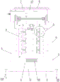
Fig. 1 is a schematic structural diagram of an outdoor power distribution cabinet for a factory electrical control system according to the present invention.
Fig. 2 is a front view of an outdoor power distribution cabinet for a plant electrical control system according to the present invention.
Fig. 3 is a schematic structural diagram of a fixed box in an outdoor power distribution cabinet for a factory electrical control system according to the present invention.
Fig. 4 is an enlarged view of a portion a of an outdoor power distribution cabinet for a factory electrical control system according to the present invention.
Fig. 5 is a schematic structural diagram of an intercooler tank in an outdoor power distribution cabinet for a factory electrical control system according to the present invention.
Fig. 6 is a system block diagram of an outdoor power distribution cabinet for a factory electrical control system according to the present invention.
Reference numerals: 1. a power distribution cabinet body; 2. a floating seat; 3. a base plate; 4. a guide member; 5. a connecting member; 6. a limiting member; 7. a fixed box; 8. a solar power panel; 9. a sealing plate; 10. a connecting rod; 11. a first vent hole; 12. a second vent hole; 13. a connecting box; 14. a third vent hole; 15. a double-shaft motor; 16. a first rotating shaft; 17. a second rotating shaft; 18. a fan blade; 19. a third rotating shaft; 20. a drive motor; 21. a fourth rotating shaft; 22. a transmission belt; 23. a gear; 24. a rack; 25. a connecting cylinder; 26. fixing the rod; 27. a cold water tank; 28. an air extractor; 29. an air exhaust pipe; 30. a gas delivery pipe; 31. an exhaust pipe; 32. an inert gas storage tank; 33. an inert gas output pipe; 34. a gas distribution plate; 35. a gas collecting tray; 36. a heat conducting pipe; 37. a cabinet door of a power distribution cabinet; 38. fixing nails; 39. a connecting plate; 40. a moisture-absorbing box; 41. a central processing unit; 42. a temperature sensor; 43. a smoke sensor; 44. a humidity sensor; 45. a first limit switch; 46. a second limit switch; 47. a control valve; 48. a rain sensor.
Detailed Description
In order to make the objects, technical solutions and advantages of the present invention more apparent, the present invention will be described in further detail with reference to the accompanying drawings in conjunction with the following detailed description. It should be understood that the description is intended to be exemplary only, and is not intended to limit the scope of the present invention. Moreover, in the following description, descriptions of well-known structures and techniques are omitted so as to not unnecessarily obscure the concepts of the present invention.
As shown in fig. 1-6, the outdoor power distribution cabinet for a factory electrical control system according to the present invention includes a power distribution cabinet body 1, a bottom plate 3, a connecting member 5, a fixing box 7, a sealing plate 9, a dual-axis motor 15, a third rotating shaft 19, a transmission belt 22, a connecting cylinder 25, a cold water tank 27, a heat pipe 36 and a central processor 41;
a power distribution cabinet door 37 is arranged on the power distribution cabinet body 1, a floating seat 2 is arranged at the bottom of the power distribution cabinet body 1, the interior of the floating seat 2 is hollow, and the floating seat 2 is pressed on the bottom plate 3; a guide part 4 is vertically arranged on the bottom plate 3, a limiting part 6 is arranged at the top end of the guide part 4, and a connecting part 5 is arranged on the power distribution cabinet body 1 and is in sliding connection with the guide part 4; first vent holes 11 are formed in two sides of a cabinet body 1 of the power distribution cabinet, connecting boxes 13 are vertically arranged on two sides of the interior of the cabinet body 1 of the power distribution cabinet, the first vent holes 11 are covered by the connecting boxes 13, and third vent holes 14 are formed in one side, back to the first vent holes 11, of each connecting box 13; the double-shaft motor 15 is arranged in the power distribution cabinet body 1, and two output ends of the double-shaft motor 15 are provided with first rotating shafts 16; a second rotating shaft 17 is vertically arranged on the connecting box 13, and the first rotating shaft 16 is in transmission connection with the second rotating shaft 17; the number of the third rotating shafts 19 is multiple, the third rotating shafts 19 are rotatably connected with the connecting box 13, and the second rotating shafts 17 are in transmission connection with the third rotating shafts 19; the third rotating shaft 19 is provided with fan blades 18, and the blowing directions of the fan blades 18 on the two sides are the same;
the fixed box 7 is arranged on the power distribution cabinet body 1, the two sides inside the fixed box 7 are longitudinally provided with fourth rotating shafts 21, and the two fourth rotating shafts 21 are in transmission connection through a transmission belt 22; a driving motor 20 is arranged in the fixed box 7, and the output end of the driving motor 20 is connected with one group of fourth rotating shafts 21; the sealing plates 9 are vertically arranged on two sides of the cabinet body 1 of the power distribution cabinet, and the sealing plates 9 are provided with second vent holes 12 corresponding to the first vent holes 11; two groups of connecting cylinders 25 are vertically arranged and extend upwards into the fixed box 7, a fixed rod 26 is arranged in the fixed box 7, and the fixed rod 26 is inserted into the connecting cylinders 25; a rack 24 is vertically arranged on the connecting cylinder 25, a gear 23 is arranged on the fourth rotating shaft 21, and the gear 23 is meshed with the rack 24; the connecting cylinder 25 is provided with a connecting rod 10, and the other end of the connecting rod 10 is connected with the sealing plate 9;
the cold water tank 27 is arranged on the fixed tank 7, the cold water tank 27 is internally provided with a gas distribution disc 34 and a gas collection disc 35, and the heat conduction pipes 36 are in multiple groups and are communicated with the gas distribution disc 34 and the gas collection disc 35; an air pump 28 is arranged on the fixed box 7, an air pumping pipe 29 and an air conveying pipe 30 are arranged on the air pump 28, the other end of the air pumping pipe 29 extends into the bottom end of the interior of the cabinet body 1 of the power distribution cabinet, and the air conveying pipe 30 is communicated with an air distribution disc 34; the air collecting disc 35 is provided with an exhaust pipe 31, and the other end of the exhaust pipe 31 extends into the top end of the inside of the cabinet body 1 of the power distribution cabinet;
a temperature sensor 42 is arranged in the power distribution cabinet body 1, and a rainwater sensor 48 is arranged at the top of the fixed box 7; the central processor 41 is in communication connection with the temperature sensor 42 and the rainwater sensor 48, and the central processor 41 is in control connection with the double-shaft motor 15, the driving motor 20 and the air extractor 28.
In an alternative embodiment, the first rotating shaft 16 is provided with a bevel gear, the second rotating shaft 17 is provided with a bevel gear, and the two bevel gears are meshed and connected; each third rotating shaft 19 is provided with a bevel gear, the second rotating shaft 17 is correspondingly provided with a bevel gear, and each third rotating shaft 19 is meshed with the second rotating shaft 17 through the bevel gear.
In an alternative embodiment, the cabinet body 1 of the power distribution cabinet is provided with a moisture absorption box 40 and a humidity sensor 44, and the humidity sensor 44 is in communication connection with the central processor 41.
In an alternative embodiment, the power distribution cabinet body 1 is provided with a first limit switch 45 and a second limit switch 46, the first limit switch 45 is located above the sealing plate 9, and the second limit switch 46 is located below the sealing plate 9; the first limit switch 45 is connected with the driving motor 20 in a control mode, and the second limit switch 46 is connected with the driving motor 20 in a control mode. In operation, when the sealing plate 9 touches the first limit switch 45 or the second limit switch 46, the driving motor 20 stops operating, thereby playing a limiting role.
In an alternative embodiment, a staple 38 is also included; the bottom plate 3 is provided with a connecting plate 39, the connecting plate 39 is provided with a through hole for the fixing nail 38 to pass through, and the fixing nail 38 fixes the connecting plate 39.
In an alternative embodiment, the fixing box 7 is provided with a solar power generation panel 8 and a storage battery, and the solar power generation panel 8 is electrically connected with the storage battery. During operation, the solar power generation panel 8 converts solar energy into electric energy, and the storage battery stores the electric energy and supplies the electric energy to each electric component, thereby playing a role in energy conservation and environmental protection.
In an alternative embodiment, a dust filter screen is vertically arranged in the connection box 13, and covers the first vent hole 11, and the dust filter screen plays a role of filtering, and helps to prevent dust in the outside air from entering the power distribution cabinet body 1.
In an alternative embodiment, an inert gas storage tank 32 is arranged in the fixed box 7, an inert gas output pipe 33 is arranged on the inert gas storage tank 32, and the other end of the inert gas output pipe 33 extends into the power distribution cabinet body 1; a control valve 47 is arranged on the inert gas output pipe 33, and a smoke sensor 43 is arranged in the power distribution cabinet body 1; the smoke sensor 43 is in communication connection with the central processor 41, and the central processor 41 is in control connection with the control valve 47. In operation, smoke transducer 43 detects and sends information to central processing unit 41 to the smog condition in the switch board cabinet body 1, and when smog appeared inside, central processing unit 41 made control valve 47 open, and inert gas in the inert gas holding vessel 32 gets into in the switch board cabinet body 1 in order to play the effect of putting out a fire.
In an alternative embodiment, the heat pipe 36 is a spiral pipe made of aluminum alloy, which can rapidly conduct heat carried in the internal air, and has a good heat conduction effect.
In an alternative embodiment, the cold water tank 27 is provided with a water inlet pipe and a water outlet pipe.
When the power distribution cabinet is used, when rainstorm occurs, the floating seat 2 rises under the action of buoyancy, the guide piece 4 plays a role in guiding, and the power distribution cabinet body 1 rises along with the floating seat, so that accumulated water is effectively prevented from entering the power distribution cabinet body 1 to cause damage; the temperature sensor 42 detects the temperature in the power distribution cabinet body 1 and sends the data to the central processor 41, when the internal temperature is greater than a certain value, the double-shaft motor 15 rotates the second rotating shafts 17 on both sides through the first rotating shaft 16, and then drives the third rotating shafts 19 to rotate, and the fan blades 18 rotate along with the second rotating shafts, the blowing directions of the fan blades 18 on both sides are the same, that is, the fan blades 18 on one side blow external air into the power distribution cabinet body 1, and the fan blades 18 on the other side discharge internal hot air, so that the heat dissipation efficiency and the heat dissipation effect are remarkably improved;
when the rain sensor 48 detects rain, the driving motor 20 enables one group of the fourth rotating shafts 21 to rotate, the driving belt 22 drives the other group of the fourth rotating shafts 21 to rotate, the gears 23 on the two sides drive the corresponding racks 24 to move in the vertical direction, and the two connecting cylinders 25 drive the two sealing plates 9 to move in the vertical direction under the guiding action of the fixing rods 26, so that the second vent holes 12 in the sealing plates 9 are staggered with the first vent holes 11 in the cabinet body 1 of the power distribution cabinet, the first vent holes 11 are sealed, and the effect of preventing rain from entering is achieved; at this moment, the air extractor 28 extracts the air in the power distribution cabinet body 1 to the air distribution disc 34, the air is uniformly dispersed into the heat conduction pipes 36, the cold water in the cold water tank 27 absorbs the heat contained in the air, the cooled air is gathered in the air collection disc 35 and is discharged into the power distribution cabinet body 1 through the exhaust pipe 31, the circulation cooling of the internal air is realized, the heat dissipation is carried out in the power distribution cabinet body 1, and the using effect is good.
It is to be understood that the above-described embodiments of the present invention are merely illustrative of or explaining the principles of the invention and are not to be construed as limiting the invention. Therefore, any modification, equivalent replacement, improvement and the like made without departing from the spirit and scope of the present invention should be included in the protection scope of the present invention. Further, it is intended that the appended claims cover all such variations and modifications as fall within the scope and boundaries of the appended claims or the equivalents of such scope and boundaries.
Claims (10)
1. An outdoor power distribution cabinet for a factory electrical control system is characterized by comprising a power distribution cabinet body (1), a bottom plate (3), a connecting piece (5), a fixed box (7), a sealing plate (9), a double-shaft motor (15), a third rotating shaft (19), a transmission belt (22), a connecting cylinder (25), a cold water tank (27), a heat conduction pipe (36) and a central processor (41);
a power distribution cabinet door (37) is arranged on the power distribution cabinet body (1), a floating seat (2) is arranged at the bottom of the power distribution cabinet body (1), the interior of the floating seat (2) is hollow, and the floating seat (2) is pressed on the bottom plate (3); a guide piece (4) is vertically arranged on the bottom plate (3), a limiting piece (6) is arranged at the top end of the guide piece (4), and a connecting piece (5) is arranged on the power distribution cabinet body (1) and is in sliding connection with the guide piece (4); first vent holes (11) are formed in two sides of a cabinet body (1) of the power distribution cabinet, connecting boxes (13) are vertically arranged on two sides of the interior of the cabinet body (1) of the power distribution cabinet, the first vent holes (11) are covered by the connecting boxes (13), and third vent holes (14) are formed in one sides, back to the first vent holes (11), of the connecting boxes (13); the double-shaft motor (15) is arranged in the power distribution cabinet body (1), and two output ends of the double-shaft motor (15) are provided with first rotating shafts (16); a second rotating shaft (17) is vertically arranged on the connecting box (13), and the first rotating shaft (16) is in transmission connection with the second rotating shaft (17); the number of the third rotating shafts (19) is multiple, the third rotating shafts (19) are rotatably connected with the connecting box (13), and the second rotating shafts (17) are in transmission connection with the third rotating shafts (19); the third rotating shaft (19) is provided with fan blades (18), and the blowing directions of the fan blades (18) on the two sides are the same;
the fixed box (7) is arranged on the power distribution cabinet body (1), the two sides of the inside of the fixed box (7) are longitudinally provided with fourth rotating shafts (21), and the two fourth rotating shafts (21) are in transmission connection through a transmission belt (22); a driving motor (20) is arranged in the fixed box (7), and the output end of the driving motor (20) is connected with one group of fourth rotating shafts (21); the sealing plates (9) are vertically arranged on two sides of the power distribution cabinet body (1), and the sealing plates (9) are provided with second vent holes (12) corresponding to the first vent holes (11); two groups of connecting cylinders (25) are vertically arranged and extend upwards into the fixed box (7), a fixed rod (26) is arranged in the fixed box (7), and the fixed rod (26) is inserted into the connecting cylinders (25); a rack (24) is vertically arranged on the connecting cylinder (25), a gear (23) is arranged on the fourth rotating shaft (21), and the gear (23) is meshed with the rack (24); a connecting rod (10) is arranged on the connecting cylinder (25), and the other end of the connecting rod (10) is connected with the sealing plate (9);
the cold water tank (27) is arranged on the fixed tank (7), the cold water tank (27) is internally provided with a gas distribution disc (34) and a gas collection disc (35), and the number of the heat conduction pipes (36) is multiple and is communicated with the gas distribution disc (34) and the gas collection disc (35); an air extractor (28) is arranged on the fixed box (7), an air extraction pipe (29) and an air delivery pipe (30) are arranged on the air extractor (28), the other end of the air extraction pipe (29) extends into the bottom end of the interior of the power distribution cabinet body (1), and the air delivery pipe (30) is communicated with the air distribution disc (34); an exhaust pipe (31) is arranged on the air collecting disc (35), and the other end of the exhaust pipe (31) extends into the top end of the inside of the cabinet body (1) of the power distribution cabinet;
a temperature sensor (42) is arranged in the power distribution cabinet body (1), and a rainwater sensor (48) is arranged at the top of the fixed box (7); the central processing unit (41) is in communication connection with the temperature sensor (42) and the rainwater sensor (48), and the central processing unit (41) is in control connection with the double-shaft motor (15), the driving motor (20) and the air extractor (28).
2. The outdoor power distribution cabinet for the electric control system of the factory is characterized in that a first rotating shaft (16) is provided with a bevel gear, a second rotating shaft (17) is provided with a bevel gear, and the bevel gears are meshed and connected; and each third rotating shaft (19) is provided with a bevel gear, each second rotating shaft (17) is correspondingly provided with a bevel gear, and each third rotating shaft (19) is meshed and connected with the second rotating shaft (17) through the bevel gear.
3. An outdoor power distribution cabinet for a factory electrical control system according to claim 1, wherein a moisture absorption box (40) and a humidity sensor (44) are arranged in the cabinet body (1) of the power distribution cabinet, and the humidity sensor (44) is in communication connection with the central processor (41).
4. An outdoor power distribution cabinet for a factory electrical control system according to claim 1, wherein a first limit switch (45) and a second limit switch (46) are arranged on the cabinet body (1), the first limit switch (45) is located above the sealing plate (9), and the second limit switch (46) is located below the sealing plate (9);
the first limit switch (45) is connected with the driving motor (20) in a control mode, and the second limit switch (46) is connected with the driving motor (20) in a control mode.
5. An outdoor switchgear panel for industrial plant electrical control systems, according to claim 1, characterized in that it further comprises fixing pegs (38); the bottom plate (3) is provided with a connecting plate (39), the connecting plate (39) is provided with a through hole for the fixing nail (38) to pass through, and the fixing nail (38) fixes the connecting plate (39).
6. The outdoor power distribution cabinet for the factory electrical control system according to claim 1, wherein a solar power generation panel (8) and a storage battery are arranged on the fixed box (7), and the solar power generation panel (8) is electrically connected with the storage battery.
7. An outdoor distribution cabinet for electric control systems of factories according to claim 1 characterized in that a dust filter screen is vertically arranged in the connection box (13) and covers the first vent hole (11).
8. An outdoor switch board for electric control system of factory according to claim 1, characterized in that, there is an inert gas storage tank (32) in the fixed box (7), there is an inert gas output pipe (33) on the inert gas storage tank (32), and the other end of the inert gas output pipe (33) stretches into the switch board cabinet body (1).
9. An outdoor cabinet for electric control systems of factories according to claim 8 characterized in that the inert gas output pipe (33) is equipped with control valve (47), the cabinet body (1) of the cabinet is equipped with smoke sensor (43);
the smoke sensor (43) is in communication connection with the central processing unit (41), and the central processing unit (41) is in control connection with the control valve (47).
10. An outdoor cabinet for electrical control systems of factories according to claim 1 characterized in that heat conducting pipe (36) is a spiral pipe made of aluminum alloy.
Priority Applications (1)
| Application Number | Priority Date | Filing Date | Title |
|---|---|---|---|
| CN202011348299.1A CN112510500A (en) | 2020-11-26 | 2020-11-26 | Outdoor power distribution cabinet for factory electrical control system |
Applications Claiming Priority (1)
| Application Number | Priority Date | Filing Date | Title |
|---|---|---|---|
| CN202011348299.1A CN112510500A (en) | 2020-11-26 | 2020-11-26 | Outdoor power distribution cabinet for factory electrical control system |
Publications (1)
| Publication Number | Publication Date |
|---|---|
| CN112510500A true CN112510500A (en) | 2021-03-16 |
Family
ID=74966291
Family Applications (1)
| Application Number | Title | Priority Date | Filing Date |
|---|---|---|---|
| CN202011348299.1A Withdrawn CN112510500A (en) | 2020-11-26 | 2020-11-26 | Outdoor power distribution cabinet for factory electrical control system |
Country Status (1)
| Country | Link |
|---|---|
| CN (1) | CN112510500A (en) |
Cited By (4)
| Publication number | Priority date | Publication date | Assignee | Title |
|---|---|---|---|---|
| CN113157021A (en) * | 2021-06-04 | 2021-07-23 | 镇江云聚信息科技有限公司 | Temperature control device of intelligent cloud cabinet based on internet of things |
| CN113904226A (en) * | 2021-08-21 | 2022-01-07 | 福建新弘电电气设备有限公司 | High-voltage power distribution cabinet with data acquisition function |
| CN113949025A (en) * | 2021-11-23 | 2022-01-18 | 江苏华彤建设工程有限公司 | Multi-path contact type intelligent temperature control bus duct |
| CN114665388A (en) * | 2022-03-31 | 2022-06-24 | 南通腾顺太阳能电力科技有限公司 | Outdoor high-voltage switch control cabinet body |
-
2020
- 2020-11-26 CN CN202011348299.1A patent/CN112510500A/en not_active Withdrawn
Cited By (6)
| Publication number | Priority date | Publication date | Assignee | Title |
|---|---|---|---|---|
| CN113157021A (en) * | 2021-06-04 | 2021-07-23 | 镇江云聚信息科技有限公司 | Temperature control device of intelligent cloud cabinet based on internet of things |
| CN113157021B (en) * | 2021-06-04 | 2021-12-21 | 镇江云聚信息科技有限公司 | Temperature control device of intelligent cloud cabinet based on internet of things |
| CN113904226A (en) * | 2021-08-21 | 2022-01-07 | 福建新弘电电气设备有限公司 | High-voltage power distribution cabinet with data acquisition function |
| CN113904226B (en) * | 2021-08-21 | 2023-08-04 | 福建新弘电电气设备有限公司 | High-voltage power distribution cabinet with data acquisition function |
| CN113949025A (en) * | 2021-11-23 | 2022-01-18 | 江苏华彤建设工程有限公司 | Multi-path contact type intelligent temperature control bus duct |
| CN114665388A (en) * | 2022-03-31 | 2022-06-24 | 南通腾顺太阳能电力科技有限公司 | Outdoor high-voltage switch control cabinet body |
Similar Documents
| Publication | Publication Date | Title |
|---|---|---|
| CN112510500A (en) | Outdoor power distribution cabinet for factory electrical control system | |
| CN206558933U (en) | A kind of switch cubicle for the safety that radiates | |
| CN209449147U (en) | A kind of communication cabinet water cooling intelligent radiator | |
| CN211046177U (en) | Intelligent box-type substation based on internet technology | |
| CN215808925U (en) | Outdoor unit and refrigeration equipment | |
| CN208401382U (en) | A kind of open air preassembled transformer station | |
| CN207398672U (en) | A kind of High-voltage Incoming Cabinet with electric arc protection | |
| CN217656290U (en) | Feeder cabinet with dustproof and waterproof functions | |
| CN210959148U (en) | Electronic communication cabinet with dampproofing function | |
| CN214899705U (en) | High-protection distribution box | |
| CN211456381U (en) | Dampproofing rainproof power box | |
| CN108448448A (en) | Low-voltage-powered case | |
| CN212695074U (en) | Outdoor vacuum circuit breaker | |
| CN213905873U (en) | Electric appliance cabinet capable of intelligently dehumidifying and settling dust | |
| CN211123665U (en) | Gate control device for reservoir | |
| CN210183743U (en) | Electric appliance cabinet convenient to heat dissipation | |
| CN207504403U (en) | A kind of distributed board outdoor of service life length | |
| CN216818979U (en) | Novel anti-electricity-stealing power metering box | |
| CN213816970U (en) | Safety distribution box | |
| CN107689587A (en) | A kind of dampproof protection against insects power distribution cabinet | |
| CN209358111U (en) | A kind of outdoor electricity distribution cabinet | |
| CN212277671U (en) | Ring main unit with air ventilation device | |
| CN212810875U (en) | Outdoor distribution box | |
| CN208142811U (en) | A kind of cable distribution box of anti-condensation | |
| CN108050613A (en) | A kind of protection hood for outdoor unit of air conditioner |
Legal Events
| Date | Code | Title | Description |
|---|---|---|---|
| PB01 | Publication | ||
| PB01 | Publication | ||
| SE01 | Entry into force of request for substantive examination | ||
| SE01 | Entry into force of request for substantive examination | ||
| WW01 | Invention patent application withdrawn after publication |
Application publication date: 20210316 |
|
| WW01 | Invention patent application withdrawn after publication |