CN211854707U - Enhanced heat transfer device of coal steam drying rotary furnace - Google Patents
Enhanced heat transfer device of coal steam drying rotary furnace Download PDFInfo
- Publication number
- CN211854707U CN211854707U CN201921755749.1U CN201921755749U CN211854707U CN 211854707 U CN211854707 U CN 211854707U CN 201921755749 U CN201921755749 U CN 201921755749U CN 211854707 U CN211854707 U CN 211854707U
- Authority
- CN
- China
- Prior art keywords
- coal
- rotary furnace
- steam drying
- drying rotary
- furnace
- Prior art date
- Legal status (The legal status is an assumption and is not a legal conclusion. Google has not performed a legal analysis and makes no representation as to the accuracy of the status listed.)
- Expired - Fee Related
Links
Images


Abstract
The utility model belongs to the technical field of coal drying, in particular to a coal steam drying rotary furnace enhanced heat transfer device, which comprises a coal steam drying rotary furnace, wherein one end of the coal steam drying rotary furnace is a feed inlet, the other end of the coal steam drying rotary furnace is a discharge outlet, 2-5 circles of steam tubes penetrating through the whole cylinder are arranged in the coal steam drying rotary furnace along the furnace length direction in a concentric circle mode, the steam tubes are fixed on the inner wall of the coal steam drying rotary furnace through rib plates, a plurality of low-temperature flue gas tubes are arranged in the coal steam drying rotary furnace along the furnace length direction, the low-temperature flue gas tubes are distributed in a star shape along the circumferential direction of the inner wall of the coal steam drying rotary furnace, the low-temperature flue gas tubes are positioned above the coal charge level in the furnace and are not contacted with coal, in the coal steam drying rotary furnace, the low-temperature flue gas discharged by the coal gas drying rotary furnace, the drying temperature of the coal can be increased to 270-300 ℃ by adopting a mode of indirect or direct heat exchange between the flue gas and the coal.
Description
Technical Field
The utility model belongs to the technical field of coal drying, concretely relates to coal steam drying rotary furnace reinforces heat transfer device.
Background
The drying process of coal is a process of evaporating moisture in coal by heating and discharging. The drying of the moisture-containing coal is a process that under the heating condition, the moisture in the coal moves to the surface, changes from a liquid state to a vapor state, and then moves the moisture from the surface of the coal into the surrounding gas medium. The drying of coal is a comprehensive process of heat transfer and mass transfer: (1) the heat transfer process of coal drying: the drying medium transfers heat to the surface of the coal in a convection heat transfer mode and then transfers the heat to the interior of the coal in a conduction heat transfer mode; after the surface of coal is heated, the water in coal is vaporized and evaporated, and liquid water is changed into gaseous steam. (2) Coal drying external diffusion process: the diffusion of water vapor through the coal surface boundary layer to the drying medium. (3) Internal diffusion process of coal drying: the diffusion of moisture from the interior of the coal to the surface. In the coal drying process, the three processes are carried out simultaneously.
In an indirect rotary furnace for drying coal, the coal is not directly contacted with a heating medium, indirect heat transfer is realized through a solid wall surface, and wet steam generated in the coal drying process is discharged out of the rotary furnace by adopting methods such as negative pressure suction or introducing a small amount of carrier gas and the like. According to different solid wall surface arrangement forms, the drying furnace is mainly divided into an external heating type rotary furnace and a tubular rotary furnace. The external heating type rotary furnace mostly adopts hot flue gas to heat the outer wall of a rotary cylinder body, and coal in the furnace is dried through the cylinder wall; the tubular rotary furnace is a form of external heating rotary furnace, and the coal in the cylinder is dried by a plurality of heating tubes arranged in the cylinder of the rotary furnace.
The coal steam drying rotary furnace is one kind of rotary furnace and has one horizontal rotary cylinder, 2-5 heating pipes penetrating the cylinder and fixed via ribbed plate to the cylinder wall and rotating together with the cylinder. The barrel is installed in an inclined mode that the feeding end is high and the discharging end is low. After the materials enter the cylinder body, the materials are lifted and rolled down continuously along with the rotation of the cylinder body, and heat transfer is carried out between the materials and the heating pipe and the furnace gas. The steam drying rotary furnace utilizes steam heat to indirectly heat coal, heating steam is led into a heat exchange pipe from the tail of the rotary furnace through a steam chamber, the coal is added into a cylinder body from a feeding end of the rotary furnace, the steam in the cylinder body is led to the inner side of a steam row pipe, and the moisture-containing coal is in contact heat exchange with the wall of the steam pipe. The rotary furnace rotates along with the cylinder, in the process that coal moves towards the discharge end, moisture in the coal absorbs heat and evaporates, when the coal reaches the discharge end of the rotary furnace, the moisture content of the coal meets the requirement, and the dried coal is discharged from the discharge end of the rotary furnace and enters the next procedure for continuous treatment. And (3) the condensate generated after steam heat exchange enters a recovery system for cyclic utilization, and air entrained in coal and water vapor generated by drying are discharged from the upper part of the discharge end of the rotary furnace and enter a tail gas treatment system for recovering moisture. In order to increase the mass transfer rate of the rotary kiln drying process, a carrier gas is usually introduced into the drum so as to rapidly discharge moisture removed in the coal drying process out of the rotary kiln. FIG. 1 is a view showing the conventional structure of a rotary kiln for drying coal.
In the coal steam drying rotary furnace, from the view of gas flow in the furnace, in order to improve the heat transfer efficiency, high-temperature furnace gas should be filled in a hearth or attached to the surface of coal to flow, but for the coal steam drying rotary furnace (a small amount of wet nitrogen is carried), the gas quantity generated in the coal drying process is small, the high-temperature furnace gas cannot fill the hearth space, so that the high-temperature furnace gas is positioned close to the furnace top, a gas layer with lower temperature is formed between the high-temperature furnace gas and the coal, the existence of the low-temperature gas layer plays a role in isolating the heat transfer of the coal from the wall of the furnace top and the high-temperature furnace gas, and the heat transfer quantity in the. FIG. 2 is a layered distribution diagram of furnace gas in a rotary furnace.
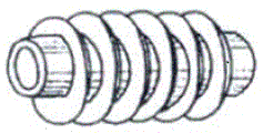
In the coal steam drying rotary furnace, the inner and outer surfaces of the heating tube array are smooth surfaces, and when a gas medium flows in and out of the heating tube array, a gas boundary layer with a certain thickness is formed on the wall surface due to the relative speed between the gas and the wall surface. The thickness of the boundary layer is related to the fluid velocity, and the thicker the boundary layer, the greater the thermal resistance. The existence of the boundary layer where the gas medium flows on the wall surface reduces the heat transfer quantity of the inner side and the outer side of the heating tube array. FIG. 3 is a structure of a convective heat transfer boundary layer on the tube wall of a tube array.
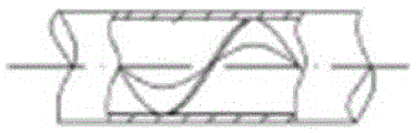
In the coal steam drying rotary furnace, when the heating medium in the steam array pipe is steam, the steam contacts the wall surface below the saturation temperature, and film-shaped solidification is formed on the wall surface. The solidified wall surface is covered by a layer of liquid film, the phase change latent heat released by the condensation can be transferred to the cooling wall surface only through the liquid film, and then the liquid film becomes the main heat resistance of heat exchange. Meanwhile, after a liquid film is generated in the steam array tube in the rotary furnace, when the flow rate of the steam is low, the condensed liquid is accumulated at the bottom in the tube, and the steam is positioned at the upper part in the tube. Along with the proceeding of the heat exchange process, the thickness of the liquid film is continuously thickened, the heat exchange thermal resistance of the inner wall of the pipeline is continuously increased, and the heat transfer quantity from the steam array pipe to the coal is reduced. In addition, the low temperature of the steam causes the low drying temperature of the cylinder wall of the rotary furnace, and is also an important factor influencing the heat transfer quantity in the rotary furnace. FIG. 4 is a schematic diagram of the heat exchange process inside the steam tubes.
SUMMERY OF THE UTILITY MODEL
The utility model aims at providing a coal steam drying rotary furnace of improvement coal drying temperature in the rotary furnace, improvement heat transfer efficiency, reduction steam use amount reinforces heat transfer device to the coal drying temperature that current coal steam drying rotary furnace exists low, coal and burner gas heat exchange efficiency are low, the inboard and outside thermal resistance of shell and tube is big, the interior airflow velocity of rotary furnace is low, rotary furnace section of thick bamboo wall temperature hangs down the scheduling problem.
In order to satisfy the above-mentioned purpose, the utility model discloses the technical scheme who takes does:
a coal steam drying rotary furnace enhanced heat transfer device comprises a coal steam drying rotary furnace, one end of the coal steam drying rotary furnace is a feed inlet, the other end of the coal steam drying rotary furnace is a discharge hole, 2-5 circles of steam tubes penetrating through the whole cylinder are arranged in the coal steam drying rotary furnace in a concentric circle mode along the length direction of the furnace, the steam array pipe is fixed on the inner wall of the coal steam drying rotary furnace through a rib plate, a carrier gas inlet is arranged at the feed port end, the upper end of the discharge port is provided with a carrier gas outlet, a plurality of low-temperature flue gas tubes are arranged in the coal steam drying rotary furnace along the furnace length direction, the low-temperature flue gas array pipes are distributed in a star shape along the circumferential direction of the inner wall of the coal steam drying rotary furnace, the low-temperature flue gas tube is positioned above the coal charge level in the coal steam drying rotary furnace and is not contacted with coal.
Preferably, the coal steam drying rotary furnace is provided with a plurality of lifting plates along the furnace length direction, and one side of each lifting plate is welded on the inner wall of a cylinder of the coal steam drying rotary furnace.
Preferably, fins which are integrated with the wall surface are arranged on the outer surfaces of the steam array pipe and the low-temperature flue gas array pipe of the coal steam drying rotary furnace, and the expansion surface area of each fin is 2-7 times of that of the smooth surface.
Preferably, twist-shaped metal inserts are additionally arranged inside the steam tube array and the low-temperature flue gas tube array of the coal steam drying rotary furnace.
Preferably, the carrier gas of the coal steam drying rotary furnace adopts low-temperature flue gas at the temperature of 300-350 ℃ discharged from a gas retort, and the low-temperature flue gas and coal adopt a concurrent heat exchange mode.
Preferably, the steam array pipe and the low-temperature flue gas array pipe of the coal steam drying rotary furnace adopt low-temperature flue gas at the temperature of 300-350 ℃ discharged by a gas retort, and the low-temperature flue gas and coal adopt a countercurrent heat exchange mode.
Preferably, a jacket cylinder is arranged on the inner side of the cylinder wall of the coal steam drying rotary furnace, a jacket is formed between the jacket cylinder and the inner wall of the coal steam drying rotary furnace, low-temperature flue gas at the temperature of 300-350 ℃ discharged from the carbonization furnace is introduced into the annular jacket, and heat is transferred into the rotary furnace through the waste heat of the low-temperature flue gas in the jacket.
Preferably, a furnace gas circulating fan is arranged outside the coal steam drying rotary furnace, and the furnace gas circulating fan pressurizes a part of furnace gas discharged from a carrier gas outlet of the coal steam drying rotary furnace through the circulating fan and then blows the furnace gas from a feeding end of the coal steam drying rotary furnace.
The utility model has the advantages that:
(1) in the coal steam drying rotary furnace, low-temperature flue gas discharged by the coal carbonization furnace is used as a heat source, and the drying temperature of the coal can be increased to 270-300 ℃ by adopting a mode of indirect or direct heat exchange between the flue gas and the coal;
(2) in the coal steam drying rotary furnace, the material raising plates are arranged on the cylinder wall of the inner side of the furnace body, the insertion pieces are arranged on the inner sides of the tubes, the fins are arranged on the outer sides of the tubes, and the jacket is arranged on the inner side of the cylinder wall of the furnace body, so that the heat transfer efficiency of coal can be enhanced, and the coal drying quality can be improved;
(3) in the coal steam drying rotary furnace, low-temperature flue gas discharged by the coal carbonization furnace is used as carrier gas, low-temperature flue gas at the temperature of 300-350 ℃ discharged by the carbonization furnace is also used in each row pipe, and a furnace gas circulating device is arranged, so that heat transfer in the coal steam drying rotary furnace is enhanced, the purpose of improving the drying capacity of coal is achieved, the recycling of energy is improved, and the effects of environmental protection and energy conservation are achieved.
Drawings
FIG. 1 is a view showing the conventional structure of a rotary kiln for drying coal;
FIG. 2 is a prior art furnace gas stratification profile in a rotary furnace;
FIG. 3 is a prior art shell and tube wall convective heat transfer boundary layer structure;
FIG. 4 is a schematic view of the interior of a prior art steam tube array;
FIG. 5 is a schematic structural view of the present invention;
FIG. 6 is a schematic structural view of a jacket cylinder diagram and a material raising plate additionally arranged in the rotary furnace;
FIG. 7 is a schematic view of the arrangement of the outer wall of each tube array with fins and the inner wall with inserts;
FIG. 8 is an isometric view of the outer wall of each tube array provided with ribs;
FIG. 9 is a cross-sectional view of the interior of each of the tubes with an insert disposed therein;
in the figure: 1. the coal steam drying rotary furnace comprises a coal steam drying rotary furnace, a feed inlet, a discharge outlet, a steam array pipe, a low-temperature flue gas array pipe, a lifting blade, a jacket cylinder, a jacket, fins, a metal insert, a carrier gas inlet, a carrier gas outlet and a cooling device, wherein the coal steam drying rotary furnace comprises 2 feed inlets, 3 discharge outlets, 4 steam array pipes, 5 low-temperature flue gas array pipes, 6 lifting blades, 7 jacket cylinders, 8 jackets, 9.
Detailed Description
The present invention will be further explained with reference to the accompanying drawings and the working principle:
in a coal steam drying rotary furnace, when a heating tube array is positioned in a coal bed in the rotary furnace, the heat transfer process between the tube wall and coal comprises the following steps: firstly, heat is transferred to the inner wall of a heating pipe by steam in the pipe through a heat transfer mode of condensation or convection; secondly, the inner wall of the heating tube transfers the received heat to the outer wall of the heating tube in a heat conduction mode; thirdly, the outer wall of the heating pipe transfers heat to particles and gas in the material layer close to the wall surface from the outer wall of the heating pipe in the modes of conduction heat transfer and radiation heat transfer; fourthly, the particles close to the wall surface material layer transfer heat to the particles far away from the wall surface in the material layer through radiation heat transfer, conduction heat transfer and other modes; fifthly, the particles transfer heat from the surface to the interior of the particles through conduction and heat transfer.
In the coal steam drying rotary furnace, when the heating tube array is positioned above the coal seam, the heat transfer process comprises the following steps: firstly, steam in the tubes transfers the heat of the steam to the inner wall of the heating tube in a heat transfer mode of condensation or convection; secondly, the inner wall of the heating tube transfers the received heat to the outer wall of the heating tube in a heat conduction mode; thirdly, the outer wall of the heating pipe transfers heat to furnace gas, the furnace wall which is not contacted with coal and the coal on the surface of the material layer in the form of conduction heat transfer and radiation heat transfer; the furnace wall which is not contacted with the coal transfers the received heat to the coal on the surface of the material layer in the forms of convection and radiation; fifthly, the coal on the surface of the coal transfers heat from the surface to the interior of the coal through conduction heat transfer and radiation heat transfer.
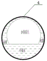
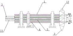
A coal steam drying rotary furnace enhanced heat transfer device comprises a coal steam drying rotary furnace 1, wherein one end of the coal steam drying rotary furnace 1 is a feed inlet 2, the other end of the coal steam drying rotary furnace 1 is a discharge outlet 3, 2-5 circles of steam array pipes 4 penetrating through the whole cylinder are arranged in the coal steam drying rotary furnace 1 in a concentric circle mode along the furnace length direction, the steam array pipes 4 are fixed on the inner wall of the coal steam drying rotary furnace 1 through rib plates, a carrier gas inlet 11 is arranged at the end of the feed inlet 2, a carrier gas outlet 12 is arranged at the upper end of the discharge outlet 3, a plurality of low-temperature flue gas array pipes 5 are arranged in the coal steam drying rotary furnace 1 along the furnace length direction, the low-temperature flue gas array pipes 5 are distributed in a star shape along the circumferential direction of the inner wall of the coal steam drying rotary furnace 1, the low-temperature flue gas array pipes 5 are positioned above the coal charge level in the coal steam, on the basis of an original steam tube array 4 of a coal steam drying rotary furnace 1, a plurality of low-temperature flue gas tube arrays 5 are additionally arranged along the furnace length direction, the low-temperature flue gas tube arrays 5 are distributed in a star shape along the circumferential direction of the rotary furnace, low-temperature flue gas at 300-350 ℃ discharged by the coal gas retort is introduced into the tube arrays, the heat of the flue gas is used as a supplementary heat source of the coal steam drying rotary furnace 1, the additionally arranged low-temperature flue gas tube arrays 5 are positioned above the coal charge level and are not in contact with coal, the low-temperature flue gas in the tubes transfers heat to the inner walls of the tubes in a convection and radiation heat transfer mode, transfers heat through conduction of the tube walls of the tubes and then transfers heat to the outer walls of the tubes, and finally transfers heat to furnace gas, the furnace wall which is not in contact with coal and the coal on the surface of the material layer in a convection and radiation heat transfer mode, the temperature of coal discharged from the rotary furnace can be increased to 220-250 ℃ while the output of a single furnace of the rotary furnace is increased. FIG. 5 is a diagram of the rotary furnace with low-temperature flue gas tubes.
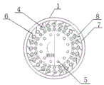
Coal steam drying rotary furnace 1 is provided with a plurality of lifting blade 6 along the furnace length direction, and one side welding of lifting blade 6 is on coal steam drying rotary furnace 1's drum inner wall, on the basis of coal steam drying rotary furnace 1 original structure, sets up a plurality of lifting blades 6 along the furnace length direction, and one side welding of lifting blade 6 is on the drum inner wall, and its effect is as follows: 1) the lifting plate can lift coal at the bottom of the rotary furnace and throw the coal from the top of the cylinder, and the thrown coal generates relative motion with high-temperature gas in the rotary furnace in the falling process, so that the convection and radiation heat exchange quantity of the coal and furnace gas can be increased; 2) the lifting plate is welded on the inner side of the wall of the furnace body, so that the contact area between the coal and the lifting plate is increased, and the heat transfer quantity from the inner wall of the cylinder to the coal is increased; 3) in the rotary furnace, the lifting plate lifts part of coal in the rotating process, so that the thickness of a material layer of crescent coal at the bottom of the cylinder is reduced, and moisture in the coal in the material layer is easily discharged from the inside of the coal. FIG. 6 shows a material lifting plate structure arranged in the rotary kiln.
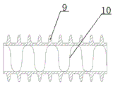
The external surfaces of a steam tube array 4 and a low-temperature flue gas tube array 5 of the coal steam drying rotary furnace 1 are provided with fins 9 which are integrated with the wall surface, the expansion surface area of the fins 9 is 2-7 times of that of the smooth surface, in the coal steam drying rotary furnace 1, the gas medium at the outer sides of the tube arrays is mainly diatomic gas such as N2, H2, CO and the like, namely, radiation force is not generated, and radiation is not absorbed, so only convection heat transfer is realized, but when the coal is dried, water enters the gas medium, and certain radiation heat transfer can be generated because the water steam belongs to the triatomic gas. Therefore, the heat transfer enhancement of the outer side of the tube array in the rotary furnace mainly reduces the boundary layer thermal resistance of gas flow, and the thickness of the boundary layer close to the tube wall can be reduced by adopting a method for improving the gas flow speed in the furnace, so that the heat transfer thermal resistance is reduced, and the convection heat transfer quantity is improved; based on the above principle, the utility model discloses an add on the tubulation surface and from integrative fin 9 with the wall, the extension surface area of fin 9 is 2-7 times of smooth surface, can show the radiating extension surface of improvement tubulation. The tube array with the fins 9 can increase the heat transfer area and increase the airflow disturbance, thereby improving the heat transfer quantity of the outer surface of the tube array. Fig. 7 is a diagram of ribs arranged on the outer wall of the tube array, and fig. 8 is a structural diagram of heat conducting ribs arranged on the outer wall of the tube array.
The twisted metal inserts 10 are additionally arranged inside the steam tube array 4 and the low-temperature flue gas tube array 5 of the rotary coal steam drying furnace 1, in the rotary coal steam drying furnace 1, the heat exchange efficiency inside the tube array is directly related to the overall heat exchange performance of the rotary coal steam drying furnace 1, meanwhile, the tube array can generate scale after long-time operation, the scale is deposited on the surface of a heat exchange tube, the flow resistance of fluid can be increased, and the heat transfer efficiency of the tube array is reduced. Inserting in the tubulation a twisted metal insert 10 which has the function of: increasing the flow speed and the stroke of airflow to generate continuous rotating vortex in the pipe, thereby thinning or destroying the boundary layer of the inner wall surface of the pipe; secondly, the heat exchange area in the tube is increased, the heat transfer in the tube is strengthened, and the dirt in the tube is removed; based on the principle, the twisted metal insert 10 is additionally arranged in the tube nest of the coal steam drying rotary furnace 1, so that the heat transfer quantity of steam to the inner wall of the tube nest can be improved. Fig. 7 is a view showing an insert provided on the inner wall of the tube array, and fig. 9 is a view showing a structure of an insert provided inside the tube array.
The carrier gas of the coal steam drying rotary furnace 1 adopts low-temperature flue gas with the temperature of 300-.
The low-temperature flue gas with the temperature of 300-350 ℃ discharged from the gas retort is adopted in the steam tube array 4 and the low-temperature flue gas tube array 5 of the coal steam drying rotary furnace 1, the low-temperature flue gas and the coal adopt a countercurrent heat exchange mode, the waste heat of the flue gas discharged from the gas retort can be recycled, the drying temperature of the coal of the rotary furnace can be greatly improved under the condition of not using steam, and the method is a recycling method of resources, is environment-friendly and saves energy.
The inner side of the cylinder wall of the coal steam drying rotary furnace 1 is provided with a jacket cylinder 7, a jacket 8 is formed between the jacket cylinder 7 and the inner wall of the coal steam drying rotary furnace 1, low-temperature flue gas with the temperature of 300-350 ℃ discharged by the carbonization furnace is introduced into the annular jacket 8, heat is transferred into the rotary furnace through the waste heat of the low-temperature flue gas in the jacket 8, the temperature of the inner wall of the coal steam drying rotary furnace 1 is heated through the low-temperature flue gas in the jacket 8, and the drying temperature of coal in the coal steam drying rotary furnace 1 can be improved.
A furnace gas circulating fan is arranged outside the coal steam drying rotary furnace 1, a part of furnace gas discharged from a carrier gas outlet 12 of the coal steam drying rotary furnace 1 is pressurized by the circulating fan and then is blown in from a feeding end 2 of the coal steam drying rotary furnace 1, and circulating gas in the coal steam drying rotary furnace 1 is introduced, so that the gas velocity in the furnace can be improved, the convection heat transfer quantity of coal is improved, meanwhile, the gas circulation can be used for uniformly distributing gas flow in the furnace, and the existence of a low-temperature gas layer in the furnace is prevented.
Claims (8)
1. The utility model provides a coal steam drying rotary furnace reinforces heat transfer unit, includes coal steam drying rotary furnace, the one end of coal steam drying rotary furnace is the feed inlet, the other end of coal steam drying rotary furnace is the discharge gate, arrange 2-5 rings of steam that run through in whole barrel along the stove length direction in the coal steam drying rotary furnace with concentric circles mode and be listed as the pipe, the steam is listed as the pipe and is fixed on the stove inner wall of coal steam drying rotary furnace through the gusset, the feed inlet end is provided with the carrier gas entry, the upper end of discharge gate is provided with the carrier gas export, its characterized in that: the coal steam drying rotary furnace is characterized in that a plurality of low-temperature flue gas array pipes (5) are arranged in the coal steam drying rotary furnace (1) along the furnace length direction, the low-temperature flue gas array pipes (5) are distributed in a star shape along the circumferential direction of the inner wall of the coal steam drying rotary furnace (1), and the low-temperature flue gas array pipes (5) are located above the coal charge level in the coal steam drying rotary furnace (1) and do not contact with coal.
2. The coal steam drying rotary furnace enhanced heat transfer device of claim 1, which is characterized in that: the coal steam drying rotary furnace (1) is provided with a plurality of lifting plates (6) along the length direction of the furnace, and one side of each lifting plate (6) is welded on the inner wall of a cylinder of the coal steam drying rotary furnace (1).
3. The coal steam drying rotary furnace enhanced heat transfer device of claim 1, which is characterized in that: fins (9) which are integrated with the wall surface are arranged on the outer surfaces of the steam array pipe (4) and the low-temperature flue gas array pipe (5) of the coal steam drying rotary furnace (1), and the expansion surface area of each fin (9) is 2-7 times of that of the smooth surface.
4. The coal steam drying rotary furnace enhanced heat transfer device of claim 1, which is characterized in that: twisted metal inserts (10) are additionally arranged inside the steam tube nest (4) and the low-temperature flue gas tube nest (5) of the coal steam drying rotary furnace (1).
5. The coal steam drying rotary furnace enhanced heat transfer device of claim 1, which is characterized in that: the carrier gas of the coal steam drying rotary furnace (1) adopts low-temperature flue gas at the temperature of 300-350 ℃ discharged from a gas retort, and the low-temperature flue gas and coal adopt a concurrent heat exchange mode.
6. The coal steam drying rotary furnace enhanced heat transfer device of claim 1 or 4, characterized in that: low-temperature flue gas at the temperature of 300-350 ℃ discharged from a carbonization furnace is adopted in a steam tube array (4) and a low-temperature flue gas tube array (5) of the coal steam drying rotary furnace (1), and the low-temperature flue gas and coal adopt a countercurrent heat exchange mode.
7. The coal steam drying rotary furnace enhanced heat transfer device of claim 1, which is characterized in that: the inner side of the cylinder wall of the coal steam drying rotary furnace (1) is provided with a jacket cylinder (7), a jacket (8) is formed between the jacket cylinder (7) and the inner wall of the coal steam drying rotary furnace (1), 300-350 ℃ low-temperature flue gas discharged from the carbonization furnace is introduced into the annular jacket (8), and heat is transferred into the rotary furnace through the waste heat of the low-temperature flue gas in the jacket (8).
8. The coal steam drying rotary furnace enhanced heat transfer device of claim 1, which is characterized in that: a furnace gas circulating fan is arranged outside the coal steam drying rotary furnace (1), and the furnace gas circulating fan pressurizes a part of furnace gas discharged from a carrier gas outlet (12) of the coal steam drying rotary furnace (1) through the circulating fan and then blows the furnace gas from a feeding end (2) of the coal steam drying rotary furnace (1).
Priority Applications (1)
| Application Number | Priority Date | Filing Date | Title |
|---|---|---|---|
| CN201921755749.1U CN211854707U (en) | 2019-10-18 | 2019-10-18 | Enhanced heat transfer device of coal steam drying rotary furnace |
Applications Claiming Priority (1)
| Application Number | Priority Date | Filing Date | Title |
|---|---|---|---|
| CN201921755749.1U CN211854707U (en) | 2019-10-18 | 2019-10-18 | Enhanced heat transfer device of coal steam drying rotary furnace |
Publications (1)
| Publication Number | Publication Date |
|---|---|
| CN211854707U true CN211854707U (en) | 2020-11-03 |
Family
ID=73131356
Family Applications (1)
| Application Number | Title | Priority Date | Filing Date |
|---|---|---|---|
| CN201921755749.1U Expired - Fee Related CN211854707U (en) | 2019-10-18 | 2019-10-18 | Enhanced heat transfer device of coal steam drying rotary furnace |
Country Status (1)
| Country | Link |
|---|---|
| CN (1) | CN211854707U (en) |
Cited By (1)
| Publication number | Priority date | Publication date | Assignee | Title |
|---|---|---|---|---|
| CN113731044A (en) * | 2021-09-27 | 2021-12-03 | 联峰钢铁(张家港)有限公司 | Energy-concerving and environment-protective steel smelting processingequipment |
-
2019
- 2019-10-18 CN CN201921755749.1U patent/CN211854707U/en not_active Expired - Fee Related
Cited By (1)
| Publication number | Priority date | Publication date | Assignee | Title |
|---|---|---|---|---|
| CN113731044A (en) * | 2021-09-27 | 2021-12-03 | 联峰钢铁(张家港)有限公司 | Energy-concerving and environment-protective steel smelting processingequipment |
Similar Documents
| Publication | Publication Date | Title |
|---|---|---|
| CN203629241U (en) | Vacuum drying tower | |
| CN201028471Y (en) | Low-temperature waste-gas exhaust-heat boiler of sintering cooler | |
| CN211854707U (en) | Enhanced heat transfer device of coal steam drying rotary furnace | |
| CN104789761B (en) | A kind of reduced iron efficiently cooling and waste-heat recovery device | |
| CN206563501U (en) | A kind of rotary kiln cement clinker production line waste heat recycling system | |
| CN206352947U (en) | A kind of Split high-efficiency heat pump dryer | |
| CN202442318U (en) | Vacuum tube heat exchanger | |
| CN206262122U (en) | Integrated MVR evaporation dryings system | |
| CN104764312B (en) | Vacuum drying tower | |
| CN207699946U (en) | The hot drying cylinder heat recovery system of magnetic | |
| CN112212681A (en) | Enhanced heat transfer device and method for coal steam drying rotary furnace | |
| CN206073756U (en) | A kind of staged exchanges heat compound closed cooling tower | |
| CN214148783U (en) | Enhanced heat transfer device of coal steam drying rotary furnace | |
| CN106802090A (en) | A kind of rotary kiln cement clinker production line waste heat recycling system | |
| CN204388525U (en) | Hot blast vacuum economic benefits and social benefits drying tower | |
| CN205679076U (en) | A kind of combined type little particle semicoke cooling and waste-heat recovery device | |
| CN205156588U (en) | Dry storehouse of heat pipe that can waste heat utilization | |
| CN112129089A (en) | Hierarchical formula living beings cylinder drying-machine | |
| CN109825705B (en) | Device and method for recycling mercury from waste mercury catalyst | |
| CN213578627U (en) | Hierarchical formula living beings cylinder drying-machine | |
| CN202993141U (en) | Distributed waste heat boiler based on carbon plant calcining furnace calcined coke attached heat pipe heat exchange | |
| CN105910448B (en) | A kind of combined type little particle semicoke cooling and waste-heat recovery device | |
| CN213823494U (en) | Energy-concerving and environment-protective steam preheating tank | |
| CN206094928U (en) | Calcium carbide furnace tail gas recovery device | |
| CN218025930U (en) | Dry quenching system |
Legal Events
| Date | Code | Title | Description |
|---|---|---|---|
| GR01 | Patent grant | ||
| GR01 | Patent grant | ||
| CF01 | Termination of patent right due to non-payment of annual fee |
Granted publication date: 20201103 Termination date: 20211018 |
|
| CF01 | Termination of patent right due to non-payment of annual fee |