CN211841506U - Machining grinder - Google Patents
Machining grinder Download PDFInfo
- Publication number
- CN211841506U CN211841506U CN202020336838.9U CN202020336838U CN211841506U CN 211841506 U CN211841506 U CN 211841506U CN 202020336838 U CN202020336838 U CN 202020336838U CN 211841506 U CN211841506 U CN 211841506U
- Authority
- CN
- China
- Prior art keywords
- block
- fixed
- fixedly connected
- workbench
- collecting box
- Prior art date
- Legal status (The legal status is an assumption and is not a legal conclusion. Google has not performed a legal analysis and makes no representation as to the accuracy of the status listed.)
- Expired - Fee Related
Links
Images

Landscapes
- Finish Polishing, Edge Sharpening, And Grinding By Specific Grinding Devices (AREA)
Abstract
The utility model discloses a machining grinding device, which belongs to the technical field of grinding and comprises a workbench, wherein a fixed block and two fixed plates are arranged above the workbench, the fixed block is positioned between the two fixed plates, a screw rod is connected on the fixed block in a screwing way, one side of the screw rod is fixedly welded with a connecting block, a mounting groove is arranged on the connecting block, a rubber block is arranged inside the mounting groove, a connecting plate is fixedly connected between the two fixed plates, one side of one fixed plate is fixedly connected with an electric telescopic rod through a bolt, the bottom of the connecting plate is connected with a slide block in a sliding way, the slide block is fixedly connected with the electric telescopic rod through a bolt, the groove plays the role of placing a collecting box by arranging the groove and the collecting box, and the collecting box can collect dust particles falling during mechanical grinding, prevent that the dust granule from dropping on the workstation, the operating personnel of being not convenient for clears up.
Description
Technical Field
The utility model belongs to the technical field of grind, concretely relates to machining grinder.
Background
Grinding utilizes abrasive particles coated or pressed on a grinding tool to perform finishing processing (such as cutting processing) on a processing surface through relative movement of the grinding tool and a workpiece under a certain pressure. The grinding can be used for processing various metal and non-metal materials, and the processed surface has the shapes of planes, inner and outer cylindrical surfaces, conical surfaces, convex and concave spherical surfaces, threads, tooth surfaces and other molded surfaces. The processing precision can reach IT 5-01, the surface roughness can reach Ra0.63-0.01 micron, the grinding tool is a tool for grinding and forming a workpiece, and simultaneously is a carrier of an abrasive, the hardness of the grinding tool is lower than that of the workpiece, the grinding tool has certain wear resistance, and the grinding tool is made of common gray cast iron. The wet grinding tool has a metallographic structure mainly comprising ferrite, and the dry grinding tool has a homogeneous and fine pearlite as a matrix. For grinding small workpieces with complicated shapes and threads below M5, mild steel grinding tools are commonly used. Brass and red copper grinding tools are mostly used for grinding small holes and soft metal materials. The lapping tool should have sufficient rigidity and a working surface with high geometric accuracy. The grinding tool is also subjected to cutting and abrasion in the grinding process, and if the grinding tool is properly operated, the precision of the grinding tool can be improved, so that the machining precision of a workpiece can be higher than the original precision of the grinding tool.
The existing mechanical processing grinding device is not convenient enough to clean dust generated during grinding, the cleaning difficulty of operators is increased, and the grinding device easily causes damage to the surface of a machine when the machine is fixed, so that the attractiveness of the machine is affected.
SUMMERY OF THE UTILITY MODEL
An object of the utility model is to provide a machining grinder to solve the problem of proposing among the above-mentioned background art.
In order to achieve the above object, the utility model provides a following technical scheme: a machining grinding device comprises a workbench, wherein a fixed block and two fixed plates are arranged above the workbench, the fixed block is positioned between the two fixed plates, a screw is screwed on the fixed block, a connecting block is welded and fixed on one side of the screw, a mounting groove is formed in the connecting block, a rubber block is arranged in the mounting groove, a connecting plate is fixedly connected between the two fixed plates, an electric telescopic rod is fixedly connected on one side of one of the fixed plates through a bolt, a sliding block is slidably connected at the bottom of the connecting plate, the sliding block and the electric telescopic rod are fixedly connected through a bolt, an electric push rod is fixedly connected below the sliding block through a bolt, a motor is arranged below the electric push rod, a grinding head is rotatably connected below the motor through a rotating shaft, a groove is formed in the top end of the workbench, the inside of recess is provided with the collecting box, the preceding table wall of workstation is provided with the power strip, electric putter, electric telescopic handle and motor all with power strip electric connection.
By adopting the scheme, the groove plays a role in placing the collecting box, the collecting box can collect dust particles falling off when mechanical grinding, the dust particles are prevented from falling on the workbench, an operator is not convenient to clean, the mounting groove plays a role in installing the rubber block, the rubber block can prevent the connecting block from being attached to the machine, the machine outer surface wall is easily scratched when the machine two sides are fixed, and the attractiveness of the machine is influenced.
As a preferred embodiment, the top end of the collecting box is provided with clamping plates on two sides.
Adopt above-mentioned scheme, the cardboard prevents that the collecting box from dropping in the inside of recess, and the operating personnel of being not convenient for takes out.
As a preferred embodiment, the bottom of the connecting plate is provided with a sliding groove matched with the sliding block.
By adopting the scheme, the sliding of the sliding block is convenient, the sliding block can slide to adjust the position of the grinding head, and the grinding at different positions is carried out on the machine.
In a preferred embodiment, a support column is fixedly connected below the workbench through a bolt.
By adopting the scheme, the supporting column plays a role in supporting the workbench, so that the workbench can stand on the ground more stably.
In a preferred embodiment, the outer surface wall of the rubber block is provided with anti-slip lines.
Adopt above-mentioned scheme, prevent that the block rubber from laminating when machinery both sides, machinery slips easily from the block rubber, unable fixed machinery.
Compared with the prior art, the beneficial effects of the utility model are that:
this machining grinder is through setting up recess and collecting box, and the recess plays the effect of placing the collecting box, and the dust granule that drops when the collecting box can collect mechanical grinding prevents that the dust granule from dropping on the workstation, and the operating personnel of being not convenient for clears up.
This machining grinder is through setting up block rubber and mounting groove, and the mounting groove plays the effect of installation block rubber, and the block rubber can prevent that the connecting block laminating from fixing machinery in machinery both sides, easily with mechanical exterior wall fish tail, influence mechanical pleasing to the eye.
Drawings
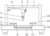
Fig. 1 is a schematic view of the internal structure of the present invention;
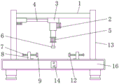
FIG. 2 is an external view of the present invention;
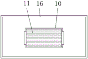
fig. 3 is a top view of the working table of the present invention;
fig. 4 is a side view of the connection block of the present invention.
In the figure: 1. a connecting plate; 2. an electric push rod; 3. a slider; 4. an electric telescopic rod; 5. a motor; 6. a grinding head; 7. a screw; 8. a fixed block; 9. a rubber block; 10. a groove; 11. a collection box; 12. connecting blocks; 13. a fixing plate; 14. a power panel; 15. mounting grooves; 16. a work bench.
Detailed Description
The present invention will be further described with reference to the following examples.
The following examples are intended to illustrate the invention, but are not intended to limit the scope of the invention. The condition in the embodiment can be further adjusted according to concrete condition the utility model discloses a it is right under the design prerequisite the utility model discloses a simple improvement of method all belongs to the utility model discloses the scope of claiming.
The utility model provides a machining grinding device, please refer to fig. 1-4, which comprises a workbench 16, a fixed block 8 and two fixed plates 13 are arranged above the workbench 16, the fixed block 8 is positioned between the two fixed plates 13, a screw 7 is connected on the fixed block 8 in a rotating manner, a connecting block 12 is fixed on one side of the screw 7 in a welding manner, a mounting groove 15 is arranged on the connecting block 12, a rubber block 9 is arranged in the mounting groove 15, a connecting plate 1 is fixedly connected between the two fixed plates 13, one side of one of the fixed plates 13 is fixedly connected with an electric telescopic rod 4 through a bolt, a sliding block 3 is connected at the bottom of the connecting plate 1 in a sliding manner, the sliding block 3 is fixedly connected with the electric telescopic rod 4 through a bolt, an electric push rod 2 is fixedly connected below the sliding block 3 through a bolt, a motor 5 is arranged below the electric push rod 2, a, the top of workstation 16 is seted up flutedly 10, and the inside of recess 10 is provided with collecting box 11, and the preceding table wall of workstation 16 is provided with power strip 14, and electric putter 2, electric telescopic handle 4 and motor 5 all are with power strip 14 electric connection.
Clamping plates are arranged on two sides of the top end of the collecting box 11 (see figures 1, 2 and 3); the catch plate prevents the collecting bin 11 from falling inside the recess 10, not being accessible for the operator.
The bottom of the connecting plate 1 is provided with a sliding chute (not shown) matched with the sliding block 3; the sliding of the sliding block 3 is convenient, the sliding block 3 can adjust the position of the grinding head 6, and the machine is ground at different positions.
A support column is fixedly connected below the workbench 16 through a bolt (see fig. 1 and 2); the support columns serve to support the work table 16, facilitating the work table 16 to stand on the ground more stably.
The outer surface wall of the rubber block 9 is provided with anti-skid grains (not shown); when the rubber block 9 is attached to two sides of the machine, the machine is easy to slip off the rubber block 9, and the machine cannot be fixed.
When the grinding tool is used, an operator firstly rotates the two screw rods 7, a machine to be ground is fixed between the two connecting blocks 12, then the electric telescopic rod 4 is started through the power panel 14, the electric telescopic rod 4 can drive the sliding block 3 to stretch, the position of the grinding head 6 is adjusted, then the electric push rod 2 is started through the power panel 14, the electric push rod 2 drives the motor 5 to move downwards, the motor 5 drives the grinding head 6 to rotate through a rotating shaft, the machine is ground, the groove 10 plays a role in placing the collecting box 11, the collecting box 11 can collect dust particles falling off during mechanical grinding, the dust particles are prevented from falling on the workbench 16 and are not convenient for the operator to clean, the mounting groove 15 plays a role in mounting the rubber block 9, the rubber block 9 can prevent the connecting blocks 12 from being attached to two sides of the machine to fix the machine, and the outer wall of the machine is easily scratched, affecting the aesthetic appearance of the machine.
Although embodiments of the present invention have been shown and described, it will be appreciated by those skilled in the art that changes, modifications, substitutions and alterations can be made in these embodiments without departing from the principles and spirit of the invention, the scope of which is defined in the appended claims and their equivalents.
Claims (5)
1. A machining grinding device, includes workstation (16), its characterized in that: the upper part of the workbench (16) is provided with a fixed block (8) and two fixed plates (13), the fixed block (8) is positioned between the two fixed plates (13), the fixed block (8) is connected with a screw rod (7) in a rotating and combining manner, one side of the screw rod (7) is fixedly welded with a connecting block (12), the connecting block (12) is provided with a mounting groove (15), the inside of the mounting groove (15) is provided with a rubber block (9), a connecting plate (1) is fixedly connected between the two fixed plates (13), one side of one fixed plate (13) is fixedly connected with an electric telescopic rod (4) through a bolt, the bottom of the connecting plate (1) is slidably connected with a sliding block (3), the sliding block (3) is fixedly connected with the electric telescopic rod (4) through a bolt, the lower part of the sliding block (3) is fixedly connected with an electric, the grinding head is characterized in that a motor (5) is arranged below the electric push rod (2), a grinding head (6) is rotatably connected below the motor (5) through a rotating shaft, a groove (10) is formed in the top end of the workbench (16), a collecting box (11) is arranged inside the groove (10), a power panel (14) is arranged on the front surface wall of the workbench (16), and the electric push rod (2), the electric telescopic rod (4) and the motor (5) are all electrically connected with the power panel (14).
2. A machining grinding apparatus as claimed in claim 1, wherein: clamping plates are arranged on two sides of the top end of the collecting box (11).
3. A machining grinding apparatus as claimed in claim 1, wherein: the bottom of the connecting plate (1) is provided with a sliding groove matched with the sliding block (3).
4. A machining grinding apparatus as claimed in claim 1, wherein: and a support column is fixedly connected below the workbench (16) through a bolt.
5. A machining grinding apparatus as claimed in claim 1, wherein: the outer surface wall of the rubber block (9) is provided with anti-skid grains.
Priority Applications (1)
| Application Number | Priority Date | Filing Date | Title |
|---|---|---|---|
| CN202020336838.9U CN211841506U (en) | 2020-03-18 | 2020-03-18 | Machining grinder |
Applications Claiming Priority (1)
| Application Number | Priority Date | Filing Date | Title |
|---|---|---|---|
| CN202020336838.9U CN211841506U (en) | 2020-03-18 | 2020-03-18 | Machining grinder |
Publications (1)
| Publication Number | Publication Date |
|---|---|
| CN211841506U true CN211841506U (en) | 2020-11-03 |
Family
ID=73135236
Family Applications (1)
| Application Number | Title | Priority Date | Filing Date |
|---|---|---|---|
| CN202020336838.9U Expired - Fee Related CN211841506U (en) | 2020-03-18 | 2020-03-18 | Machining grinder |
Country Status (1)
| Country | Link |
|---|---|
| CN (1) | CN211841506U (en) |
Cited By (1)
| Publication number | Priority date | Publication date | Assignee | Title |
|---|---|---|---|---|
| CN112873037A (en) * | 2021-01-08 | 2021-06-01 | 朱巧珍 | Machining grinder |
-
2020
- 2020-03-18 CN CN202020336838.9U patent/CN211841506U/en not_active Expired - Fee Related
Cited By (1)
| Publication number | Priority date | Publication date | Assignee | Title |
|---|---|---|---|---|
| CN112873037A (en) * | 2021-01-08 | 2021-06-01 | 朱巧珍 | Machining grinder |
Similar Documents
| Publication | Publication Date | Title |
|---|---|---|
| CN213470564U (en) | Double-ended grinding machine | |
| CN201693436U (en) | Gantry milling and grinding machine | |
| CN110315422B (en) | Automatic hardware polishing machine and use method thereof | |
| CN211841506U (en) | Machining grinder | |
| CN209754814U (en) | Grinding machine for finish machining of die | |
| CN206475020U (en) | A kind of multistation burnishing device | |
| CN206382994U (en) | A kind of automatic sander polished for USB interface metal shell | |
| CN113245920B (en) | Automatically controlled grinding robot for shaft or column and control method thereof | |
| CN212170063U (en) | Workpiece polishing clamp adaptable to workpieces of different sizes | |
| CN212471051U (en) | Pipe fitting polishing equipment | |
| CN209936682U (en) | Grinding machine with clamping device | |
| CN112264909A (en) | Polishing device and polishing process for metal processing part | |
| CN114393498B (en) | Outer surface polishing machine tool for arc-shaped piece | |
| CN220178969U (en) | Hardware polishing device | |
| CN209394457U (en) | A kind of metal product processing grinding attachment | |
| CN220533788U (en) | Grinding and polishing equipment | |
| CN220548060U (en) | Hard alloy grinding machine | |
| CN219504401U (en) | Grinding machine for machining center | |
| CN216097966U (en) | Deburring device for machining | |
| CN219819266U (en) | Part surface polishing equipment | |
| CN220094161U (en) | Environment-friendly grinding machine | |
| CN114833686B (en) | Multi-station sliding block grinding machine with levelness measuring and early warning mechanism | |
| CN209850621U (en) | Grinding and polishing device | |
| CN216504169U (en) | Industrial design grinding device | |
| CN220637324U (en) | Forming grinder with high processing yield |
Legal Events
| Date | Code | Title | Description |
|---|---|---|---|
| GR01 | Patent grant | ||
| GR01 | Patent grant | ||
| CF01 | Termination of patent right due to non-payment of annual fee |
Granted publication date: 20201103 |
|
| CF01 | Termination of patent right due to non-payment of annual fee |