CN211840741U - Quick assembly jig for automobile seat - Google Patents
Quick assembly jig for automobile seat Download PDFInfo
- Publication number
- CN211840741U CN211840741U CN201922474625.2U CN201922474625U CN211840741U CN 211840741 U CN211840741 U CN 211840741U CN 201922474625 U CN201922474625 U CN 201922474625U CN 211840741 U CN211840741 U CN 211840741U
- Authority
- CN
- China
- Prior art keywords
- slide
- mounting panel
- base
- car seat
- quick
- Prior art date
- Legal status (The legal status is an assumption and is not a legal conclusion. Google has not performed a legal analysis and makes no representation as to the accuracy of the status listed.)
- Active
Links
Images

Abstract
The utility model discloses a car seat fast assembly tool, the on-line screen storage device comprises a base, base upper end fixed mounting has the support column of perpendicular setting, equal slidable mounting in support column both sides has right slide and left slide, right slide and left slide are the relative displacement motion through right cylinder and left cylinder of fixed mounting in the base upper end respectively, right slide and left slide top end department fixedly connected with right mounting panel and left mounting panel respectively. The utility model relates to an equipment tool, in particular to car seat fast assembly tool belongs to car seat processing technology field. The utility model discloses a control cylinder drives and is compressed tightly in back skeleton both sides by the right back mounting panel and the left back mounting panel of centre gripping, and the unblock handle compresses tightly at unblock gangbar end through the quick anchor clamps of handle installation, welds the dress to the relevant position, and the equipment is fast, conveniently welds the dress, has improved production efficiency, and stability is high.
Description
Technical Field
The utility model relates to an equipment tool, in particular to car seat fast assembly tool belongs to car seat processing technology field.
Background
Automobile seat need make up installation and welding to each part in production, and automobile seat skeleton generally includes left and right back mounting panel, back skeleton, unblock gangbar and unblock handle, need fix with fixed tool when installing, but current fixed tool in the use, and it is not high to weld dress efficiency of back skeleton, and stability is not high.
SUMMERY OF THE UTILITY MODEL
An object of the utility model is to provide a car seat fast assembly tool to solve the problem that proposes in the above-mentioned background art.
In order to achieve the above object, the utility model provides a following technical scheme: a quick assembly jig for an automobile seat comprises a base, wherein a vertically arranged support column is fixedly arranged at the upper end of the base, a right sliding plate and a left sliding plate are respectively and slidably arranged at two sides of the support column, the right sliding plate and the left sliding plate are respectively and fixedly arranged on the upper end of the base through a right cylinder and a left cylinder in a relative displacement motion manner, a right mounting plate and a left mounting plate are respectively and fixedly connected with the upper end of the right sliding plate and the left sliding plate, a right quick clamp and a left quick clamp are respectively and fixedly arranged on the inner walls of the right mounting plate and the left mounting plate, the pressing ends of the right quick clamp and the left quick clamp are respectively and vertically arranged with the right mounting plate and the left mounting plate, pressing blocks are respectively and fixedly arranged at the ends of the right sliding plate and the left sliding plate, a handle mounting quick clamp is fixedly arranged at the middle, and the compressing end is fixedly connected with a handle mounting block, and the upper end of the base is fixedly provided with a front quick clamp and a rear quick clamp.
As an optimal technical scheme of the utility model, right side slide and left slide set up slide rail slidable mounting at the base up end through the lower extreme.
As an optimal technical scheme of the utility model, base top both ends difference fixed mounting has preceding quick anchor clamps and back quick anchor clamps.
As a preferred technical scheme of the utility model, base upper end fixed mounting has air valve switch, air valve switch passes through the trachea with right cylinder and left cylinder and is connected.
As a preferred technical scheme of the utility model, two joint pieces of base up end fixedly connected with, two the draw-in groove has all been seted up to the one end that the joint piece is relative.
As a preferred technical scheme of the utility model, the support column is equipped with a plurality ofly, and support column upper end fixedly connected with rubber pad.
Compared with the prior art, the beneficial effects of the utility model are that:
the utility model discloses a control cylinder drives and is compressed tightly in back skeleton both sides by the right back mounting panel and the left back mounting panel of centre gripping, and the unblock handle compresses tightly at unblock gangbar end through the quick anchor clamps of handle installation, welds the dress to the relevant position, and the equipment is fast, conveniently welds the dress, has improved production efficiency, and stability is high.
Drawings
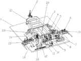
Fig. 1 is a schematic structural view of the present invention;
fig. 2 is a schematic structural diagram of the usage of the present invention.
In the figure: 1. a base; 2. a front quick clamp; 3. a clamping block; 4. a pressing block; 5. a right slide plate; 6. a right cylinder; 7. a right mounting plate; 8. a right quick clamp; 9. a rear quick clamp; 10. an air valve switch; 11. a left quick clamp; 12. a left mounting plate; 13. a handle mounting block; 14. the handle is provided with a quick clamp; 15. a left cylinder; 16. a left slide plate; 17. a support pillar; 18. an unlocking handle; 19. a right back mounting plate; 20. unlocking the linkage rod; 21. a backrest frame; 22. left back mounting plate.
Detailed Description
The technical solutions in the embodiments of the present invention will be described clearly and completely with reference to the accompanying drawings in the embodiments of the present invention, and it is obvious that the described embodiments are only some embodiments of the present invention, not all embodiments. Based on the embodiments in the present invention, all other embodiments obtained by a person skilled in the art without creative work belong to the protection scope of the present invention.
Referring to fig. 1-2, the utility model provides a vehicle seat fast assembly jig, which comprises a base 1, a vertically arranged support column 17 is fixedly arranged at the upper end of the base 1, a right slide plate 5 and a left slide plate 16 are slidably arranged at both sides of the support column 17, the right slide plate 5 and the left slide plate 16 respectively do relative displacement motion through a right cylinder 6 and a left cylinder 15 fixedly arranged at the upper end of the base 1, a right mounting plate 7 and a left mounting plate 12 are respectively fixedly connected at the upper end of the right slide plate 5 and the left slide plate 16, a right fast clamp 8 and a left fast clamp 11 are respectively fixedly arranged at the inner walls of the right mounting plate 7 and the left mounting plate 12, the pressing ends of the right fast clamp 8 and the left fast clamp 11 are respectively vertically arranged with the right mounting plate 7 and the left mounting plate 12, a pressing block 4 is respectively fixedly arranged at the ends of the right slide plate 5, the middle part of the upper end of the left sliding plate 16 is fixedly provided with a handle installation quick clamp 14, the pressing end of the handle installation quick clamp 14 faces the direction of the right sliding plate 5, a pressing end is fixedly connected with a handle installation block 13, and the upper end of the base 1 is fixedly provided with a front quick clamp 2 and a rear quick clamp 9.
The product to be assembled in the utility model is the automobile seat backrest, the automobile seat backrest comprises an unlocking handle 18, a right backrest mounting plate 19, a left backrest mounting plate 22, a backrest framework 21 and an unlocking linkage rod 20, the right backrest mounting plate 19 and the left backrest mounting plate 22 need to be respectively welded at the left side and the right side of the backrest framework 21, the unlocking linkage rod 20 is shaped as a rod body, the unlocking handle 18 is movably arranged at the outer end of the left backrest mounting plate 22 through the shaft holes arranged on the right backrest mounting plate 19 and the unlocking linkage rod 20 and is rotatably inserted between the right backrest mounting plate 19 and the left backrest mounting plate 22, and the unlocking linkage rod 20 is fixedly connected with the unlocking linkage rod 18, the unlocking linkage rod 20 can be driven to rotate when the unlocking handle 18 rotates, the end surfaces of the right backrest mounting plate 19 and the left backrest mounting plate 22 are respectively provided with a positioning hole, and the inner wall of the right mounting plate 7, which is opposite to the left mounting plate 12, is fixedly connected with a positioning inserted rod which is matched with the positioning hole.
The working principle of the present invention will be specifically explained below: when in use, the backrest framework 21 is placed at the upper end of the supporting column 17, the supporting column 17 supports the backrest framework 21 as a whole, the clamping blocks 3 are clamped at the two ends of the backrest framework 21 through the clamping grooves, the front quick clamp 2 compresses and fixes the end head of the backrest framework 21, the rear quick clamp 9 compresses and fixes the tail end of the backrest framework 21, the right backrest mounting plate 19 and the left backrest mounting plate 22 are spliced and fixed through the positioning insertion rods on the inner walls of the right mounting plate 7 and the left mounting plate 12 for preliminary fixing, the compression ends of the right quick clamp 8 and the left quick clamp 11 are respectively vertical to the end surfaces of the right mounting plate 7 and the left mounting plate 12, the right hand-pulling quick clamp 8 and the left hand-pulling quick clamp 11 respectively compress and fix the right backrest mounting plate 19 and the left backrest mounting plate 22, the right air cylinder 6 and the left air cylinder 15 are controlled by the air valve switch 10 to drive the right sliding plate 5 and the left sliding plate 16, the right backrest mounting plate 19 and the left backrest mounting plate 22 are driven to move, the unlocking linkage rod 20 is placed between the right backrest mounting plate 19 and the left backrest mounting plate 22, when the right backrest mounting plate 19 and the left backrest mounting plate 22 are tightly pressed on two sides of the backrest framework 21, two ends of the unlocking linkage rod 20 are simultaneously plugged in shaft holes in the upper ends of the right backrest mounting plate 19 and the left backrest mounting plate 22, the unlocking handle 18 is aligned to the end of the unlocking linkage rod 20, the unlocking handle 18 is tightly pressed at the end of the unlocking linkage rod 20 by the hand-pull handle mounting rapid clamp 14, press-fitting is completed, the joints of the right backrest mounting plate 19 and the left backrest mounting plate 22 and the backrest framework 21 are welded, the joints of the unlocking handle 18 and the unlocking linkage rod 20 are welded, and rapid assembly is completed.
To sum up, the utility model relates to a car seat fast assembly tool drives through control cylinder and is compressed tightly in back skeleton 21 both sides by the right back mounting panel 19 and the left back mounting panel 22 of centre gripping, and unblock handle 18 compresses tightly at unblock gangbar 20 end through handle installation rapid fixture 14, welds the dress to the relevant position, and the equipment is fast, conveniently welds the dress, has improved production efficiency, and stability is high.
Although embodiments of the present invention have been shown and described, it will be appreciated by those skilled in the art that changes, modifications, substitutions and alterations can be made in these embodiments without departing from the principles and spirit of the invention, the scope of which is defined in the appended claims and their equivalents.
Claims (6)
1. The utility model provides a car seat fast assembly tool, includes base (1), its characterized in that, base (1) upper end fixed mounting has perpendicular support column (17) that sets up, equal slidable mounting in support column (17) both sides has right slide (5) and left slide (16), right slide (5) and left slide (16) are respectively through fixed mounting in right cylinder (6) and left cylinder (15) of base (1) upper end do relative displacement motion, right slide (5) and left slide (16) top end fixedly connected with right mounting panel (7) and left mounting panel (12) respectively, right mounting panel (7) and left mounting panel (12) inner wall fixed mounting have right quick anchor clamps (8) and left quick anchor clamps (11) respectively, right quick anchor clamps (8) and left quick anchor clamps (11) compress tightly the end and set up with right mounting panel (7) and left mounting panel (12) respectively perpendicularly, the utility model discloses a quick clamp for fixing a vehicle seat, including right side slide (5) and left slide (16), the equal fixed mounting in one end that deviates from right mounting panel (7) and left mounting panel (12) of right side slide (5) and left slide (16) has support block (4), left side slide (16) upper end middle part fixed mounting has quick clamp for handle installation (14), quick clamp for handle installation (14) compress tightly the end towards right side slide (5) direction, and compress tightly fixedly connected with handle installation piece (13), quick clamp (2) and back quick clamp (9) before base (1) upper end fixed mounting.
2. The tool of claim 1 for rapidly assembling the car seat, wherein: the right sliding plate (5) and the left sliding plate (16) are arranged at the upper end surface of the base (1) through sliding rails arranged at the lower ends.
3. The tool of claim 1 for rapidly assembling the car seat, wherein: the quick clamp is characterized in that a front quick clamp (2) and a rear quick clamp (9) are respectively and fixedly mounted at two ends above the base (1).
4. The tool of claim 1 for rapidly assembling the car seat, wherein: an air valve switch (10) is fixedly mounted at the upper end of the base (1), and the air valve switch (10) is connected with the right air cylinder (6) and the left air cylinder (15) through air pipes.
5. The tool of claim 1 for rapidly assembling the car seat, wherein: two joint pieces (3) of base (1) up end fixedly connected with, two the draw-in groove has all been seted up to the relative one end of joint piece (3).
6. The tool of claim 1 for rapidly assembling the car seat, wherein: the support column (17) is provided with a plurality of, and support column (17) upper end fixedly connected with rubber pad.
Priority Applications (1)
| Application Number | Priority Date | Filing Date | Title |
|---|---|---|---|
| CN201922474625.2U CN211840741U (en) | 2019-12-31 | 2019-12-31 | Quick assembly jig for automobile seat |
Applications Claiming Priority (1)
| Application Number | Priority Date | Filing Date | Title |
|---|---|---|---|
| CN201922474625.2U CN211840741U (en) | 2019-12-31 | 2019-12-31 | Quick assembly jig for automobile seat |
Publications (1)
| Publication Number | Publication Date |
|---|---|
| CN211840741U true CN211840741U (en) | 2020-11-03 |
Family
ID=73209280
Family Applications (1)
| Application Number | Title | Priority Date | Filing Date |
|---|---|---|---|
| CN201922474625.2U Active CN211840741U (en) | 2019-12-31 | 2019-12-31 | Quick assembly jig for automobile seat |
Country Status (1)
| Country | Link |
|---|---|
| CN (1) | CN211840741U (en) |
Cited By (1)
| Publication number | Priority date | Publication date | Assignee | Title |
|---|---|---|---|---|
| CN112850633A (en) * | 2021-02-08 | 2021-05-28 | 惠州市艾丽特思家居用品有限公司 | A full-automatic frame concatenation and fill cotton integrative equipment for modern sofa preparation |
-
2019
- 2019-12-31 CN CN201922474625.2U patent/CN211840741U/en active Active
Cited By (1)
| Publication number | Priority date | Publication date | Assignee | Title |
|---|---|---|---|---|
| CN112850633A (en) * | 2021-02-08 | 2021-05-28 | 惠州市艾丽特思家居用品有限公司 | A full-automatic frame concatenation and fill cotton integrative equipment for modern sofa preparation |
Similar Documents
| Publication | Publication Date | Title |
|---|---|---|
| CN209793001U (en) | Clamping device for welding automobile parts | |
| CN210849011U (en) | Be used for medical bedstead welded flexible welding position frock | |
| CN211840741U (en) | Quick assembly jig for automobile seat | |
| CN107186429A (en) | A kind of tubing manufacture adjustable clamp | |
| CN216706502U (en) | Two frocks are always pieced together to electric motor car frame | |
| CN217122063U (en) | Flexible descending integral positioning device for flexible welding arranging welding gun of resistance welding | |
| CN213916850U (en) | Compressing device for welding | |
| CN201677156U (en) | Scooter whole unit welding fixture | |
| CN108772659A (en) | A kind of semi-automatic semitrailer automobile door welding rotary jig | |
| CN112548478B (en) | Rotary positioning device for heating water jacket | |
| CN211840743U (en) | Car seat welding frock | |
| CN210587841U (en) | Clamping tool for floor longitudinal beam welding | |
| CN202716000U (en) | Automobile front-longitudinal-beam connection plate assembly welding jig | |
| CN217316705U (en) | A welding frock for car door plant processing | |
| CN214418097U (en) | Rotary positioning device for heating water jacket | |
| CN114055049B (en) | Welding fixture and method for underframe of screw machine | |
| CN211305350U (en) | Clamp for welding electric power-assisted reinforcing frame of automobile | |
| CN220407630U (en) | Landing leg welding fixture | |
| CN216503188U (en) | Special steel form welding tool | |
| CN217776040U (en) | Car handrail case support frame welding jig | |
| CN216576275U (en) | Square clamp easy to operate and high in efficiency for welding | |
| CN218776479U (en) | Quick clamping device | |
| CN212311310U (en) | Shutting seat processingequipment | |
| CN212470370U (en) | Welding tool for front suspension of electric vehicle | |
| CN218983782U (en) | Be applied to hydro-cylinder lower carriage frock on automatic weld line |
Legal Events
| Date | Code | Title | Description |
|---|---|---|---|
| GR01 | Patent grant | ||
| GR01 | Patent grant |