CN211839716U - Design tool based on VR technique - Google Patents
Design tool based on VR technique Download PDFInfo
- Publication number
- CN211839716U CN211839716U CN202020149993.XU CN202020149993U CN211839716U CN 211839716 U CN211839716 U CN 211839716U CN 202020149993 U CN202020149993 U CN 202020149993U CN 211839716 U CN211839716 U CN 211839716U
- Authority
- CN
- China
- Prior art keywords
- plate
- face
- sliding plate
- buffer
- connecting plate
- Prior art date
- Legal status (The legal status is an assumption and is not a legal conclusion. Google has not performed a legal analysis and makes no representation as to the accuracy of the status listed.)
- Active
Links
Images


Abstract
The utility model discloses a design tool based on VR technique, relate to tool technical field, for solving current design tool troublesome poeration among the prior art, be not convenient for control the scheduling problem to the production process, including the bottom sprag frame, outside protection casing is installed to the up end of bottom sprag frame, the connecting plate is installed to the inboard of outside protection casing, the connecting block is installed to the lower terminal surface of connecting plate, two slides are installed to the up end of connecting plate, buffer gear is installed to the up end of slide, buffer gear includes the check lock lever, the sliding plate, the guide post, supporting spring and buffer plate, the sliding plate is installed in the outside of check lock lever lower extreme, four supporting spring are installed to the up end of sliding plate, the guide post is installed to supporting spring's inboard. The utility model discloses a carry out real time control to operation process, be convenient for control product quality, easy operation improves production efficiency.
Description
Technical Field
The utility model relates to a tool technical field specifically is a design tool based on VR technique.
Background
With the rapid development of social economy and the continuous improvement of the scientific and technical level, the VR technology has been applied in various fields, in particular to a brand-new man-machine interaction means created by means of a computer and the latest sensor technology, wherein the fixture is scanned and tracked by the VR technology, so that people can conveniently monitor and operate the production process.
However, the existing design jig is troublesome to operate and is inconvenient to control the production process; therefore, the existing requirements are not met, and a design jig based on VR technology is provided for the requirements.
SUMMERY OF THE UTILITY MODEL
An object of the utility model is to provide a design tool based on VR technique to solve the current design tool troublesome poeration that proposes in the above-mentioned background art, be not convenient for control the scheduling problem to the production process.
In order to achieve the above object, the utility model provides a following technical scheme: the utility model provides a design tool based on VR technique, includes the bottom sprag frame, outside protection casing is installed to the up end of bottom sprag frame, the connecting plate is installed to the inboard of outside protection casing, the connecting block is installed to the lower terminal surface of connecting plate, two slides are installed to the up end of connecting plate, buffer gear is installed to the up end of slide.
The buffer mechanism comprises a locking rod, a sliding plate, guide posts, supporting springs and a buffer plate, wherein the sliding plate is installed on the outer side of the lower end of the locking rod, four supporting springs are installed on the upper end face of the sliding plate, the guide posts are installed on the inner sides of the supporting springs, one of the guide posts and the buffer plate is installed on the upper end face of each supporting spring, a height supporting block is installed on the buffer plate in a bent mode, two limiting plates are installed on the upper end face of each height supporting block, one of the limiting plates is installed on the upper end face of each limiting plate, and a positioning forming block is installed above the positioning forming block.
Preferably, a hydraulic oil cylinder is installed on the upper end face of the connecting frame, two adjusting rods are installed on the outer side of the hydraulic oil cylinder, and an adjusting sleeve is installed on the outer side of the bottom end of each adjusting rod.
Preferably, the external protective cover is fixed on the upper end face of the bottom support frame through screw connection, and an operation window is arranged on the outer side of the external protective cover.
Preferably, the sliding plate is fixed on the upper end face of the connecting plate through screw connection, a sliding groove is formed in the upper end face of the sliding plate, the lower end of the sliding plate extends to the inner side of the sliding groove, and the sliding plate and the connecting plate are fixedly connected through a locking rod.
Preferably, the buffer plate is connected with the sliding plate through a support spring, and the upper ends of the guide columns are fixed on the lower end face of the buffer plate through screw connection.
Preferably, the connecting frame is fixed on the upper end face of the connecting plate through screw connection, a connecting block is welded and fixed at the lower end of the connecting plate, and the lower end of the connecting block extends to the inner side of the upper end of the bottom supporting frame.
Preferably, the limiting plate is welded and fixed on the upper end face of the height supporting block, and guide holes are formed in the upper end faces of the height supporting block and the positioning forming block.
Compared with the prior art, the beneficial effects of the utility model are that: (1) the utility model has the advantages that the lower end of the connecting block extends to the inner side of the upper end of the bottom supporting frame, so that the angle can be rotated when the integral structure is operated, the camera is arranged at the inner side of the bottom supporting frame, the operation process of the inner side of the bottom supporting frame is monitored through the camera, and the height of the height supporting block is adjusted according to the size of a production workpiece; (2) the utility model discloses a rotate the regulating lever for adjusting the pole and driving the high supporting shoe and carry out the regulation of height, hydraulic cylinder's lower extreme forms finished product spare through the punching press operation to the work piece, and limiting plate welded fastening can play limiting displacement to the location shaping piece at the up end of high supporting shoe, prevents to appear squinting, drives the buffer board through supporting spring and cushions the work piece, is convenient for improve off-the-shelf quality.
Drawings
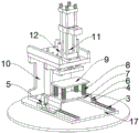
Fig. 1 is a schematic view of the overall structure of the present invention.
Fig. 2 is a schematic structural view of the inner side of the bottom support frame of the present invention.
Fig. 3 is a schematic view of a partial structure of the connection frame of the present invention.
Fig. 4 is a schematic view of a partial cross-sectional structure of the connection frame of the present invention.
In the figure: 1. an outer protective cover; 2. a bottom support frame; 3. a slide plate; 4. a buffer mechanism; 5. a locking lever; 6. a sliding plate; 7. a guide post; 8. a support spring; 9. a buffer plate; 10. a connecting frame; 11. a hydraulic cylinder; 12. adjusting a rod; 13. a height support block; 14. an adjusting sleeve; 15. connecting blocks; 16. positioning a forming block; 17. a connecting plate; 18. and a limiting plate.
Detailed Description
The technical solutions in the embodiments of the present invention will be described clearly and completely with reference to the accompanying drawings in the embodiments of the present invention, and it is obvious that the described embodiments are only some embodiments of the present invention, not all embodiments.
Referring to fig. 1 to 4, the present invention provides an embodiment: the utility model provides a design tool based on VR technique, includes bottom sprag frame 2, and outside protection casing 1 is installed to bottom sprag frame 2's up end, and the outside of outside protection casing 1 is provided with operation window, can carry out the clamping and take out the work piece through operation window, and is convenient for observe, and connecting plate 17 is installed to outside protection casing 1's inboard, and connecting block 15 is installed to the lower terminal surface of connecting plate 17, and two slides 3 are installed to the up end of connecting plate 17, and buffer gear 4 is installed to the up end of slide 3.
The buffer mechanism 4 comprises a locking rod 5, a sliding plate 6, guide posts 7, support springs 8 and buffer plates 9, the sliding plate 6 is installed on the outer side of the lower end of the locking rod 5, four support springs 8 are installed on the upper end face of the sliding plate 6, the guide posts 7 are installed on the inner sides of the support springs 8, the guide posts 7 play a role in guiding the descending process of the buffer plates 9, the buffer plate 9 is installed on the upper end face of one support spring 8, the buffer plates 9 can be driven by the support springs 8 to play a role in buffering, a height support block 13 is installed on the buffer plates 9 in a bent manner to prevent the deflection, two limiting plates 18 are installed on the upper end face of the height support block 13, a positioning forming block 16 is installed on the upper end face of one limiting plate 18, a connecting frame 10 is installed above the positioning forming block 16, the operation process is controlled in real time, the production efficiency is improved.
The hydraulic cylinder 11 is installed on the upper end face of the connecting frame 10, two adjusting rods 12 are installed on the outer sides of the hydraulic cylinder 11, adjusting sleeves 14 are installed on the outer sides of the bottom ends of the adjusting rods 12, the height of the height supporting block 13 can be adjusted through the adjusting rods 12, and therefore the connecting frame is suitable for workpieces with different sizes.
The external protective cover 1 is fixed on the upper end face of the bottom support frame 2 through screw connection, an operation window is arranged on the outer side of the external protective cover 1, a workpiece can be clamped and taken out through the operation window, and observation is facilitated.
The link 10 passes through the screwed connection to be fixed at the up end of connecting plate 17, and the lower extreme welded fastening of connecting plate 17 has connecting block 15, and the lower extreme of connecting block 15 extends to the inboard of bottom sprag frame 2 upper end, and accessible connecting block 15 is whole to be rotated, is convenient for observe the structure at different positions.
The limiting plate 18 is welded and fixed on the upper end face of the height supporting block 13, and the upper end faces of the height supporting block 13 and the positioning forming block 16 are provided with guide holes, so that the workpiece can be shaped and punched, and the workpiece can be taken out conveniently.
The working principle is as follows: when the device is used, whether the functions of all parts are intact is checked, the connecting block 15 is fixedly welded on the lower end face of the connecting plate 17, the lower end of the connecting block 15 extends to the inner side of the upper end of the bottom support frame 2, so that the integral structure can be operated conveniently, the angle can be rotated, the camera is arranged on the inner side of the bottom support frame 2, the operation process of the inner side of the bottom support frame 2 is monitored through the camera, the sliding groove is arranged on the upper section of the sliding plate 3, the lower end of the sliding plate 6 extends to the inner side of the sliding groove, the height of the height support block 13 is adjusted according to the size of a production workpiece, specifically, the adjusting sleeve 14 is fixedly welded on the inner side of the upper end of the connecting frame 10, the inner side of the adjusting sleeve 14 is provided with threads, the adjusting rod 12 is fixedly connected on the inner side of the adjusting, the workpiece is placed on the upper end face of the positioning forming block 16, the power supply is switched on, the hydraulic oil cylinder 11 is started, then the lower end of the hydraulic oil cylinder 11 forms a finished product through stamping operation on the workpiece, the limiting plate 18 is welded and fixed on the upper end face of the height supporting block 13, the positioning forming block 16 can be limited, deviation is prevented, after operation is completed, the supporting spring 8 drives the buffer plate 9 to buffer the workpiece, and finished product quality is improved conveniently.
It is obvious to a person skilled in the art that the invention is not restricted to details of the above-described exemplary embodiments, but that it can be implemented in other specific forms without departing from the spirit or essential characteristics of the invention. The present embodiments are therefore to be considered in all respects as illustrative and not restrictive, the scope of the invention being indicated by the appended claims rather than by the foregoing description, and all changes which come within the meaning and range of equivalency of the claims are therefore intended to be embraced therein. Any reference sign in a claim should not be construed as limiting the claim concerned.
Claims (7)
1. The utility model provides a design tool based on VR technique, includes bottom sprag frame (2), its characterized in that: an external protection cover (1) is installed on the upper end face of the bottom support frame (2), a connecting plate (17) is installed on the inner side of the external protection cover (1), a connecting block (15) is installed on the lower end face of the connecting plate (17), two sliding plates (3) are installed on the upper end face of the connecting plate (17), and a buffer mechanism (4) is installed on the upper end face of each sliding plate (3);
buffer gear (4) include check lock lever (5), sliding plate (6), guide post (7), supporting spring (8) and buffer board (9), sliding plate (6) are installed in the outside of check lock lever (5) lower extreme, four supporting spring (8) are installed to the up end of sliding plate (6), guide post (7) are installed to the inboard of supporting spring (8), one of them buffer board (9) are installed to the up end of supporting spring (8), high supporting shoe (13) are installed to bowing on buffer board (9), two limiting plate (18) are installed to the up end of high supporting shoe (13), one of them location shaping piece (16) are installed to the up end of limiting plate (18), link (10) are installed to the top of location shaping piece (16).
2. The VR technology-based design fixture of claim 1, wherein: the hydraulic oil cylinder (11) is installed on the upper end face of the connecting frame (10), two adjusting rods (12) are installed on the outer sides of the hydraulic oil cylinder (11), and adjusting sleeves (14) are installed on the outer sides of the bottom ends of the adjusting rods (12).
3. The VR technology-based design fixture of claim 1, wherein: the outer protective cover (1) is fixed on the upper end face of the bottom supporting frame (2) through screw connection, and an operation window is arranged on the outer side of the outer protective cover (1).
4. The VR technology-based design fixture of claim 1, wherein: the sliding plate (3) is fixedly connected to the upper end face of the connecting plate (17) through screws, a sliding groove is formed in the upper end face of the sliding plate (3), the lower end of the sliding plate (6) extends to the inner side of the sliding groove, and the sliding plate (6) is fixedly connected with the connecting plate (17) through a locking rod (5).
5. The VR technology-based design fixture of claim 1, wherein: the buffer plate (9) is connected with the sliding plate (6) through a supporting spring (8), and the upper end of the guide column (7) is connected and fixed on the lower end face of the buffer plate (9) through a screw.
6. The VR technology-based design fixture of claim 1, wherein: the connecting frame (10) is fixed on the upper end face of the connecting plate (17) through screw connection, the lower end of the connecting plate (17) is fixedly welded with a connecting block (15), and the lower end of the connecting block (15) extends to the inner side of the upper end of the bottom supporting frame (2).
7. The VR technology-based design fixture of claim 1, wherein: the limiting plate (18) is fixed on the upper end face of the height supporting block (13) in a welding mode, and guide holes are formed in the upper end faces of the height supporting block (13) and the positioning forming block (16).
Priority Applications (1)
| Application Number | Priority Date | Filing Date | Title |
|---|---|---|---|
| CN202020149993.XU CN211839716U (en) | 2020-02-03 | 2020-02-03 | Design tool based on VR technique |
Applications Claiming Priority (1)
| Application Number | Priority Date | Filing Date | Title |
|---|---|---|---|
| CN202020149993.XU CN211839716U (en) | 2020-02-03 | 2020-02-03 | Design tool based on VR technique |
Publications (1)
| Publication Number | Publication Date |
|---|---|
| CN211839716U true CN211839716U (en) | 2020-11-03 |
Family
ID=73232582
Family Applications (1)
| Application Number | Title | Priority Date | Filing Date |
|---|---|---|---|
| CN202020149993.XU Active CN211839716U (en) | 2020-02-03 | 2020-02-03 | Design tool based on VR technique |
Country Status (1)
| Country | Link |
|---|---|
| CN (1) | CN211839716U (en) |
Cited By (1)
| Publication number | Priority date | Publication date | Assignee | Title |
|---|---|---|---|---|
| CN113664109A (en) * | 2021-08-26 | 2021-11-19 | 德清精诚制药机械有限公司 | A tool for high-speed high-efficient processing is towards cap |
-
2020
- 2020-02-03 CN CN202020149993.XU patent/CN211839716U/en active Active
Cited By (1)
| Publication number | Priority date | Publication date | Assignee | Title |
|---|---|---|---|---|
| CN113664109A (en) * | 2021-08-26 | 2021-11-19 | 德清精诚制药机械有限公司 | A tool for high-speed high-efficient processing is towards cap |
Similar Documents
| Publication | Publication Date | Title |
|---|---|---|
| CN211839716U (en) | Design tool based on VR technique | |
| CN208791486U (en) | A kind of fixation device on glass cutting machine | |
| CN201446716U (en) | Single-rod hydraulic transmission mechanism used on tensile machine | |
| CN213378750U (en) | Bottom plate unloading conveying mechanism | |
| CN210253817U (en) | High-efficient rotary fixture of punching machine | |
| CN101015843A (en) | Upper roll hydraulic holding-down device of hydraulic three-roll plate bending machine and framework thereof | |
| CN107414554B (en) | Double-inclined-hole drilling equipment for numerical control machining center | |
| CN214722488U (en) | Machining tool for hydraulic oil pump casting for automobile | |
| CN214685228U (en) | Car installing support processing frock | |
| CN210412135U (en) | Barrel multi-hole side punching die | |
| CN211072740U (en) | Multi-step positioning fixture | |
| CN213917972U (en) | Adjustable fixing device for industrial manipulator | |
| CN217597074U (en) | Rack is used in mould steel production | |
| CN217142013U (en) | Fixing device capable of finely adjusting multi-station fine blanking die | |
| CN208643756U (en) | A kind of numerical control bender | |
| CN220277966U (en) | Simple bending mechanism | |
| CN220216597U (en) | Automobile nut cold heading equipment | |
| CN210706218U (en) | Guide mechanism for slide block of servo hydraulic press | |
| CN217369878U (en) | Metal plate bending device | |
| CN220348369U (en) | Positioner is used in hardware processing | |
| CN211112260U (en) | Small box clamp tightening and loosening mechanism | |
| CN210257391U (en) | C-shaped servo high-speed numerical control punch | |
| CN203679827U (en) | Tooling device for machining power output end of steering system shell | |
| CN213033317U (en) | Metal bender of office furniture production usefulness | |
| CN216801469U (en) | Car seat skeleton bending device with direction function |
Legal Events
| Date | Code | Title | Description |
|---|---|---|---|
| GR01 | Patent grant | ||
| GR01 | Patent grant |