CN211823619U - Anti-adhesion rotating cage drying machine - Google Patents
Anti-adhesion rotating cage drying machine Download PDFInfo
- Publication number
- CN211823619U CN211823619U CN202020044188.0U CN202020044188U CN211823619U CN 211823619 U CN211823619 U CN 211823619U CN 202020044188 U CN202020044188 U CN 202020044188U CN 211823619 U CN211823619 U CN 211823619U
- Authority
- CN
- China
- Prior art keywords
- drying cylinder
- air
- fixedly connected
- motor
- pipe
- Prior art date
- Legal status (The legal status is an assumption and is not a legal conclusion. Google has not performed a legal analysis and makes no representation as to the accuracy of the status listed.)
- Active
Links
Images


Abstract
The utility model discloses an anti-adhesion rotating cage dryer, which adopts the technical proposal that the dryer comprises a main body plate, the upper surface of the main body plate is fixedly connected with four supporting legs, the top ends of the supporting legs are fixedly connected with a drying cylinder, a feeding pipe is arranged in the feeding port of the drying cylinder, the top end of the drying cylinder is fixedly connected with a second motor, the rotary cage is driven by the second motor to rotate, the soft capsules are scattered by a rotating cage, the scattered soft capsules are dried by an electric heating pipe, the dried soft capsules are stirred by a stirring plate, so that the soft capsules are heated more uniformly, meanwhile, the soft capsules are prevented from being bonded together, the damp and hot air generated in the drying process is treated by a heat circulating device, and the processed dry hot air is conveyed into the drying cylinder again, and the dried soft capsules are sterilized by an ultraviolet sterilizing lamp.
Description
Technical Field
The utility model relates to a dry technical field of rotating cage specifically is an antiseized knot rotating cage desiccator.
Background
At present, in the processing process of soft capsules, after the soft capsules are pressed and conveyed to a conveying belt, the conveying belt conveys the soft capsules to the end parts, the soft capsules fall into a feeding hopper below the end parts of the conveying belt, and then the soft capsules are conveyed into a drying rotating cage by the feeding hopper to be air-dried and shaped. Because the soft capsule has certain temperature during pressing, the surface of the soft capsule has viscosity, and the soft capsule is easy to stick together when being dried in a rotating cage, so that the drying is incomplete.
SUMMERY OF THE UTILITY MODEL
In view of the problem that exists among the prior art, the utility model discloses an antiseized knot cage desiccator, the technical scheme of adoption is, including the main part board, its characterized in that: the upper surface of the main body plate is fixedly connected with four supporting legs, the top ends of the supporting legs are fixedly connected with a drying cylinder, an inlet pipe is installed in an inlet of the drying cylinder, the top end of the drying cylinder is fixedly connected with a second motor, a motor shaft of the second motor penetrates through the drying cylinder to be fixedly connected with a cross-shaped fixing plate, the cross-shaped fixing plate is fixedly connected with the inner surface of a rotating cage, the inner surface of the drying cylinder is fixedly connected with an electric heating pipe, the position of the electric heating pipe corresponds to the position of the rotating cage, a driving rod is connected in the drying cylinder in a rotating mode, the top end of the driving rod is located in the rotating cage and is rotatably connected with the rotating cage, the low end of the driving rod penetrates through the drying cylinder to be connected with a first motor, the first motor is located on the drying cylinder and is fixedly connected with the drying cylinder, a pushing plate is fixedly connected with the driving rod, the internal surface fixedly connected with sterilamp of a drying section of thick bamboo, sterilamp is located the upside of pushing plate, the gas outlet and the air inlet of thermal cycle device of a drying section of thick bamboo are connected, thermal cycle device's gas outlet is connected with the air inlet of a drying section of thick bamboo, thermal cycle device is located main part board and fixed connection, be equipped with two bin outlets on the drying section of thick bamboo, fixedly connected with arranges the bin pipe in the bin outlet, install switch group on the main part board, switch group's input is connected with external power source's output, switch group's output and first motor, second motor, thermal cycle device, electric heating pipe and sterilamp's input electricity are connected.
As an optimal technical scheme of the utility model, thermal cycle device includes air heater, air filter, dehumidifier and air extractor, air heater, air filter, dehumidifier and air extractor all are located the main part board and fixed connection, the air inlet of air extractor is connected with the gas outlet of dryer through taking out from the pipe, the gas outlet of air extractor is connected with the air inlet of dehumidifier through the fourth conveyer pipe, the gas outlet of dehumidifier is connected with air filter's air inlet through the third conveyer pipe, air filter's gas outlet is connected with air heater's air inlet through the second conveyer pipe, air heater's gas outlet is connected with the air inlet of dryer through first conveyer pipe.
As an optimal technical scheme of the utility model, the fixed surface is connected with temperature sensor in the top of a dry section of thick bamboo, temperature sensor's output is connected with the input electricity of singlechip, switch group's output is connected with the input electricity of temperature sensor and singlechip.
As the utility model discloses a preferred technical scheme, the internal fixed surface of drying cylinder is connected with the filter, the filter is located sterilamp's upside, the filter rotates with the drive pole to be connected, fixedly connected with scraper blade on the drive pole, the low side of scraper blade is connected with the last surface contact of filter.
As a preferred technical scheme of the utility model, be equipped with the recess on the main part board, sliding connection has the box that holds in the recess, hold two handles of fixedly connected with on the box.
The utility model has the advantages that: the utility model discloses a second motor drives the rotating cage and rotates, break up the softgel through the rotating cage, it dries to falling the bag through the soft of electric heating pipe after breaking up, soft capsule when drying is stirred through stirring the board and is stirred, it is more even to make the softgel be heated, avoid the softgel to bond together simultaneously, the damp and hot air that produces during the drying, handle damp and hot air through thermal cycle device, and carry the dry steam after will handling again to the drying section of thick bamboo in, carry out germicidal treatment through sterilamp to the softgel after drying.
Drawings
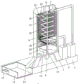
FIG. 1 is a schematic structural view of the present invention;
fig. 2 is a sectional view of the present invention;
fig. 3 is a schematic structural view of the thermal cycling apparatus of the present invention.
In the figure: 1-main body plate, 2-supporting legs, 3-thermal cycle device, 301-first delivery pipe, 302-extraction pipe, 303-air heater, 304-air filter, 305-second delivery pipe, 306-third delivery pipe, 307-dehumidifier, 308-fourth delivery pipe, 309-air extractor, 4-first motor, 5-single chip microcomputer, 6-power switch group, 7-feeding pipe, 8-second motor, 9-drying cylinder, 10-discharging pipe, 11-material containing box, 12-grip, 13-push plate, 14-driving rod, 15-cross fixing plate, 16-rotating cage, 17-electric heating pipe, 18-stirring plate, 19-scraping plate, 20-filtering plate, 21-ultraviolet germicidal lamp, 22-temperature sensor.
Detailed Description
Example 1
As shown in fig. 1, fig. 2 and fig. 3, the utility model discloses an antiseized knot cage desiccator, the technical scheme of adoption is, including main part board 1, its characterized in that: the upper surface of the main body plate 1 is fixedly connected with four supporting legs 2, the top end of each supporting leg 2 is fixedly connected with a drying cylinder 9, an inlet pipe 7 is installed in a feeding port of the drying cylinder 9, the top end of the drying cylinder 9 is fixedly connected with a second motor 8, a motor shaft of the second motor 8 penetrates through the drying cylinder 9 and a cross-shaped fixing plate 15 to be fixedly connected, the cross-shaped fixing plate 15 is fixedly connected with the inner surface of a rotating cage 16, the inner surface of the drying cylinder 9 is fixedly connected with an electric heating pipe 17, the position of the electric heating pipe 17 corresponds to the position of the rotating cage 16, a driving rod 14 is rotatably connected in the drying cylinder 9, the top end of the driving rod 14 is located in the rotating cage 16, the driving rod 14 is rotatably connected with the rotating cage 16, the low end of the driving rod 14 penetrates through the drying cylinder 9 to be connected with a first motor 4, the first motor 4 is located, fixedly connected with push plate 13 on drive pole 14, the low side of push plate 13 is connected with the low side internal surface contact of a drying section of thick bamboo 9, the internal surface fixed connection of a drying section of thick bamboo 9 sterilamp 21, sterilamp 21 is located the upside of push plate 13, the gas outlet of a drying section of thick bamboo 9 is connected with heat cycle device 3's air inlet, heat cycle device 3's gas outlet is connected with the air inlet of a drying section of thick bamboo 9, heat cycle device 3 is located main part board 1 and fixed connection, be equipped with two bin outlets on a drying section of thick bamboo 9, fixedly connected with bin outlet 10 in the bin outlet, install switch group 6 on the main part board 1, switch group 6's input is connected with external power source's output, switch group 6's output and first motor 4, second motor 8, heat cycle device 3, The electric heating tube 17 is electrically connected with the input end of the ultraviolet germicidal lamp 21, and the power switch group 6 is provided with switch buttons which are in one-to-one correspondence with the first motor 4, the second motor 8, the heat circulating device 3, the electric heating tube 17 and the ultraviolet germicidal lamp 21.
As a preferred technical scheme of the utility model, thermal cycle device 3 includes air heater 303, air filter 304, dehumidifier 307 and air extractor 309, air heater 303, air filter 304, dehumidifier 307 and air extractor 309 all are located main part board 1 and fixed connection, the air inlet of air extractor 309 is connected with the gas outlet of drying cylinder 9 through taking out from pipe 302, the gas outlet of air extractor 309 is connected with the air inlet of dehumidifier 307 through fourth conveyer pipe 308, the gas outlet of dehumidifier 307 is connected with the air inlet of air filter 304 through third conveyer pipe 306, the gas outlet of air filter 304 is connected with the air inlet of air heater 303 through second conveyer pipe 305, the gas outlet of air heater 303 is connected with the air inlet of drying cylinder 9 through first conveyer pipe 301.
As an optimal technical scheme of the utility model, the fixed surface is connected with temperature sensor 22 in the top of a drying section of thick bamboo 9, temperature sensor 22's output is connected with singlechip 5's input electricity, switch block 6's output is connected with temperature sensor 22 and singlechip 5's input electricity, and this singlechip 5 is 89C51 chip, and this singlechip 5 is widely used, and this field technical staff of concrete connection mode of pin can refer to the technical manual according to actual need and learn, belongs to common general knowledge.
As the utility model discloses a preferred technical scheme, the internal fixed surface of drying cylinder 9 is connected with filter 20, filter 20 is located sterilamp 21's upside, filter 20 rotates with drive pole 14 to be connected, drive fixedly connected with scraper blade 19 on the pole 14, the low side of scraper blade 19 is connected with the last surface contact of filter 20.
As an optimized technical scheme of the utility model, be equipped with the recess on the main part board 1, sliding connection has the box 11 that holds in the recess, hold two handles 12 of fixedly connected with on the box 11.
The utility model discloses a theory of operation: a worker puts soft capsules to be dried into a rotary cage 16 through a feeding pipe 7, the temperature in a drying cylinder 9 is increased through an electric heating pipe 17, the soft capsules in the rotary cage 16 are dried through the electric heating pipe 17, a second motor 8 drives the rotary cage 16 to rotate through a cross fixing plate 15, the soft capsules in the rotary cage 16 are scattered through the rotation of the rotary cage 16, the soft capsules are prevented from being heated unevenly, a first motor 4 drives an agitating plate 18 to rotate through a driving rod 14, the soft capsules in the rotary cage 16 are agitated through the agitating plate 18, the soft capsules are heated evenly, the soft capsules are prevented from being bonded when being heated, the dried soft capsules fall onto a filter plate 20 through a through groove at the bottom of the rotary cage 16, hot and humid air generated when the soft capsules are dried is extracted through an air extractor 309, and the extracted hot and humid air is conveyed into a dehumidifier 307 to be dehumidified, and carry the air after the dehumidification to air filter 304 in, filter the air after the dehumidification through air filter 304, avoid remaining impurity in the air, influence the stoving effect of soft capsule, filtered air enters into air heater 303 and heats, and carry the air after the heating to in drying cylinder 9, drive pole 14 through the drive and drive scraper blade 19 and rotate, promote the soft capsule on filter 20 through scraper blade 19, break up for the second time, avoid having the phenomenon of bonding in the soft capsule, drive push plate 13 through drive pole 14 and rotate, through pushing plate 13 with the propelling movement of the back soft capsule after drying to arrange in expecting the pipe 10 and get rid of, collect through flourishing magazine 11, make things convenient for the staff to take flourishing magazine 11 through handle 12.
The utility model relates to a circuit connection is the conventional means that technical staff adopted in this field, and accessible limited number of tests obtains the technological inspiration, belongs to the widely used prior art.
Components not described in detail herein are prior art.
Although the present invention has been described in detail with reference to the specific embodiments, the present invention is not limited to the above embodiments, and various changes can be made without departing from the spirit of the present invention within the knowledge range of those skilled in the art, and modifications or variations without creative efforts are still within the scope of the present invention.
Claims (5)
1. The utility model provides an antiseized knot cage desiccator, includes main part board (1), its characterized in that: the upper surface of main part board (1) is fixedly connected with four supporting legs (2), the top fixedly connected with drying cylinder (9) of supporting leg (2), install inlet pipe (7) in the feed inlet of drying cylinder (9), the top fixedly connected with second motor (8) of drying cylinder (9), the motor shaft of second motor (8) passes drying cylinder (9) and cross fixed plate (15) fixed connection, the internal surface fixed connection of cross fixed plate (15) and rotating cage (16), the internal surface fixed connection of drying cylinder (9) is connected with electric heating pipe (17), the position of electric heating pipe (17) is corresponding with the position of rotating cage (16), drying cylinder (9) internal rotation is connected with drive pole (14), the top of drive pole (14) is located rotating cage (16), and drive pole (14) and rotating cage (16) rotate and are connected, the low end of driving rod (14) passes through drying cylinder (9) and is connected with first motor (4), first motor (4) is located drying cylinder (9) and fixed connection, fixedly connected with push plate (13) is gone up in driving rod (14), the low end of push plate (13) is connected with the low end internal surface contact of drying cylinder (9), the internal surface fixed connection of drying cylinder (9) has sterilamp (21), sterilamp (21) are located the upside of push plate (13), the gas outlet and the air inlet of thermal cycle device (3) of drying cylinder (9) are connected, the gas outlet and the air inlet of drying cylinder (9) of thermal cycle device (3) are connected, thermal cycle device (3) are located main part board (1) and fixed connection, be equipped with two bin outlets on drying cylinder (9), fixedly connected with bin outlet (10) in the bin outlet, install switch group (6) on main part board (1), the input of switch group (6) is connected with external power source's output, the output of switch group (6) is connected with the input electricity of first motor (4), second motor (8), thermal cycle device (3), electric heating pipe (17) and sterilamp (21).
2. An anti-bonding rotary cage dryer as claimed in claim 1, wherein: the heat circulating device (3) comprises an air heater (303), an air filter (304), a dehumidifier (307) and an air extractor (309), the air heater (303), the air filter (304), the dehumidifier (307) and the air extractor (309) are all positioned on the main body plate (1) and are fixedly connected, the air inlet of the air pump (309) is connected with the air outlet of the drying cylinder (9) through the pumping-out pipe (302), the air outlet of the air pump (309) is connected with the air inlet of the dehumidifier (307) through a fourth delivery pipe (308), the air outlet of the dehumidifier (307) is connected with the air inlet of the air filter (304) through a third delivery pipe (306), the air outlet of the air filter (304) is connected with the air inlet of the air heater (303) through a second conveying pipe (305), the air outlet of the air heater (303) is connected with the air inlet of the drying cylinder (9) through a first conveying pipe (301).
3. An anti-bonding rotary cage dryer as claimed in claim 1, wherein: the top internal surface fixed connection of drying cylinder (9) has temperature sensor (22), the output of temperature sensor (22) is connected with the input electricity of singlechip (5), the output of switch group (6) is connected with the input electricity of temperature sensor (22) and singlechip (5).
4. An anti-bonding rotary cage dryer as claimed in claim 1, wherein: the inner surface of the drying cylinder (9) is fixedly connected with a filter plate (20), the filter plate (20) is positioned on the upper side of an ultraviolet germicidal lamp (21), the filter plate (20) is rotatably connected with a driving rod (14), the driving rod (14) is fixedly connected with a scraper (19), and the lower end of the scraper (19) is connected with the upper surface of the filter plate (20) in a contact manner.
5. An anti-bonding rotary cage dryer as claimed in claim 1, wherein: the novel multifunctional table is characterized in that a groove is formed in the main body plate (1), a containing box (11) is connected in the groove in a sliding mode, and two handles (12) are fixedly connected to the containing box (11).
Priority Applications (1)
| Application Number | Priority Date | Filing Date | Title |
|---|---|---|---|
| CN202020044188.0U CN211823619U (en) | 2020-01-09 | 2020-01-09 | Anti-adhesion rotating cage drying machine |
Applications Claiming Priority (1)
| Application Number | Priority Date | Filing Date | Title |
|---|---|---|---|
| CN202020044188.0U CN211823619U (en) | 2020-01-09 | 2020-01-09 | Anti-adhesion rotating cage drying machine |
Publications (1)
| Publication Number | Publication Date |
|---|---|
| CN211823619U true CN211823619U (en) | 2020-10-30 |
Family
ID=73050339
Family Applications (1)
| Application Number | Title | Priority Date | Filing Date |
|---|---|---|---|
| CN202020044188.0U Active CN211823619U (en) | 2020-01-09 | 2020-01-09 | Anti-adhesion rotating cage drying machine |
Country Status (1)
| Country | Link |
|---|---|
| CN (1) | CN211823619U (en) |
Cited By (1)
| Publication number | Priority date | Publication date | Assignee | Title |
|---|---|---|---|---|
| CN113577334A (en) * | 2021-08-04 | 2021-11-02 | 广东亚北农副产品有限公司 | Pueraria freeze-dried powder raw material pre-disinfection device and using method thereof |
-
2020
- 2020-01-09 CN CN202020044188.0U patent/CN211823619U/en active Active
Cited By (1)
| Publication number | Priority date | Publication date | Assignee | Title |
|---|---|---|---|---|
| CN113577334A (en) * | 2021-08-04 | 2021-11-02 | 广东亚北农副产品有限公司 | Pueraria freeze-dried powder raw material pre-disinfection device and using method thereof |
Similar Documents
| Publication | Publication Date | Title |
|---|---|---|
| CN106382808A (en) | Heat recycling type efficient medicinal material drying device | |
| CN108224982A (en) | A kind of bamboo material drying unit of intermittent delivery | |
| CN211823619U (en) | Anti-adhesion rotating cage drying machine | |
| CN209485017U (en) | Agalloch eaglewood material negative pressure stirring and drying machine | |
| CN212227655U (en) | Seed drying device for agricultural | |
| CN107906855A (en) | A kind of biological particles production dryer | |
| CN219494675U (en) | Environment-friendly powder coating drying mechanism | |
| CN208269583U (en) | A kind of drying tank for tea processing | |
| CN207806142U (en) | A kind of automatic rinser and its drying unit | |
| CN109163530B (en) | Biological feed drying device | |
| CN210663762U (en) | Energy-efficient textile product drying device | |
| CN207439064U (en) | A kind of processing of crude drugs high-temperature hot-air cycles oven | |
| CN209726752U (en) | A kind of desiccant process units with circulation drying function | |
| CN213020780U (en) | Multilayer rotating disc type dryer | |
| CN208704386U (en) | A kind of concrete drier of industrial production | |
| CN220018018U (en) | Drying device for polyester sheet | |
| CN220750700U (en) | Novel belt dryer | |
| CN109099657A (en) | A kind of mobile drying device of bamboo and wood processing | |
| CN215260815U (en) | Bi-directional stirring double-cone rotary vacuum dryer | |
| CN219076213U (en) | Drying device of automatic material sucking machine for plastic processing | |
| CN216924988U (en) | Drying device is used in processing of soybean protein isolate powder | |
| CN208832875U (en) | A kind of mobile drying device of bamboo and wood processing | |
| CN106766761A (en) | A kind of root of kudzu vine roller drying machine | |
| CN109329477A (en) | It is a kind of rubbed for dark green tea after drying device | |
| CN219103565U (en) | Air flow dryer for gypsum production by using circulating air heater |
Legal Events
| Date | Code | Title | Description |
|---|---|---|---|
| GR01 | Patent grant | ||
| GR01 | Patent grant |