CN211822776U - Wall-hung type cabinet air conditioner - Google Patents
Wall-hung type cabinet air conditioner Download PDFInfo
- Publication number
- CN211822776U CN211822776U CN202020094300.1U CN202020094300U CN211822776U CN 211822776 U CN211822776 U CN 211822776U CN 202020094300 U CN202020094300 U CN 202020094300U CN 211822776 U CN211822776 U CN 211822776U
- Authority
- CN
- China
- Prior art keywords
- wall
- air
- air conditioner
- front panel
- plate
- Prior art date
- Legal status (The legal status is an assumption and is not a legal conclusion. Google has not performed a legal analysis and makes no representation as to the accuracy of the status listed.)
- Active
Links
- 230000007246 mechanism Effects 0.000 claims abstract description 14
- XLYOFNOQVPJJNP-UHFFFAOYSA-N water Substances O XLYOFNOQVPJJNP-UHFFFAOYSA-N 0.000 claims description 23
- 238000001746 injection moulding Methods 0.000 claims description 5
- 230000007704 transition Effects 0.000 claims description 3
- 238000009434 installation Methods 0.000 abstract description 8
- 238000004378 air conditioning Methods 0.000 description 9
- 238000010438 heat treatment Methods 0.000 description 3
- 239000000243 solution Substances 0.000 description 3
- 238000005452 bending Methods 0.000 description 2
- 238000012423 maintenance Methods 0.000 description 2
- 230000004048 modification Effects 0.000 description 2
- 238000012986 modification Methods 0.000 description 2
- 230000009471 action Effects 0.000 description 1
- 230000009286 beneficial effect Effects 0.000 description 1
- 239000012141 concentrate Substances 0.000 description 1
- 238000010586 diagram Methods 0.000 description 1
- 230000006872 improvement Effects 0.000 description 1
- 239000002184 metal Substances 0.000 description 1
- 238000000465 moulding Methods 0.000 description 1
- 230000009467 reduction Effects 0.000 description 1
- 238000005057 refrigeration Methods 0.000 description 1
- 238000006467 substitution reaction Methods 0.000 description 1
Images





Landscapes
- Air Filters, Heat-Exchange Apparatuses, And Housings Of Air-Conditioning Units (AREA)
Abstract
The utility model provides a wall-hung type cabinet air conditioner, wall-hung type cabinet air conditioner includes casing, wind channel device, fan, wind channel worm tongue, horizontal swing leaf mechanism, heat exchanger, electrical apparatus and hangs the wall support, and horizontal swing leaf mechanism is located between the front end of wind-guiding portion and the fan, hangs the wall support and is used for linking firmly with the wall with the casing postnotum in order to hang wall-hung type cabinet air conditioner and install on the wall. The utility model discloses a wall-hung type cabinet air conditioner, the shell of which extends vertically, the air outlet is arranged vertically, and a wall-hung bracket is configured to install the wall-hung type cabinet air conditioner on the wall in a hanging way; the horizontal swing blade mechanism of the cabinet air conditioner is positioned between the front end of the volute air guide part of the air duct device and the fan, so that the whole volume of the air duct device is reduced, the whole volume of an indoor unit is reduced, and wall-mounted installation is facilitated.
Description
Technical Field
The utility model belongs to the technical field of air conditioning equipment, especially, relate to a wall-hung type cabinet air conditioner (also called hanging vertical air conditioning indoor set) and have its air conditioner.
Background
The split air conditioner is one kind of air conditioning equipment, and consists of indoor unit and outdoor unit installed separately inside and outside the room and connected via pipeline and wire. The indoor unit of the split air conditioner is classified into various types, such as a wall-hung type, a vertical cabinet type, a ceiling type, an embedded type and a floor type, wherein the indoor unit of the household split air conditioner is commonly used in the wall-hung type and the vertical cabinet type.
The wall-hung type air conditioner indoor unit is usually transversely installed at a higher position on an indoor wall, does not occupy the floor space, and is popular among many users. When the indoor unit is installed, a certain distance is usually required to be kept away from the top and two side walls of a room to prevent air circulation from being blocked, and when the installation position of the indoor unit is selected, a place which is easy to drain and can be connected with an outdoor unit pipeline, a place without valuables such as a television, a computer and the like below and a place where an air outlet is not directly blown to a user are considered to be selected. And in some spaces, adopt horizontal installation can not make full use of indoor space to inconvenient maintenance and maintenance at ordinary times, and from top to bottom air supply usually, because the restriction of indoor floor height and wall bearing, lead to its refrigeration heating ability and air supply scope less, and the air supply scope concentrates on the below of its mounted position, is unfavorable for the circulation of room air, leads to indoor temperature distribution unbalance, and user's comfort is relatively poor.
For the vertical type floor installation of the vertical type air-conditioning indoor unit, the heat exchanger with larger size can be adopted without considering the wall bearing, and the large-range air supply can be realized, so that the refrigerating and heating capacity of the vertical type air-conditioning indoor unit is higher than that of a wall-hung air-conditioning indoor unit. However, the volume is large, so that the occupied space is large and the requirement on the installation space is high. In order to reduce the occupation of the indoor space, the indoor unit of the vertical cabinet air conditioner is usually arranged close to the wall or the corner, and the air is fed from the side part and is discharged from the front part.
How to design a wall-mounted cabinet air conditioner which has high refrigerating and heating capacity compared with the wall-mounted indoor air conditioner transversely installed in the prior art and saves the occupied space compared with the floor-type vertical cabinet air conditioner indoor unit in the prior art is a key improvement direction of air conditioners by a plurality of air conditioner manufacturers at present.
The above information disclosed in this background section is only for enhancement of understanding of the background of the application and therefore it may comprise prior art that does not constitute known to a person of ordinary skill in the art.
SUMMERY OF THE UTILITY MODEL
The utility model discloses to the above-mentioned technical problem that machine exists in wall-hung type air conditioning indoor set and the vertical cabinet type air conditioning indoor set among the prior art, provide a wall-hung type cabinet air conditioner.
In order to solve the technical problem, the utility model adopts the following technical scheme to realize: a cabinet wall air conditioner comprising:
the air conditioner comprises a shell, a front panel, a rear panel, a front cover plate, a rear cover plate and a fan, wherein the shell is in a vertically extending column shape and comprises a front panel and a rear cover plate positioned on the rear side of the front panel, the front panel is provided with a vertically arranged air outlet, and the rear cover plate is provided with an air inlet and an air inlet grille;
the air channel device is arranged in the shell and comprises an upper supporting plate, a lower supporting plate and a volute positioned between the upper supporting plate and the lower supporting plate and connected with the upper supporting plate and the lower supporting plate, the volute comprises an air guide part communicated with the air inlet and an air outlet part communicated with the air outlet, and the front end of the air guide part is connected to the air outlet part;
the fan is arranged in the air duct device and used for driving indoor air to flow into the air duct device from the air inlet and flow towards the air outlet;
the air duct volute tongue is positioned between the air outlet part and the fan and is arranged opposite to the front end of the air guide part in the left-right direction;
the transverse swing blade mechanism is positioned between the front end of the air guide part and the fan and used for vertically adjusting the air outlet direction;
the heat exchanger is arranged on the air duct device and is used for carrying out heat exchange with indoor air flowing into the air duct device from the air inlet;
the electrical device is arranged in the shell and is positioned below the air duct device;
and the wall-mounted bracket is used for fixedly connecting the rear back plate with a wall so as to mount the wall-mounted cabinet air conditioner on the wall in a hanging manner.
The yaw blade mechanism includes:
the driving motor is arranged on the upper supporting plate, and an output shaft of the driving motor is vertically arranged;
a plurality of horizontal swinging blades which are sequentially arranged at intervals in the height direction of the air outlet part;
the connecting rod extends vertically and is close to the air outlet part, and each horizontal swinging blade is connected to the connecting rod;
and one end of the crank is fixedly connected with the output shaft of the driving motor, and the other end of the crank is fixedly connected with the top end of the connecting rod.
The side surface of the yaw blade facing the fan is an arc-shaped surface matched with the fan, and the arc-shaped surface is in smooth transition with other side surfaces of the yaw blade adjacent to the arc-shaped surface.
The air-out portion is vertically extended flat, be formed with wind channel air-out grid in the air-out portion, wind channel air-out grid includes a plurality of horizontal grid bars at least, the horizontal swing leaf with horizontal grid bar one-to-one just is located the dead astern of horizontal grid bar.
The air duct device is of an integrated injection molding structure.
The air duct device is detachably connected with the back plate, the front panel is detachably connected with the back plate and the air outlet portion, the front panel is combined with the back plate in a front-back mode, the upper supporting plate is attached to the inner wall of the front panel and the inner wall of the back plate, and the lower supporting plate is attached to the inner wall of the front panel and the inner wall of the back plate.
A drain hole for draining condensed water is formed on the lower supporting plate, a water receiving tray is arranged between the electrical device and the lower supporting plate, and the water receiving tray is attached to the inner wall of the front panel and the inner wall of the rear back plate.
The electrical device is obliquely arranged, and the left side surface and the right side surface of the electrical device are correspondingly and fixedly connected to the rear back plate.
The wall-hung type cabinet air conditioner still includes:
a display device arranged on the front panel and positioned at the left side part or the right side part of the air outlet;
the housing further includes:
the top cover is fixedly connected with the top end of the front panel and/or the back plate and used for closing the top end of the space between the front panel and the back plate;
the bottom plate is fixedly connected with the bottom end of the front panel and/or the rear back plate and used for closing the bottom end of the space between the front panel and the rear back plate;
the bottom plate and the top cover have the same structure and the same size.
Compared with the prior art, the wall-hung type cabinet air conditioner of the utility model has the advantages that the shell extends vertically, the air outlet is vertically arranged, and the wall-hung type cabinet air conditioner is arranged on the wall in a hanging way by the wall-hung bracket; the horizontal swing blade mechanism of the cabinet air conditioner is positioned between the front end of the volute air guide part of the air duct device and the fan, so that the whole volume of the air duct device is reduced, the whole volume of an indoor unit is reduced, and wall-mounted installation is facilitated.
Other features and advantages of the present invention will become more apparent from the following detailed description of the invention when read in conjunction with the accompanying drawings.
Drawings
In order to more clearly illustrate the technical solutions in the embodiments of the present invention, the drawings needed to be used in the embodiments will be briefly described below, and it is obvious that the drawings in the following description are some embodiments of the present invention, and it is obvious for those skilled in the art to obtain other drawings without creative efforts.
Fig. 1 is a schematic view of the front view structure of the wall-hung cabinet air conditioner of the present invention;
fig. 2 is a schematic view of the back view structure of the wall-hung cabinet air conditioner of the present invention;
FIG. 3 is a structural diagram of a back view angle of the wall-hung type cabinet air conditioner with a wall-hung bracket and a front panel omitted;
FIG. 4 is a sectional view taken along line A-A of FIG. 2 with the front panel omitted;
FIG. 5 is a view taken along line A of FIG. 3;
FIG. 6 is an enlarged view of the portion A of FIG. 5;
FIG. 7 is a sectional view taken along line B-B of FIG. 5;
fig. 8 is a schematic structural view of a viewing angle of the air duct device of the wall-hung cabinet air conditioner of the present invention;
fig. 9 is a schematic structural view of another view angle of the air duct device of the wall-hung cabinet air conditioner of the present invention;
FIG. 10 is an enlarged view of the portion A of FIG. 8;
fig. 11 is a schematic structural view of a wall-hung bracket of the wall-hung cabinet air conditioner of the present invention;
fig. 12 is a schematic view of a back plate of the wall-hung cabinet air conditioner according to the present invention;
fig. 13 is a schematic structural view of another viewing angle of the back plate of the wall-hung cabinet air conditioner of the present invention.
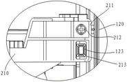
Reference numerals: 1. a wall-mounted cabinet air conditioner; 100. a housing; 110. a front panel; 111. an air outlet; 120. a back panel; 121. an air inlet; 122. an air inlet grille; 123. positioning the projection; 124. a drain hole; 125. a hanging part; 126. a middle section; 130. a display device; 140. a top cover; 150. a base plate; 200. an air duct device; 210. an upper supporting plate; 211. a lug; 212. screw holes; 213. positioning holes; 220. a lower supporting plate; 230. a volute; 231. a wind guide part; 232. an air outlet part; 233. an air outlet grille; 234. a transverse grid bar; 300. a fan; 400. an air duct volute tongue; 500. a leaf swinging mechanism; 510. 520, a yaw blade, 521, an arc-shaped surface; 530. a connecting rod; 540. a crank; 600. a heat exchanger; 700. an electrical device; 800. hanging a wall bracket; 810. a front end plate; 811. a hooking part; 820. a side plate; 821. a front portion; 822. a rear portion; 8221. a first planar portion; 8222. a second planar section; 900. a water pan.
Detailed Description
In order to make the objects, technical solutions and advantages of the present invention more apparent, the present invention will be described in further detail with reference to the accompanying drawings and embodiments.
It should be noted that in the description of the present invention, the terms of direction or positional relationship indicated by the terms "upper", "lower", "left", "right", "vertical", "horizontal", "inner", "outer", etc. are based on the directions or positional relationships shown in the drawings, which are merely for convenience of description, and do not indicate or imply that the device or element must have a specific orientation, be constructed and operated in a specific orientation, and thus, should not be construed as limiting the present invention.
In the description of the present invention, it is to be noted that, unless otherwise explicitly specified or limited, the terms "mounted," "connected," and "connected" are to be construed broadly, and may be, for example, fixedly connected, detachably connected, or integrally connected; can be mechanically or electrically connected; they may be connected directly or indirectly through intervening media, or they may be interconnected between two elements. The specific meaning of the above terms in the present invention can be understood in specific cases to those skilled in the art.
Referring to fig. 1 to 3, there is illustrated an exemplary wall-mounted cabinet air conditioner 1 including: the air duct device comprises a shell 100, an air duct device 200, a fan 300, an air duct volute tongue 400, a transverse swing blade mechanism 500, a heat exchanger 600, an electric device 700 and a wall-hung bracket 800. Wherein:
the air conditioner comprises a shell 100, a fan blade, a fan;
the air duct device 200 is arranged in the housing 100, and includes an upper support plate 210, a lower support plate 220 and a volute 230, wherein the volute 230 is used for guiding air flowing into the housing 100 from the air inlet 121 to the air outlet 111, is located between the upper support plate 210 and the lower support plate 220, connects the upper support plate 210 and the lower support plate 220, and has an arc-shaped cross section; the volute 230 comprises an air guiding part 231 communicated with the air inlet 121 and an air outlet part 232 communicated with the air outlet 111, and the front end of the air guiding part 231 is connected to the air outlet part 232;
the fan 300, specifically a cross-flow fan vertically arranged, is arranged in the air duct device 200, and is used for driving indoor air to flow into the air duct device 200 from the air inlet 121 and flow towards the air outlet 111;
an air duct volute 400 located between the air outlet 232 and the fan 300 and opposite to the front end of the air guide 231 in the left-right direction; specifically, as shown in fig. 4, in this embodiment, taking the clockwise rotation of the fan 300 as an example, the air guiding portion 231 is located on the left side of the air outlet portion 232, and the air duct volute 400 is located on the left side of the air outlet portion 232, so as to limit the flow of the air outlet of the fan 300 toward the air outlet 111 from the left-right direction;
the horizontal swinging blade mechanism 500 is positioned between the front end of the air guiding part 231 and the fan 300 and is used for vertically adjusting the air outlet direction of the fan 300 and further adjusting the air outlet direction of the air outlet 111;
a heat exchanger 600 provided on the air duct device 200 for exchanging heat with indoor air flowing into the air duct device 200 from the air inlet 121;
an electrical device 700 provided in the casing 100 and located below the air duct device 200;
and the wall-hung bracket 800 is used for fixedly connecting the back plate 120 with the wall so as to integrally hang and install the wall-hung type cabinet air conditioner 1 on the wall.
Under the action of the fan 300, the indoor air is sucked into the casing 100 and exchanges heat with the heat exchanger 600, and finally the air after heat exchange is output to the indoor from the air outlet 111 on the casing 100. In the wall-mounted type cabinet air conditioner 1 of the embodiment, the housing 100 extends vertically, the air outlet 111 is vertically arranged correspondingly, and the wall-mounted type cabinet air conditioner 1 is installed on a wall in a hanging manner by the wall-mounted bracket 800; the horizontal swing blade mechanism 500 is located in the region between the front end of the air guiding portion 231 of the volute 230 and the fan 200, i.e. closer to the fan 200 than in the prior art, and then the thickness dimension of the air outlet portion 232 of the air duct device 200 in the front-rear direction can be properly reduced, so that the volume of the air duct device 200 is reduced, the overall volume of the indoor unit is reduced, and the wall-hung installation of the indoor unit is facilitated.
Further, referring to fig. 8 to 10, in conjunction with fig. 4, the yaw blade mechanism 500 includes: a driving motor 510, a plurality of traverse blades 520, a connecting rod 530, and a crank 540. The driving motor 510 is installed on the upper plate 210 and the output shaft thereof is vertically arranged; the plurality of horizontal swinging blades 520 are sequentially arranged at intervals in the height direction of the air outlet part 232; the connecting rod 530 extends vertically and is close to the air outlet part 232, and each horizontal swinging blade 520 is connected to the connecting rod 530; one end of the crank 540 is fixedly connected with the output shaft of the driving motor 510, and the other end is fixedly connected with the top end of the connecting rod 530. When the output shaft of the driving motor 510 rotates back and forth, the crank 540 drives the connecting rod 530 to move up and down vertically, so as to drive the horizontal swing blade 520 to move up and down vertically, and adjust the air outlet direction of the fan 300, and further adjust the air outlet direction of the air outlet 111. Of course, the motion of the swinging blade 520 can be realized by other structures, and is not limited in particular.
Meanwhile, as shown in fig. 4 and 10, the side of the yaw blade 520 facing the fan 300 is an arc surface 521 adapted to the fan 300, and the arc surface 521 is smoothly transited to the other sides of the yaw blade 520 adjacent to the arc surface 521. On one hand, the side surface of the yaw blade 520 facing the fan 300 is an arc surface 521, which plays a role of avoiding the fan 300, so as to avoid the increase of the volume of the air duct device 300 due to the increase of the distance between the front end of the air guiding part 231 and the fan 300 caused by the arrangement of the yaw blade mechanism 500; on the other hand, the arc surface 521 and the other side surface adjacent to the arc surface are in arc transition, so that the resistance of the air flow during flowing can be reduced, and the noise generated during flowing of the air flow due to the existence of a sharp part can be avoided.
Similarly, in order to achieve the purpose of reducing the volume of the air duct device 200 as much as possible, as shown in fig. 4 and 8, the air outlet portion 232 is shaped like a flat plate extending vertically, at this time, a portion of the front panel 110 corresponding to the air outlet portion 232 of the air duct device 200 is also preferably shaped like a flat plate, and referring to fig. 8 and 9, an air outlet grille 233 is formed on the air outlet portion 232, the air outlet grille 233 at least includes a plurality of transverse grille strips 234, and the horizontal swinging blades 520 are in one-to-one correspondence with the transverse grille strips 234 and are located right behind the transverse grille strips 234, as shown in fig. 10. Because the transverse grid bars 234 inevitably generate certain resistance to the outlet air flow, the yaw blades 520 are arranged right behind the transverse grid bars 234 instead of being staggered with the transverse grid bars 234, so that the wind resistance of the yaw blades 520 to the outlet air flow is avoided, and the influence on the outlet air flow of the fan 300 is reduced as much as possible.
For assembly, the air duct device 200 is an integral injection molding structure in the present embodiment, and in the prior art, the air duct device is generally supported and connected by a plurality of vertical columns between the upper supporting plate and the lower supporting plate, and the top end and the bottom end of the volute are respectively connected to the upper supporting plate and the lower supporting plate. Compared with the air duct device formed by connecting, assembling and molding the split components through the connecting structure in the prior art, the air duct device 200 formed by injection molding in the embodiment can further simplify the structure of the air duct device 200, thereby further facilitating the reduction of the volume of the air duct device 200.
Further, the air duct device 200 is detachably connected to the back plate 120, the front panel 110 is detachably connected to the back plate 120 and the air outlet 234 of the air duct device 200, the front panel 110 and the back plate 120 are folded back and forth, the circumferential side of the upper blade 210 is attached to the inner wall of the front panel 110 and the inner wall of the back plate 120, and the circumferential side of the lower blade 220 is attached to the inner wall of the front panel 110 and the inner wall of the back plate 120.
Specifically, as shown in fig. 5 and 6, the circumferential side surfaces of the upper supporting plate 210 and the lower supporting plate 220 of the air duct device 200 are respectively formed with lugs located at the left and right sides of the air outlet portion 234, taking the upper supporting plate 210 as an example, the upper supporting plate 210 is formed with two lugs 211 located at the left and right sides of the air outlet portion 234, each lug 211 is formed with a screw hole 212 and a positioning hole 213, the corresponding positions on the left and right sides of the back plate 120 are respectively formed with a screw hole (not shown in the figure) and a positioning protrusion 123, and the rear central positions of the circumferential side surfaces of the upper supporting plate 210 and the lower supporting plate 220 are also formed with positioning protrusions (not shown in the figure), and accordingly, the top end central position and the bottom end central position; during assembly, the inner walls of the rear back plate 120 on the circumferential side of the upper supporting plate 210 are attached, the positioning protrusions 123 are embedded into the positioning holes 213 to realize positioning, meanwhile, the positioning protrusions at the central positions of the rear parts of the circumferential sides of the upper supporting plate 210 and the lower supporting plate 220 are embedded into the positioning holes formed in the central positions of the top end and the bottom end of the rear back plate 120 to realize positioning, so that the air duct device 200 and the rear back plate 120 are positioned at multiple positions in a three-dimensional space, after the screw holes 212 on the lugs 211 are aligned with the screw holes on the rear back plate 120, the air duct device 200 and the rear back plate 120 are detachably connected into a whole through screw fastening, and the air duct device 200 and the rear back plate 120 are positioned at multiple positions in the three-dimensional space; similarly, the front panel 110, the rear plate 120 and the air outlet 234 of the air duct device 200 are detachably connected to improve the fixing reliability of the front panel 110 and prevent the front panel from being distorted. Specifically, a plurality of buckles can be arranged on the left side and the right side of the front panel 110 at intervals along the height direction of the front panel, and the left side and the right side of the rear back plate 120 are correspondingly provided with matched buckle structures, so that the front panel 110 and the rear back plate 120 are buckled with each other, meanwhile, the plurality of buckles are arranged around the air outlet portion 234, the plurality of matched buckles are correspondingly arranged around the air outlet 111 of the front panel 110, and the front panel 110 is detachably connected with the air outlet portion 234.
Because the wall-mounted type cabinet air conditioner 1 in this embodiment is installed in a wall-mounted manner, when the cabinet air conditioner is installed, the cabinet air conditioner is away from the ground by a certain distance, and the wall below the cabinet air conditioner is exposed, the drainage requirement for the condensed water of the indoor unit of the wall-mounted type air conditioner is usually high, and the condensed water is prevented from leaking to avoid damaging the indoor wall and the floor. In this embodiment, as shown in fig. 8, a plurality of drainage holes 124 for draining the condensed water are formed on the lower plate 120, and a water receiving tray 900 is disposed between the electrical device 700 and the lower plate 120, and as shown in fig. 3 and 5, a circumferential side surface of the water receiving tray 900 is attached to an inner wall of the front panel 110 and an inner wall of the back plate 120. The condensed water on the heat exchanger 600 is received by the lower supporting plate 120, and then discharged to the water pan 900 through the water discharge hole 124, and discharged through the water discharge pipe connected to the outside of the water pan 900. The lower support plate 120 and the water receiving tray 900 are used for carrying out double-layer water receiving on the condensed water, the water receiving reliability is improved, and the circumferential side surfaces of the lower support plate 120 and the water receiving tray 900 are attached to the inner wall of the front panel 110 and the inner wall of the back panel 120, so that the assembly gap is reduced as much as possible, and water leakage is prevented.
The electrical device 700, which is used to control at least the operation state and the operation mode of the air conditioner, has a generally box-shaped appearance profile and is located at the bottom inside the casing 100, and various electrical components are integrated inside the box. Also, in order to reduce the volume of the wall-mounted cabinet air conditioner 1 as much as possible, the electrical device 700 is disposed in the casing 100 at the bottom of the casing 100 in an inclined manner, as shown in fig. 7, so as to reduce the non-functional space at the bottom of the casing 100 and reduce the size of the air conditioner casing, specifically, the left and right sides of the electrical device 700 are correspondingly and fixedly connected to the back panel 120. The electrical apparatus 700 is obliquely disposed on the basis of reducing the occupied space and thus the volume of the cabinet air conditioner, and can also avoid other structural components at the bottom of the casing 100, such as a drain pipe, a heat exchange pipeline, and the like.
The wall-mounted cabinet air conditioner 1 in this embodiment further includes a display device 130 for displaying the operating parameters of the air conditioner, and the display device 130 is usually disposed on the front panel 110 for easy observation. In the embodiment, the display device 130 is specifically located in the idle area on the left side or the right side of the air outlet 111 on the front panel 110, and as shown in fig. 1, the display device is located on the right side of the air outlet 111, so that the display device does not occupy the space in the height direction of the front panel 110, and is also beneficial to reducing the volume of the wall-mounted cabinet air conditioner 1 in the embodiment.
In the embodiment, the casing 100 of the wall-hung type cabinet air conditioner 1 further includes a top cover 140 and a bottom plate 150, as shown in fig. 1 and 3, the top cover 140 is fixedly connected to the top end of the front panel 110 and/or the back panel 120 for closing the top end of the space between the front panel 110 and the back panel 120; the bottom plate 150 is fixedly coupled to the bottom end of the front panel 110 and/or the back plate 120 for closing the bottom end of the space between the front panel 110 and the back plate 120. Specifically, the top cover 140 and the bottom plate 150 are adapted to the cross-sectional shape of the space between the front panel 110 and the back panel 120, so that the casing 100 surrounded by the top cover 140, the bottom plate 150, the front panel 110 and the back panel 120 forms an approximately closed whole to protect the air-conditioning structural components inside the casing 100 as reliably as possible.
In order to make the top cover 140 and the bottom plate 150 universal without distinction, the bottom plate 150 and the top cover 140 have the same structure and the same size in the embodiment.
As for the back plate 120, in the present embodiment, the structural form thereof refers to fig. 12 and 13, the back plate is an integral injection molding structural member, the cross section of the back plate is a five-section bending structure, and the bending direction is forward, so that the back plate can be combined with the front panel 110 front and back to form a closed-loop circumferential side surface without separately arranging left and right side plates, the included angle between adjacent sections is about 135 degrees, the widths of the sections are equal, the middle section 126 is parallel or nearly parallel to the wall, the air inlet 121 is in a grid shape, in order to expand the air inlet range, the air inlet 121 occupies most area of the back plate 120, and the five sections of the back plate 120 along the left and right width directions are all provided with air inlets, so that air can be introduced from the back; the shape of the air inlet grille 122 is matched with that of the air inlet 121, and the air inlet grille is fixed at the air inlet 121 through a buckling structure or a screw fastening mode.
As shown in fig. 3 and 11, the wall-hanging bracket 800 is a sheet metal member, and includes a front end plate 810 and two side plates 820 symmetrically disposed at left and right ends of the front end plate 810. The front end plate 810 is used as a main hanging part of the wall-hung support 800, the two side plates 820 are used as connecting parts with a wall, the wall-hung type indoor cabinet 1 is hung on the front end plate 810, specifically, a hanging part 811 which is bent forwards and upwards is formed on the front end plate 810, a hanging part 125 which is bent backwards and downwards is correspondingly arranged on the middle section 126 of the back plate 120 of the wall-hung type indoor cabinet 1, as shown in fig. 2, and is used for being hung on the hanging part 811 of the front end plate 810, because the size of the wall-hung type indoor cabinet 1 in the height direction is larger than the size of the wall-hung type indoor cabinet 1 in the width direction and the thickness direction, the wall-hung type indoor cabinet 1 is reliably supported, the stress of the wall-hung type indoor cabinet 1 is balanced, the number of the wall-hung supports 800 is two, the two wall-hung supports are respectively arranged corresponding to the top end and the bottom end of the back plate 120 and.
For the two side plates 820, each side plate 820 comprises a front part 821 and a rear part 822, and the front part 821 is bent backwards relative to the front end plate 810, so that when the wall-hung type indoor cabinet unit 1 is in a wall-hung state, a certain gap is left between the back plate 120 and a wall-hung wall, so as not to influence the rear air inlet of the back plate 120; meanwhile, the rear portion 822 of the side plate 820 is bent outward relative to the front portion 821 thereof so as to facilitate the fixed connection with the wall-hung type, and specifically, a plurality of screw holes are formed on the rear portion 822 and are fixedly connected to the wall in a screw fastening manner, since the wall is generally a plane, the wall-hung type indoor cabinet 1 is generally mounted on the wall in parallel with the wall, and then the rear portion 822 at least has a first plane portion 8221 parallel with the wall, and is fixedly connected with the wall screw through the first plane portion 8221.
Further, in order to enrich the installation form of the wall-hung type indoor cabinet 1, the rear portion 822 of the side plate 820 further includes a second flat portion 8222 inclined forward 45 degrees (i.e., the α angle is 45 degrees in fig. 11) relative to the first flat portion 8221, the second flat portion 8222 is located outside the first flat portion 8221, and the second flat portions 8222 of the two side plates 820 form a right angle included angle, so that the wall-hung type indoor cabinet 1 of the present embodiment can also be installed at the right angle wall corner, the second flat portion 8222 is formed with a plurality of screw holes, wherein one second flat portion 8222 is fixedly attached to one wall forming the right angle wall corner, and the other second flat portion 8222 is fixedly attached to the other wall forming the right angle wall corner.
In order to enhance the strength of the wall-mounted bracket 800, the wall-mounted bracket 800 is formed with a stamping shape or a patting shape.
The above embodiments are only used to illustrate the technical solution of the present invention, and not to limit it; although the present invention has been described in detail with reference to the foregoing embodiments, it will be apparent to those skilled in the art that modifications may be made to the embodiments described in the foregoing embodiments, or that equivalents may be substituted for elements thereof; such modifications and substitutions do not depart from the spirit and scope of the present invention, which is claimed.
Claims (10)
1. A wall-hung cabinet air conditioner, comprising:
the air conditioner comprises a shell, a front panel, a rear panel, a front cover plate, a rear cover plate and a fan, wherein the shell is in a vertically extending column shape and comprises a front panel and a rear cover plate positioned on the rear side of the front panel, the front panel is provided with a vertically arranged air outlet, and the rear cover plate is provided with an air inlet and an air inlet grille;
the air channel device is arranged in the shell and comprises an upper supporting plate, a lower supporting plate and a volute positioned between the upper supporting plate and the lower supporting plate and connected with the upper supporting plate and the lower supporting plate, the volute comprises an air guide part communicated with the air inlet and an air outlet part communicated with the air outlet, and the front end of the air guide part is connected to the air outlet part;
the fan is arranged in the air duct device and used for driving indoor air to flow into the air duct device from the air inlet and flow towards the air outlet;
the air duct volute tongue is positioned between the air outlet part and the fan and is arranged opposite to the front end of the air guide part in the left-right direction;
the transverse swing blade mechanism is positioned between the front end of the air guide part and the fan and used for vertically adjusting the air outlet direction;
the heat exchanger is arranged on the air duct device and is used for carrying out heat exchange with indoor air flowing into the air duct device from the air inlet;
the electrical device is arranged in the shell and is positioned below the air duct device;
and the wall-mounted bracket is used for fixedly connecting the rear back plate with a wall so as to mount the wall-mounted cabinet air conditioner on the wall in a hanging manner.
2. A cabinet wall air conditioner according to claim 1,
the yaw blade mechanism includes:
the driving motor is arranged on the upper supporting plate, and an output shaft of the driving motor is vertically arranged;
a plurality of horizontal swinging blades which are sequentially arranged at intervals in the height direction of the air outlet part;
the connecting rod extends vertically and is close to the air outlet part, and each horizontal swinging blade is connected to the connecting rod;
and one end of the crank is fixedly connected with the output shaft of the driving motor, and the other end of the crank is fixedly connected with the top end of the connecting rod.
3. A cabinet wall air conditioner according to claim 2,
the side surface of the yaw blade facing the fan is an arc-shaped surface matched with the fan, and the arc-shaped surface is in smooth transition with other side surfaces of the yaw blade adjacent to the arc-shaped surface.
4. A cabinet wall air conditioner according to claim 2,
the air-out portion is vertically extended flat, be formed with wind channel air-out grid in the air-out portion, wind channel air-out grid includes a plurality of horizontal grid bars at least, the horizontal swing leaf with horizontal grid bar one-to-one just is located the dead astern of horizontal grid bar.
5. A cabinet wall air conditioner according to claim 1,
the air duct device is of an integrated injection molding structure.
6. A cabinet wall air conditioner according to claim 5,
the air duct device is detachably connected with the back plate, the front panel is detachably connected with the back plate and the air outlet portion, the front panel is combined with the back plate in a front-back mode, the upper supporting plate is attached to the inner wall of the front panel and the inner wall of the back plate, and the lower supporting plate is attached to the inner wall of the front panel and the inner wall of the back plate.
7. A cabinet wall air conditioner according to claim 6,
a drain hole for draining condensed water is formed on the lower supporting plate, a water receiving tray is arranged between the electrical device and the lower supporting plate, and the water receiving tray is attached to the inner wall of the front panel and the inner wall of the rear back plate.
8. A cabinet wall air conditioner according to claim 1,
the electrical device is obliquely arranged, and the left side surface and the right side surface of the electrical device are correspondingly and fixedly connected to the rear back plate.
9. A cabinet wall air conditioner according to claim 1,
the wall-hung type cabinet air conditioner still includes:
and the display device is arranged on the front panel and is positioned at the left side part or the right side part of the air outlet.
10. A cabinet wall air conditioner according to claim 1,
the housing further includes:
the top cover is fixedly connected with the top end of the front panel and/or the back plate and used for closing the top end of the space between the front panel and the back plate;
the bottom plate is fixedly connected with the bottom end of the front panel and/or the rear back plate and used for closing the bottom end of the space between the front panel and the rear back plate;
the bottom plate and the top cover have the same structure and the same size.
Priority Applications (1)
| Application Number | Priority Date | Filing Date | Title |
|---|---|---|---|
| CN202020094300.1U CN211822776U (en) | 2020-01-16 | 2020-01-16 | Wall-hung type cabinet air conditioner |
Applications Claiming Priority (1)
| Application Number | Priority Date | Filing Date | Title |
|---|---|---|---|
| CN202020094300.1U CN211822776U (en) | 2020-01-16 | 2020-01-16 | Wall-hung type cabinet air conditioner |
Publications (1)
| Publication Number | Publication Date |
|---|---|
| CN211822776U true CN211822776U (en) | 2020-10-30 |
Family
ID=72991076
Family Applications (1)
| Application Number | Title | Priority Date | Filing Date |
|---|---|---|---|
| CN202020094300.1U Active CN211822776U (en) | 2020-01-16 | 2020-01-16 | Wall-hung type cabinet air conditioner |
Country Status (1)
| Country | Link |
|---|---|
| CN (1) | CN211822776U (en) |
-
2020
- 2020-01-16 CN CN202020094300.1U patent/CN211822776U/en active Active
Similar Documents
| Publication | Publication Date | Title |
|---|---|---|
| CN111059627A (en) | Wall-hung type cabinet air conditioner | |
| US9335060B2 (en) | Indoor unit of air conditioner | |
| KR20070078259A (en) | Indoor unit of air conditioner | |
| WO2007081078A2 (en) | Vibration reducing structure of air conditioner | |
| JP3315317B2 (en) | Air conditioner | |
| CN212719963U (en) | Integrated dry type fan coil | |
| CN211822776U (en) | Wall-hung type cabinet air conditioner | |
| JP5104993B1 (en) | Refrigeration unit outdoor unit | |
| CN215001918U (en) | Indoor machine of air conditioner | |
| CN215001915U (en) | Indoor machine of air conditioner | |
| WO2019205418A1 (en) | Vertical wall-mounted air conditioner indoor unit capable of two-way mounting | |
| CN211823096U (en) | Wall-mounted support and wall-mounted cabinet air conditioner device | |
| CN213272829U (en) | Air conditioner indoor unit | |
| CN214249831U (en) | Air conditioner auxiliary air duct assembly | |
| CN111594919A (en) | Integrated dry type fan coil | |
| CN212390488U (en) | Air conditioner | |
| CN214249830U (en) | Cabinet air conditioner indoor unit and air conditioner | |
| CN218672368U (en) | Ceiling indoor unit with single-side air outlet | |
| CN217876136U (en) | Cabinet-mounted air conditioner and cabinet assembly | |
| CN220042032U (en) | Air conditioner | |
| CN217127821U (en) | Clothes drying cabinet | |
| CN221005233U (en) | Indoor unit of air duct type air conditioner and air duct type air conditioner | |
| CN219612444U (en) | Air conditioner external unit and data center air conditioning system | |
| CN219913370U (en) | Hanging air conditioner | |
| CN217357466U (en) | Indoor air conditioner |
Legal Events
| Date | Code | Title | Description |
|---|---|---|---|
| GR01 | Patent grant | ||
| GR01 | Patent grant |