CN213272829U - Air conditioner indoor unit - Google Patents
Air conditioner indoor unit Download PDFInfo
- Publication number
- CN213272829U CN213272829U CN202020825233.6U CN202020825233U CN213272829U CN 213272829 U CN213272829 U CN 213272829U CN 202020825233 U CN202020825233 U CN 202020825233U CN 213272829 U CN213272829 U CN 213272829U
- Authority
- CN
- China
- Prior art keywords
- indoor unit
- guide
- air
- utility
- model
- Prior art date
- Legal status (The legal status is an assumption and is not a legal conclusion. Google has not performed a legal analysis and makes no representation as to the accuracy of the status listed.)
- Active
Links
- XLYOFNOQVPJJNP-UHFFFAOYSA-N water Substances O XLYOFNOQVPJJNP-UHFFFAOYSA-N 0.000 claims abstract description 7
- 238000010438 heat treatment Methods 0.000 abstract description 15
- 238000005057 refrigeration Methods 0.000 abstract description 13
- 230000000694 effects Effects 0.000 abstract description 7
- 239000003507 refrigerant Substances 0.000 description 10
- 238000004378 air conditioning Methods 0.000 description 5
- 238000001816 cooling Methods 0.000 description 3
- 238000009434 installation Methods 0.000 description 3
- 239000007791 liquid phase Substances 0.000 description 3
- 230000005494 condensation Effects 0.000 description 2
- 238000009833 condensation Methods 0.000 description 2
- 238000001704 evaporation Methods 0.000 description 2
- 230000008020 evaporation Effects 0.000 description 2
- 238000000034 method Methods 0.000 description 2
- 238000012986 modification Methods 0.000 description 2
- 230000004048 modification Effects 0.000 description 2
- 230000035807 sensation Effects 0.000 description 2
- 238000006467 substitution reaction Methods 0.000 description 2
- 230000006835 compression Effects 0.000 description 1
- 238000007906 compression Methods 0.000 description 1
- 230000001143 conditioned effect Effects 0.000 description 1
- 239000000463 material Substances 0.000 description 1
- 238000005192 partition Methods 0.000 description 1
Images


Landscapes
- Air-Flow Control Members (AREA)
Abstract
The utility model relates to an indoor unit of air conditioner, include: the utility model discloses a flow guide grid structure can 360 degrees rotations, under the refrigeration anti-blow-through mode, the utility model discloses upwards guide the cold air flow more wide-angle, realize that wind keeps away the people; in the heating mode, the utility model guides the hot air flow downwards with a larger angle to form carpet air, thereby ensuring the heating effect; the utility model discloses set up multistage water conservancy diversion function that has of guide vane, strengthened the water conservancy diversion effect, and the windage is little than traditional single air deflector, and the amount of wind decay influences for a short time when heating or refrigeration, can remain more on-hook air supply ability.
Description
Technical Field
The utility model relates to an air condensing units technical field especially relates to an indoor unit of air conditioner.
Background
When the on-hook is used in a family, cold air can be kept at the upper part of a room as much as possible in a refrigeration mode required by a user to form shower air, so that the refrigeration capacity is ensured, and the aim of no wind sense can be fulfilled; the hot air can fall to the ground as soon as possible in the heating mode to form carpet air, so that the heating capacity can be guaranteed, and the aim of no wind sensation can be fulfilled.
At present, in order to achieve better refrigeration and heating effects and achieve the purpose of no wind sensation as much as possible, an on-hook air deflector is generally used for guiding air flow by controlling the angle of the air deflector, but the traditional on-hook air deflector is limited in rotation angle due to the limitation of a fixed structure of the air deflector because of large windward area and overhigh windward resistance, and a single air deflector is limited in air guiding capacity as shown in a red frame of fig. 2.
SUMMERY OF THE UTILITY MODEL
In some embodiments of the present application, an air conditioner indoor unit is provided, which includes a flow guide grid, the flow guide grid structure of the present invention can rotate 360 degrees, and in the refrigeration anti-blow-through mode, the present invention guides the cold air flow upwards by a larger angle, so as to realize wind sheltering; under the mode of heating, the utility model discloses with the downward water conservancy diversion of the bigger angle of hot gas flow, form the carpet wind, guaranteed the effect of heating.
In some embodiments of the application, the flow guide grid is improved, in order to enhance flow guide, the flow guide grid is provided with flow guide blades, and the flow guide blades are arranged at the air outlet.
In some embodiments of this application, realize 360 degrees wind-guiding of the subregion difference of on-hook air outlet, satisfy user diversified travelling comfort demand, the utility model discloses a water conservancy diversion grid is two or a plurality of.
In some embodiments of the present application, in order to reduce the influence of air quantity attenuation during heating or refrigeration, the number of the guide vanes is four or more, and the length of the guide vanes is 10mm-15mm, and the thickness of the guide vanes is 1 mm.
Some embodiments of the present application provide an air conditioning indoor unit, including: casing, air outlet and water conservancy diversion grid, the casing is installed on the wall of indoor space, just be equipped with heat exchanger and fan in the casing year, the air outlet seted up in on the casing, the rotatable installation of water conservancy diversion grid in the air outlet.
In some embodiments of this application, the guide grid still includes guide vane and riser, the riser connect in the air outlet both sides, guide vane connect in the riser.
In some embodiments of the present application, the guide vane has a length of 10mm to 15mm and a thickness of 1 mm.
In some embodiments of this application, the riser still includes the arch, the arch set up in the riser outside, protruding block connect in the air outlet lateral wall.
In some embodiments of the present disclosure, the number of the guide vanes is four or more, and the four or more guide vanes are vertically connected to the inner side of the vertical plate.
In some embodiments of the present application, the distances between four or more of the guide vanes are the same.
In some embodiments of the present application, the distances between four or more of the guide vanes are different.
In some embodiments of the present application, four or more of the guide vanes have a circular arc structure.
In some embodiments of the present application, the number of the flow guide grids is two or more, and the two or more flow guide grids are sequentially detachably connected to the inside of the air outlet.
Drawings
Fig. 1 is a schematic view of an installation of a flow-guiding grille according to an embodiment of the present invention;
fig. 2 is a sectional perspective view of an embodiment of the present invention;
fig. 3 is a cross-sectional view of an embodiment of the invention;
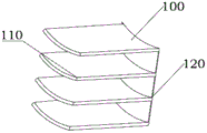
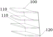
FIG. 4 is one of the structures of the flow guiding grids of the embodiment of the present invention;
FIG. 5 is one of the structures of the flow-guiding grille of the embodiment of the present invention;
FIG. 6 is one of the structures of the flow guiding grids of the embodiment of the present invention;
reference numerals:
100. a flow-guiding grille; 110. a guide vane; 120. a vertical plate; 121. a protrusion;
200. an air outlet;
300. a housing.
Detailed Description
The following detailed description of the embodiments of the present invention is provided with reference to the accompanying drawings and examples. The following examples are intended to illustrate the invention, but are not intended to limit the scope of the invention.
In the description of the present application, it is to be understood that the terms "center", "upper", "lower", "front", "rear", "left", "right", "vertical", "horizontal", "top", "bottom", "inner", "outer", and the like indicate orientations or positional relationships based on those shown in the drawings, and are only for convenience in describing the present application and simplifying the description, but do not indicate or imply that the referred device or element must have a particular orientation, be constructed in a particular orientation, and be operated, and thus should not be construed as limiting the present application.
The terms "first", "second" and "first" are used for descriptive purposes only and are not to be construed as indicating or implying relative importance or implicitly indicating the number of technical features indicated. Thus, a feature defined as "first" or "second" may explicitly or implicitly include one or more of that feature. In the description of the present application, "a plurality" means two or more unless otherwise specified.
In the description of the present application, it is to be noted that, unless otherwise explicitly specified or limited, the terms "mounted," "connected," and "connected" are to be construed broadly, e.g., as meaning either a fixed connection, a removable connection, or an integral connection; can be mechanically or electrically connected; they may be connected directly or indirectly through intervening media, or they may be interconnected between two elements. The specific meaning of the above terms in the present application can be understood in a specific case by those of ordinary skill in the art.
The indoor unit of an air conditioner performs a refrigeration cycle of the indoor unit of an air conditioner by using a compressor, a condenser, an expansion valve, and an evaporator. The refrigeration cycle includes a series of processes involving compression, condensation, expansion, and evaporation, and supplies refrigerant to the air that has been conditioned and heat-exchanged.
The compressor compresses a refrigerant gas in a high-temperature and high-pressure state and discharges the compressed refrigerant gas. The discharged refrigerant gas flows into the condenser. The condenser condenses the compressed refrigerant into a liquid phase, and heat is released to the surrounding environment through the condensation process.
The expansion valve expands the liquid-phase refrigerant in a high-temperature and high-pressure state condensed in the condenser into a low-pressure liquid-phase refrigerant. The evaporator evaporates the refrigerant expanded in the expansion valve and returns the refrigerant gas in a low-temperature and low-pressure state to the compressor. The evaporator can achieve a cooling effect by heat-exchanging with a material to be cooled using latent heat of evaporation of a refrigerant. The air conditioning indoor unit can adjust the temperature of the indoor space throughout the cycle.
The outdoor unit of the air conditioning indoor unit refers to a portion of the refrigeration cycle including the compressor and the outdoor heat exchanger, the indoor unit of the air conditioning indoor unit includes the indoor heat exchanger, and the expansion valve may be provided in the indoor unit or the outdoor unit.
The indoor heat exchanger and the outdoor heat exchanger serve as a condenser or an evaporator. When the indoor heat exchanger is used as a condenser, the indoor air conditioner serves as a heater in a heating mode, and when the indoor heat exchanger is used as an evaporator, the indoor air conditioner serves as a cooler in a cooling mode.
An air conditioning indoor unit according to some embodiments of the present application includes an indoor unit installed in an indoor space. And an indoor unit connected to an outdoor unit (not shown) installed in the outdoor space through a pipe. The outdoor unit may be provided therein with a compressor, an outdoor heat exchanger, an outdoor fan, an expander, and the like of a refrigeration cycle, and the indoor unit may be provided therein with an indoor heat exchanger and an indoor fan.
For example, the indoor unit may include a wall-mounted indoor unit installed on a wall of the indoor space.
An indoor unit includes a case 300, and a plurality of components constituting a refrigeration cycle are mounted in the case 300. The case 300 includes a front surface that is at least partially opened, a rear surface that is mounted on a wall of the indoor space and provided with a mounting plate, a bottom surface defining a bottom configuration, side surfaces provided at both sides of the bottom surface, and a top surface defining a top appearance.
A front panel is provided at a front of the open portion of the front surface, the front panel defining a front appearance of the indoor unit.
The mounting plate is coupled to the rear surface. The mounting plate may define a mounting hole therein that is coupled to the wall. For example, a mounting plate may be coupled to the wall, and the housing 300 may be configured to mount on the mounting plate.
The casing 300 may be an indoor unit casing 300 provided in an indoor space in the case of a split type air conditioner, or may be an air conditioner own casing 300 in the case of an integrated type air conditioner. Also, the front panel may be understood as one component of the case 300 in a broad sense.
A fan is installed in the housing 300. For example, the fan may include a cross flow fan that radially discharges air drawn in a circumferential direction.
The fan may have a shape of a plurality of blades arranged in a circumferential direction. Also, the fan extends in the left-right direction in the case 300. Here, the axial direction of the fan may be a left-right direction.
The fan motor is coupled to one side of the fan. The fan motor is driven to provide a rotational force to the fan. Also, the other side of the fan may be supported inside the case 300.
Referring to fig. 1 to 3, in the refrigeration anti-blow-through mode, the guide grid 100 starts to rotate, guides the cold airflow upwards by a larger angle, and realizes wind sheltering, and the guide vanes 110 perform multi-stage flow guiding to finish wind outlet.
In the heating mode, the structure of the guide grid 100 can start to rotate, the hot air flow is guided downwards at a larger angle, negative-angle air outlet is realized, and meanwhile, the guide vanes 110 perform multi-stage guide to form carpet air, so that the optimal heating effect is realized, and air outlet is completed.
Referring to fig. 4 to 6, the flow-guiding grille 100 further includes guide vanes 110 and a vertical plate 120, the vertical plate 120 is connected to both sides of the air outlet 200, the guide vanes 110 are connected to the vertical plate 120, the guide vanes 110 have a length of 10mm to 15mm and a thickness of 1mm, the vertical plate 120 further includes protrusions 121, the protrusions 121 are disposed on the inner side of the vertical plate 120, the protrusions 121 are connected to the side walls of the air outlet 200 in a snap-fit manner, the number of the guide vanes 110 is four or more, and the four or more guide vanes 110 are vertically connected to the inner side of the; the number of the guide grids 100 is two or more, the two or more guide grids 100 are sequentially detachably connected in the air outlet 200, the four or more guide vanes 110 are arc-shaped structures, and the four or more guide vanes 110 can also be straight-plate-shaped structures or the combination of the straight-plate-shaped structures and the arc-shaped structures.
Referring to fig. 1 to 6, when installing the guide grids 100, it is only necessary to sequentially connect a plurality of guide grids 100, and connect the protrusions 121 at both ends thereof to the sidewalls of the air outlet 200 in a snap-fit manner, thereby completing the installation.
When the grille 100 is disassembled, the protrusions 121 at the two ends of the grille 100 are only required to be separated from the side wall of the air outlet 200, so that the disassembly can be completed.
According to the first concept of the present application, since the flow guide grille of the present application can rotate 360 degrees, a large-angle upward or downward flow guide can be realized, and an optimal cooling or heating effect can be realized.
According to the second concept of the application, because the air guide grids are two or more, the 360-degree air guide of the on-hook air outlet in the partition area difference can be realized, and the diversified comfort requirements of users are met.
According to the third concept of the invention, the four or more guide vanes are provided, the length of the guide vanes is 10-15 mm, and the thickness of the guide vanes is 1mm, so that the wind resistance is smaller than that of the traditional single air guide plate, the influence on the attenuation of the air volume during heating or heating is small, more air supply capacity of the on-hook is reserved, and the performance is improved.
The above is only a preferred embodiment of the present invention, and it should be noted that, for those skilled in the art, a plurality of modifications and substitutions can be made without departing from the technical principle of the present invention, and these modifications and substitutions should also be regarded as the protection scope of the present invention.
Claims (7)
1. An indoor unit of an air conditioner, comprising:
a housing mounted to a wall of an indoor space, and provided with a heat exchanger and a fan therein;
the air outlet is formed in the shell;
the flow guide grating is rotatably arranged at the air outlet;
wherein, the water conservancy diversion grid includes:
the vertical plates are connected to two sides of the air outlet;
the guide vane is connected to the vertical plate;
the protrusion is arranged on the outer side of the vertical plate and connected to the side wall of the air outlet in a clamping mode.
2. An indoor unit of an air conditioner according to claim 1, wherein the guide vane has a length of 10mm to 15mm and a thickness of 1 mm.
3. The indoor unit of claim 2, wherein the number of the guide vanes is four or more, and four or more guide vanes are vertically connected to the inner sides of the vertical plates.
4. An indoor unit of an air conditioner according to claim 3, wherein the distances between four or more guide vanes are the same.
5. An indoor unit of an air conditioner according to claim 3, wherein distances between four or more of the guide vanes are different.
6. The indoor unit of claim 5, wherein four or more guide vanes have a circular arc shape.
7. The indoor unit of claim 1, wherein the number of the guide grilles is two or more, and the two or more guide grilles are detachably connected to the outlet in sequence.
Priority Applications (1)
| Application Number | Priority Date | Filing Date | Title |
|---|---|---|---|
| CN202020825233.6U CN213272829U (en) | 2020-05-18 | 2020-05-18 | Air conditioner indoor unit |
Applications Claiming Priority (1)
| Application Number | Priority Date | Filing Date | Title |
|---|---|---|---|
| CN202020825233.6U CN213272829U (en) | 2020-05-18 | 2020-05-18 | Air conditioner indoor unit |
Publications (1)
| Publication Number | Publication Date |
|---|---|
| CN213272829U true CN213272829U (en) | 2021-05-25 |
Family
ID=75936136
Family Applications (1)
| Application Number | Title | Priority Date | Filing Date |
|---|---|---|---|
| CN202020825233.6U Active CN213272829U (en) | 2020-05-18 | 2020-05-18 | Air conditioner indoor unit |
Country Status (1)
| Country | Link |
|---|---|
| CN (1) | CN213272829U (en) |
Cited By (1)
| Publication number | Priority date | Publication date | Assignee | Title |
|---|---|---|---|---|
| CN113819519A (en) * | 2021-08-31 | 2021-12-21 | 青岛海尔空调器有限总公司 | Air supply structure and air conditioner |
-
2020
- 2020-05-18 CN CN202020825233.6U patent/CN213272829U/en active Active
Cited By (1)
| Publication number | Priority date | Publication date | Assignee | Title |
|---|---|---|---|---|
| CN113819519A (en) * | 2021-08-31 | 2021-12-21 | 青岛海尔空调器有限总公司 | Air supply structure and air conditioner |
Similar Documents
| Publication | Publication Date | Title |
|---|---|---|
| CN214949402U (en) | Indoor machine of air conditioner | |
| CN213272829U (en) | Air conditioner indoor unit | |
| CN215062438U (en) | Indoor machine of air conditioner | |
| CN215001918U (en) | Indoor machine of air conditioner | |
| CN215001915U (en) | Indoor machine of air conditioner | |
| CN215001919U (en) | Indoor machine of air conditioner | |
| CN215808848U (en) | Indoor machine of air conditioner | |
| CN216424007U (en) | Parking air conditioner | |
| CN219913370U (en) | Hanging air conditioner | |
| CN219889754U (en) | Hanging air conditioner | |
| CN216924535U (en) | Indoor air conditioner | |
| CN215570831U (en) | Indoor air conditioner | |
| CN218154479U (en) | Indoor unit of air conditioner | |
| CN217082721U (en) | Indoor unit of air conditioner | |
| CN213395594U (en) | Air conditioner | |
| CN217635914U (en) | Indoor unit of air conditioner | |
| CN215808849U (en) | Indoor machine of air conditioner | |
| CN212673371U (en) | Air conditioner | |
| CN218379620U (en) | Indoor unit of air conditioner | |
| CN217109774U (en) | Indoor unit of air conditioner | |
| CN217357466U (en) | Indoor air conditioner | |
| CN217876140U (en) | Indoor unit of air conditioner | |
| CN217109787U (en) | Indoor unit of air conditioner | |
| CN218846291U (en) | Indoor unit of air conditioner | |
| CN217109776U (en) | Indoor unit of air conditioner |
Legal Events
| Date | Code | Title | Description |
|---|---|---|---|
| GR01 | Patent grant | ||
| GR01 | Patent grant | ||
| CP03 | Change of name, title or address |
Address after: No.1 Haixin Road, Nancun Town, Pingdu City, Qingdao City, Shandong Province Patentee after: Hisense Air Conditioning Co.,Ltd. Country or region after: China Address before: No. 151, Zhuzhou Road, Laoshan District, Qingdao, Shandong Patentee before: HISENSE (SHANDONG) AIR-CONDITIONING Co.,Ltd. Country or region before: China |