CN211817946U - Template structure of cast-in-place bare concrete wall - Google Patents
Template structure of cast-in-place bare concrete wall Download PDFInfo
- Publication number
- CN211817946U CN211817946U CN201921323726.3U CN201921323726U CN211817946U CN 211817946 U CN211817946 U CN 211817946U CN 201921323726 U CN201921323726 U CN 201921323726U CN 211817946 U CN211817946 U CN 211817946U
- Authority
- CN
- China
- Prior art keywords
- template
- template panel
- concrete
- vertical
- positioning
- Prior art date
- Legal status (The legal status is an assumption and is not a legal conclusion. Google has not performed a legal analysis and makes no representation as to the accuracy of the status listed.)
- Active
Links
- 239000004567 concrete Substances 0.000 title claims abstract description 75
- XLYOFNOQVPJJNP-UHFFFAOYSA-N water Substances O XLYOFNOQVPJJNP-UHFFFAOYSA-N 0.000 claims abstract description 13
- 238000009415 formwork Methods 0.000 claims description 31
- 229910000831 Steel Inorganic materials 0.000 claims description 22
- 239000010959 steel Substances 0.000 claims description 22
- 230000002787 reinforcement Effects 0.000 claims description 13
- 238000000034 method Methods 0.000 claims description 8
- 230000000149 penetrating effect Effects 0.000 claims description 6
- 238000010276 construction Methods 0.000 abstract description 10
- 238000003780 insertion Methods 0.000 description 9
- 230000037431 insertion Effects 0.000 description 9
- 238000010586 diagram Methods 0.000 description 8
- 239000010410 layer Substances 0.000 description 3
- XEEYBQQBJWHFJM-UHFFFAOYSA-N Iron Chemical compound [Fe] XEEYBQQBJWHFJM-UHFFFAOYSA-N 0.000 description 2
- 238000003825 pressing Methods 0.000 description 2
- 206010063659 Aversion Diseases 0.000 description 1
- 230000009286 beneficial effect Effects 0.000 description 1
- 239000011248 coating agent Substances 0.000 description 1
- 238000000576 coating method Methods 0.000 description 1
- 230000000694 effects Effects 0.000 description 1
- 229910052742 iron Inorganic materials 0.000 description 1
- 238000004519 manufacturing process Methods 0.000 description 1
- 239000000463 material Substances 0.000 description 1
- 239000004540 pour-on Substances 0.000 description 1
- 239000011241 protective layer Substances 0.000 description 1
- 230000003014 reinforcing effect Effects 0.000 description 1
- 239000011376 self-consolidating concrete Substances 0.000 description 1
- 239000004575 stone Substances 0.000 description 1
- -1 tile pasting Substances 0.000 description 1
- 239000002023 wood Substances 0.000 description 1
Images


Landscapes
- Forms Removed On Construction Sites Or Auxiliary Members Thereof (AREA)
Abstract
A template structure of a cast-in-place bare concrete wall comprises a template panel, a vertical back ridge, a transverse back ridge and a water stop bolt; a concrete guide wall is arranged at the bottom of the bare concrete wall body; the template panel is arranged on the concrete guide wall; inserting rods are respectively arranged on the top surface of the concrete guide wall along the transverse edges of the two sides, and a group of inserting rods is arranged at intervals along the transverse edge of each side; the bottom surface of the template panel is provided with jacks; the template panel is connected with the concrete guide wall in an inserting way; a group of positioning pieces are arranged at the top of the template panel; the positioning piece comprises a positioning plate and a positioning block; the positioning plate is erected between the tops of the two side template panels; the two positioning blocks are connected to the bottom of the positioning plate at intervals along the longitudinal direction and are in surface contact with the inner side surfaces of the two template panels respectively. The utility model provides an among the current clear water concrete work progress of watering to the difficult, template structure construction difficulty of accuse of each part, easily rise mould and clear water concrete's quality and can not obtain the technical problem of assurance.
Description
Technical Field
The utility model belongs to the building engineering construction field, especially a cast-in-place clear water concrete wall's template structure.
Background
The fair-faced concrete refers to a method for representing a plain color of concrete without any materials such as coating, tile pasting, stone pasting and the like after concrete pouring, and is also called as decorative concrete due to the extremely good decorative effect; since the bare concrete is no longer decorated, it must be managed with great care during the construction phase. The existing fair-faced concrete is divided into a prefabricated type and a cast-in-place type, wherein the prefabricated type fair-faced concrete has certain guarantee on engineering quality because the prefabricated type fair-faced concrete is processed in a factory, the cast-in-place type fair-faced concrete is rarely used in general buildings, in the construction process of the cast-in-place fair-faced concrete, the control of each part is difficult, the construction of a template structure of a wall body is difficult, a mold is easy to expand in the pouring process, and the quality of the constructed fair-faced concrete cannot be guaranteed.
SUMMERY OF THE UTILITY MODEL
The utility model aims at providing a cast-in-place clear water concrete wall's template structure, the technical problem that the clear water concrete quality that will solve among the current clear water concrete work progress of watering to the more difficult, the template structure construction of wall body of accuse of each part is more difficult, pour the in-process and rise the mould easily and the construction finishes can not obtain the assurance.
In order to achieve the above purpose, the utility model adopts the following technical scheme.
A template structure of a cast-in-place bare concrete wall comprises template panels arranged on the front side and the rear side of the bare concrete wall to be poured, vertical back ridges arranged on the outer sides of the template panels in a pressing mode, transverse back ridges arranged on the outer sides of the vertical back ridges and water stop bolts tied between the transverse back ridges on the two sides; a concrete guide wall is arranged at the bottom of the bare concrete wall to be cast; the formwork panel is arranged on the concrete guide wall; vertical inserting rods are respectively arranged on the top surface of the concrete guide wall along the transverse edges of the two sides, and a group of inserting rods are arranged at intervals along the transverse edge of each side; vertical jacks are arranged on the bottom surface of the template panel and at positions corresponding to the inserted rods; the template panel is connected with the concrete guide wall in an inserting manner; a group of positioning pieces are transversely arranged on the top of the template panel at intervals in parallel; wherein each positioning piece comprises a positioning plate and a positioning block; the positioning plate is longitudinally erected between the tops of the two side template panels; the two positioning blocks are connected to the bottom of the positioning plate at intervals along the longitudinal direction and are in surface contact with the inner side surfaces of the two template panels respectively.
Preferably, the template panel is formed by splicing a group of template panel units.
Preferably, vertical connecting rods are respectively arranged on the outer surface of the template panel unit and along the vertical edges at the two sides; through holes are arranged on the transverse side surface of the vertical connecting rod at intervals along the vertical direction; the vertical connecting rod is connected to the template panel unit through a fastener penetrating through the through hole; connecting holes are formed in the longitudinal side face of the vertical connecting rod at intervals along the vertical direction; two transversely adjacent template panel units are connected through a first bolt which is arranged in a connecting hole in the adjacent vertical connecting rod in a penetrating manner.
Preferably, two vertically adjacent template panel units are connected in an inserting manner; the top of the template panel unit on the lower layer is provided with a top surface insert block and a top slot, the bottom of the template panel unit on the upper layer is provided with a bottom insert block and a bottom slot, the bottom insert block corresponds to the top slot, and the bottom slot corresponds to the top surface insert block.
Preferably, a group of connecting blocks are arranged outside the splicing seams of two vertically adjacent template panel units at intervals along the transverse direction; the upper end of connecting block can be dismantled with the template panel unit on upper strata and be connected, the lower upper end of connecting block can be dismantled with the template panel unit of lower floor and be connected.
Preferably, the lower end of the steel reinforcement framework of the bare concrete wall body is embedded in the concrete guide wall; snap rings are respectively arranged on the front side and the rear side of the steel bar framework at intervals; the clamping ring on the front side surface of the steel bar framework is contacted with the template panel on the front side, and the clamping ring on the rear side surface of the steel bar framework is contacted with the template panel on the rear side.
Compared with the prior art, the utility model has the following characteristics and beneficial effect.
1. In the utility model, two vertically adjacent template panel units are connected in an inserting way; meanwhile, the utility model is provided with a group of connecting blocks outside the splicing seam of two vertically adjacent template panel units and along the transverse interval, and the vertically adjacent template panel units are fixed through the connecting blocks; the utility model firstly carries out preliminary fixing on two vertically adjacent template panel units through the splicing connection, and then carries out final fixing through the connecting block; the connecting mode has the advantages of simple construction and firm connection, and avoids the condition of mold expansion in the process of pouring concrete.
2. The utility model is provided with vertical connecting rods on the outer surface of the template panel unit and along the vertical edges at two sides, and the template panel units at two sides of the joint are tied by a first bolt between two adjacent template panel units; the connecting mode has the advantages of simple construction and firm connection, and avoids the condition of mold expansion in the process of pouring concrete.
3. The utility model is provided with vertical inserted bars on the top surface of the concrete guide wall and along the transverse edges of the two sides, and the template panels on the two sides are respectively inserted on the inserted bars; meanwhile, the utility model arranges a positioning piece on the top of the template panel; through fixing a position top and bottom to the template panel, prevented to pour the in-process template panel and produced the aversion, influenced the quality of pouring of fair-faced concrete.
4. The utility model discloses set up the stopper at the top of template panel, the position department that is located the setting element both sides, the effectual slip that prevents the locating part.
Drawings
The present invention will be described in further detail with reference to the accompanying drawings.
Fig. 1 is the structure schematic diagram of the utility model discloses well clear water concrete wall body is pour on the concrete guide wall.
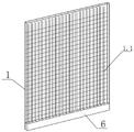
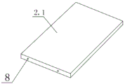
Fig. 2 is a schematic structural diagram of the middle formwork panel of the present invention.
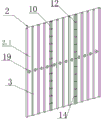
Fig. 3 is a schematic structural diagram of the connection of the adjacent formwork panel units in the present invention.
Fig. 4 is the utility model discloses well adjacent template panel unit splice seam department's node structure schematic diagram.
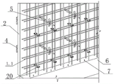
Fig. 5 is the schematic view of the inner side structure of the middle formwork panel of the present invention supported on the concrete guide wall.
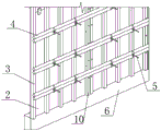
Fig. 6 is the outer side structure diagram of the middle formwork panel of the utility model supported on the concrete guide wall.
Fig. 7 is a schematic structural diagram of the middle form panel unit of the present invention with top surface insert blocks and top slots.
Fig. 8 is a schematic structural diagram of the middle form panel unit of the present invention with a bottom insert block and a bottom slot.
Fig. 9 is a schematic structural view of the lowermost formwork panel unit in the present invention.
Fig. 10 is a schematic structural view of the positioning member disposed on the top of the middle formwork panel of the present invention.
Fig. 11 is a schematic structural diagram of a positioning member of the present invention.
Reference numerals: the concrete wall comprises a 1-fair-faced concrete wall body, a 1.1-steel reinforcement framework, a 2-formwork panel, a 2.1-formwork panel unit, a 3-vertical back ridge, a 4-horizontal back ridge, a 5-water stop bolt, a 6-concrete guide wall, a 7-inserted rod, an 8-jack, a 9-positioning piece, a 9.1-positioning plate, a 9.2-positioning piece, a 10-vertical connecting rod, an 11-perforation, a 12-fastening piece, a 13-connecting hole, a 14-first bolt, a 15-top surface inserted block, a 16-top slot, a 17-bottom inserted block, a 18-bottom slot, a 19-connecting block, a 20-snap ring and a 21-limiting block.
Detailed Description
As shown in fig. 1-11, the formwork structure of the cast-in-place bare concrete wall comprises formwork panels 2 arranged on the front side and the rear side of a bare concrete wall 1 to be poured, vertical back ridges 3 arranged on the outer sides of the formwork panels 2 in a pressing manner, transverse back ridges 4 arranged on the outer sides of the vertical back ridges 3, and water stop bolts 5 tied between the transverse back ridges 4 on the two sides; a concrete guide wall 6 is arranged at the bottom of the bare concrete wall 1 to be cast; the template panel 2 is arranged on the concrete guide wall 6; vertical insertion rods 7 are respectively arranged on the top surface of the concrete guide wall 6 along the transverse edges of the two sides, and a group of insertion rods 7 are arranged at intervals along the transverse edge of each side; a vertical jack 8 is arranged at the bottom surface of the template panel 2 and at the position corresponding to the inserted rod 7; the template panel 2 is connected with the concrete guide wall 6 in an inserting manner; a group of positioning pieces 9 are transversely arranged on the top of the template panel 2 at intervals in parallel; wherein, each positioning part 9 comprises a positioning plate 9.1 and a positioning block 9.2; the positioning plate 9.1 is longitudinally erected between the tops of the two side template panels 2; the two positioning blocks 9.2 are connected to the bottom of the positioning plate 9.1 at intervals along the longitudinal direction, and the two positioning blocks 9.2 are in surface contact with the inner side surfaces of the two template panels 2 respectively.
In this embodiment, the template panel 2 is formed by splicing a group of template panel units 2.1.
In this embodiment, vertical connecting rods 10 are respectively arranged on the outer surface of the template panel unit 2.1 along the vertical edges at the two sides; through holes 11 are arranged on the transverse side surface of the vertical connecting rod 10 at intervals along the vertical direction; the vertical connecting rod 10 is connected to the template panel unit 2.1 through a fastener 12 arranged in the through hole 11 in a penetrating way; connecting holes 13 are formed in the longitudinal side face of the vertical connecting rod 10 at intervals along the vertical direction; two transversely adjacent template panel units 2.1 are connected through first bolts 14 which are arranged in connecting holes 13 on adjacent vertical connecting rods 10 in a penetrating manner.
In the embodiment, two vertically adjacent template panel units 2.1 are connected in an inserting manner; wherein, the top of the template panel unit 2.1 of lower floor is provided with top surface inserted block 15 and top slot 16, and the bottom of the template panel unit 2.1 of upper floor is provided with bottom inserted block 17 and bottom slot 18 to bottom inserted block 17 corresponds the setting with top slot 16, and bottom slot 18 corresponds the setting with top surface inserted block 15.
In this embodiment, the insertion holes 8 are formed in the bottom of the lowermost formwork panel unit 2.1, the bottom of the lowermost formwork panel unit 2.1 is not provided with the bottom insertion blocks 17 and the bottom insertion slots 18, and the top insertion blocks 15 and the top insertion slots 16 on the top of the lowermost formwork panel unit 2.1 are used for connecting the bottom insertion blocks 17 and the bottom insertion slots 18 at the bottom of the next lower formwork panel unit 2.1; the top of the template panel unit 2.1 at the uppermost layer is not provided with a top surface insert block 15 and a top slot 16, and only a limiting block 21 is arranged; the limiting blocks 21 are arranged on two sides of each positioning plate 9.1 to prevent the positioning plates 9.1 from sliding; a bottom insert block 17 and a bottom insert groove 18 are arranged at the bottom of the uppermost formwork panel unit 2.1 for connecting the top insert block 15 and the top insert groove 16 at the top of the next uppermost formwork panel unit 2.1.
In the embodiment, a group of connecting blocks 19 are arranged outside the splicing seam of two vertically adjacent template panel units 2.1 at intervals along the transverse direction; the upper end of connecting block 19 can be dismantled with the template panel unit 2.1 on upper strata and be connected, the lower upper end of connecting block 19 can be dismantled with the template panel unit 2.1 on lower floor and be connected.
In this embodiment, the connecting blocks 19 are made of wood blocks, and the distance between the adjacent connecting blocks 19 in the transverse direction is not more than 250 mm.
Of course, in other embodiments, the connecting block 19 may also be made of iron sheet or steel sheet.
In this embodiment, the lower end of the steel reinforcement framework 1.1 of the bare concrete wall 1 is embedded in the concrete guide wall 6; snap rings 20 are respectively arranged on the front side and the rear side of the steel reinforcement framework 1.1 at intervals; wherein, snap ring 20 on the framework of steel reinforcement 1.1 leading flank contacts with the template panel 2 of front side, and snap ring 20 on the framework of steel reinforcement 1.1 trailing flank contacts with the template panel 2 of rear side.
In this embodiment, the template panel unit 2.1 is made of a high-quality film-coated multilayer board, and the thickness of the template panel unit 2.1 is 10mm to 20 mm.
In this embodiment, the fastening members 12 are bolts, and the distance between adjacent fastening members 12 is 20cm to 40 cm.
In the embodiment, the distance between the adjacent vertical back ridges 3 is 25 cm-40 cm.
Of course, in other embodiments, the fastener 12 may also be a screw or a steel nail.
In this embodiment, the construction method of the formwork structure of the cast-in-place bare concrete wall includes the following steps.
Step one, constructing a concrete guide wall 6 at the bottom: according to the wall thickness of the fair-faced concrete wall 1, a concrete guide wall 6 at the bottom is firstly constructed, and the concrete guide wall is provided with a steel reinforcement framework 1.1 used by the fair-faced concrete wall 1.
And step two, prefabricating the formwork panel 2 on one side, wherein the formwork panel 2 is formed by splicing formwork panel units 2.1 made of high-quality film-coated multilayer plates closely, connecting the upper formwork panel unit 2.1 with the lower formwork panel unit 2.1 by using a connecting block 19, and connecting the left formwork panel unit 2.1 with the right formwork panel unit 2.1 by using a vertical connecting rod 10 and a first bolt 14.
And step three, after the connecting blocks 19 are fixed, connecting the vertical back edges 3 on the outer side of the template panel 2.
After the vertical back edges 3 of the templates are fixed, hoisting the single-side template to a specified position by using a crane, and installing a plastic snap ring 20 to ensure the minimum distance between the steel reinforcement framework 1.1 and the template panel 2 and the thickness of the concrete protective layer; the vertical direction interval of snap ring 20 is 500mm, and the horizontal direction interval is two reinforcing bars.
Step five, then open the hole that passes stagnant water bolt 5 on template panel 2, the hole is 500mm in vertical and horizontal direction equal interval, if touching framework of steel reinforcement 1.1 simultaneously, then move 5cm trompil downwards in order to avoid framework of steel reinforcement 1.1 on the basis of original position.
And sixthly, mounting the transverse back edge 4 after the clamping ring 20 and the water-stopping bolt 5 are completely mounted, wherein the transverse back edge 4 adopts double rows of circular steel tubes with the outer diameter of 48mm and the thickness of 3mm, and the upper and lower intervals of the double rows of circular steel tubes are 450mm and the double rows of circular steel tubes are firmly mounted with the water-stopping bolt 5.
And step seven, finally, closing the die, keeping the manufacturing process of the template on the other side unchanged, hoisting the template on the side of the other side to a specified position by using a crane, installing a positioning piece 9, opening a hole, and connecting the transverse back edges 4 on the two sides.
And step eight, pouring by using self-compacting concrete after the template structure is installed.
The above embodiments are not exhaustive of the specific embodiments, and other embodiments are possible, and the above embodiments are intended to illustrate, but not limit the scope of the present invention, and all applications coming from the simple changes of the present invention fall within the scope of the present invention.
Claims (6)
1. A template structure of a cast-in-place bare concrete wall comprises template panels (2) arranged on the front side and the rear side of a bare concrete wall (1) to be poured, vertical back ridges (3) pressed on the outer sides of the template panels (2), transverse back ridges (4) arranged on the outer sides of the vertical back ridges (3) and water stop bolts (5) tied between the transverse back ridges (4) on the two sides; the method is characterized in that: a concrete guide wall (6) is arranged at the bottom of the bare concrete wall (1) to be cast; the template panel (2) is arranged on the concrete guide wall (6); vertical inserted rods (7) are respectively arranged on the top surface of the concrete guide wall (6) along the transverse edges of the two sides, and a group of inserted rods (7) are arranged at intervals along the transverse edge of each side; a vertical jack (8) is arranged on the bottom surface of the template panel (2) and at a position corresponding to the inserted rod (7); the template panel (2) is connected with the concrete guide wall (6) in an inserting manner; a group of positioning pieces (9) are arranged on the top of the template panel (2) in parallel at intervals along the transverse direction; wherein each positioning piece (9) comprises a positioning plate (9.1) and a positioning block (9.2); the positioning plate (9.1) is longitudinally erected between the tops of the two side template panels (2); the two positioning blocks (9.2) are connected to the bottom of the positioning plate (9.1) at intervals along the longitudinal direction, and the two positioning blocks (9.2) are in surface contact with the inner side surfaces of the two template panels (2) respectively.
2. The formwork structure of a cast-in-place bare concrete wall according to claim 1, characterized in that: the template panel (2) is formed by splicing a group of template panel units (2.1).
3. The formwork structure of a cast-in-place bare concrete wall according to claim 2, characterized in that: vertical connecting rods (10) are respectively arranged on the outer surface of the template panel unit (2.1) along the vertical edges at the two sides; through holes (11) are arranged on the transverse side surface of the vertical connecting rod (10) at intervals along the vertical direction; the vertical connecting rod (10) is connected to the template panel unit (2.1) through a fastener (12) arranged in the through hole (11) in a penetrating mode; connecting holes (13) are arranged on the longitudinal side surface of the vertical connecting rod (10) at intervals along the vertical direction; two transversely adjacent template panel units (2.1) are connected through a first bolt (14) arranged in a connecting hole (13) on the adjacent vertical connecting rod (10) in a penetrating manner.
4. The formwork structure of a cast-in-place bare concrete wall according to claim 2, characterized in that: two vertically adjacent template panel units (2.1) are connected in an inserting way; wherein, the top of the template panel unit (2.1) of lower floor is provided with top surface inserted block (15) and top slot (16), and the bottom of the template panel unit (2.1) of upper strata is provided with bottom inserted block (17) and bottom slot (18) to bottom inserted block (17) corresponds the setting with top slot (16), and bottom slot (18) correspond the setting with top surface inserted block (15).
5. The formwork structure of a cast-in-place bare concrete wall according to claim 2, characterized in that: a group of connecting blocks (19) are arranged outside the splicing seam of two vertically adjacent template panel units (2.1) at intervals along the transverse direction; the upper end of connecting block (19) can be dismantled with the template panel unit (2.1) on upper strata and be connected, the lower upper end of connecting block (19) can be dismantled with the template panel unit (2.1) on lower floor and be connected.
6. The formwork structure of a cast-in-place bare concrete wall according to claim 3, characterized in that: the lower end of a steel reinforcement framework (1.1) of the bare concrete wall body (1) is embedded in the concrete guide wall (6); snap rings (20) are respectively arranged on the front side and the rear side of the steel bar framework (1.1) at intervals; wherein, snap ring (20) on the framework of steel reinforcement (1.1) leading flank contacts with template panel (2) of front side, snap ring (20) on the framework of steel reinforcement (1.1) trailing flank contacts with template panel (2) of rear side.
Priority Applications (1)
| Application Number | Priority Date | Filing Date | Title |
|---|---|---|---|
| CN201921323726.3U CN211817946U (en) | 2019-08-15 | 2019-08-15 | Template structure of cast-in-place bare concrete wall |
Applications Claiming Priority (1)
| Application Number | Priority Date | Filing Date | Title |
|---|---|---|---|
| CN201921323726.3U CN211817946U (en) | 2019-08-15 | 2019-08-15 | Template structure of cast-in-place bare concrete wall |
Publications (1)
| Publication Number | Publication Date |
|---|---|
| CN211817946U true CN211817946U (en) | 2020-10-30 |
Family
ID=72994587
Family Applications (1)
| Application Number | Title | Priority Date | Filing Date |
|---|---|---|---|
| CN201921323726.3U Active CN211817946U (en) | 2019-08-15 | 2019-08-15 | Template structure of cast-in-place bare concrete wall |
Country Status (1)
| Country | Link |
|---|---|
| CN (1) | CN211817946U (en) |
Cited By (2)
| Publication number | Priority date | Publication date | Assignee | Title |
|---|---|---|---|---|
| CN113898170A (en) * | 2021-11-15 | 2022-01-07 | 贵州建工集团第一建筑工程有限责任公司 | Supporting template with interfaces capable of being embedded into each other |
| CN114197704A (en) * | 2021-12-23 | 2022-03-18 | 江苏精享裕建工有限公司 | Converter station firewall construction process |
-
2019
- 2019-08-15 CN CN201921323726.3U patent/CN211817946U/en active Active
Cited By (2)
| Publication number | Priority date | Publication date | Assignee | Title |
|---|---|---|---|---|
| CN113898170A (en) * | 2021-11-15 | 2022-01-07 | 贵州建工集团第一建筑工程有限责任公司 | Supporting template with interfaces capable of being embedded into each other |
| CN114197704A (en) * | 2021-12-23 | 2022-03-18 | 江苏精享裕建工有限公司 | Converter station firewall construction process |
Similar Documents
| Publication | Publication Date | Title |
|---|---|---|
| US10837166B2 (en) | Building structure and construction method for same | |
| CN103195087B (en) | Mould support method of foundation pit basement haunch shearing wall | |
| CN111946050A (en) | Aluminum alloy formwork construction method applied to assembly type engineering | |
| CN211817946U (en) | Template structure of cast-in-place bare concrete wall | |
| CN110067321B (en) | Flexible connecting device for assembled shear wall and construction method thereof | |
| CN216920791U (en) | T-shaped shear wall assembly and building structure | |
| CN219863375U (en) | Constructional column top reinforcing steel bar pre-burying device | |
| CN211817040U (en) | Slurry leakage prevention structure at splicing part of assembled laminated slab | |
| CN210263490U (en) | Assembled wall that possesses adjustable extending structure | |
| CN211472963U (en) | Connecting structure of cast-in-situ hidden column and prefabricated part | |
| CN109296117B (en) | Composite hollow inner template light partition wall and construction method | |
| CN217379518U (en) | Constructional column and horizontal tie beam formwork-free construction component | |
| CN207419752U (en) | Can assemble anti-bank of precast concrete | |
| CN115749043A (en) | Assembled building wallboard connected node structure | |
| CN112663788B (en) | Assembled rapid construction method | |
| CN216552513U (en) | Fabricated batten wall constructional column prefabricated part based on straight tenon | |
| CN211447004U (en) | Reinforced GRC plate and pipe ditch foundation formwork system combining same | |
| CN209990139U (en) | Structure is assembled to constructional column template | |
| CN210288864U (en) | Assembled prefabricated wall board | |
| KR20220010301A (en) | Deck panel for Euroform | |
| CN206220482U (en) | A kind of cast-in-situ wall template support system | |
| CN112302332A (en) | Template for single-side formwork support of color decorative rammed earth background wall and construction method thereof | |
| CN212104672U (en) | Plastering structure at node of sandwich heat-insulation double-sided superposed shear wall and out-of-band heat-insulation bay window | |
| CN110725441A (en) | Steel concrete casting structure of large wood-wool cement wallboard and building frame structure of fabricated building | |
| CN216810401U (en) | Concrete prefabricated wall body component and template for prefabricating same |
Legal Events
| Date | Code | Title | Description |
|---|---|---|---|
| GR01 | Patent grant | ||
| GR01 | Patent grant |