CN211814655U - Improved generation acidizing pond - Google Patents
Improved generation acidizing pond Download PDFInfo
- Publication number
- CN211814655U CN211814655U CN202020368739.9U CN202020368739U CN211814655U CN 211814655 U CN211814655 U CN 211814655U CN 202020368739 U CN202020368739 U CN 202020368739U CN 211814655 U CN211814655 U CN 211814655U
- Authority
- CN
- China
- Prior art keywords
- pond body
- acidizing pond
- acidizing
- filter screen
- acidification tank
- Prior art date
- Legal status (The legal status is an assumption and is not a legal conclusion. Google has not performed a legal analysis and makes no representation as to the accuracy of the status listed.)
- Active
Links
Images

Abstract
The utility model discloses an improved generation acidizing pond, its technical scheme main points are: the utility model provides an improved generation acidizing pond, including the acidizing pond body, the inside fixedly connected with of acidizing pond body is the filter screen that the slope set up, the inside of acidizing pond body is equipped with the rotation platform that is located the filter screen top, be equipped with on the lateral wall of acidizing pond body with the inside pollutant carrying chamber that communicates of acidizing pond body, the pollutant carrying chamber is located the one end that is close to the bottom of acidizing pond body on the filter screen, the junction between pollutant carrying chamber and the acidizing pond body is equipped with the solenoid valve, the bottom in pollutant carrying chamber is equipped with the valve, the bottom of acidizing pond body is equipped with the water inlet, the top of acidizing pond body is equipped with the delivery port, there is the suction pump through the pipe connection between water inlet and the delivery port. The utility model discloses an improved generation acidizing pond can in time discharge the residue that the acidizing pond produced, makes the residue can not exert an influence to the acidizing effect of work piece.
Description
Technical Field
The utility model relates to a pickling installation, more specifically say, it relates to an improved generation acidizing pond.
Background
The hardware is traditional hardware products, also called small hardware. It refers to five metals of gold, silver, copper, iron and tin. Can be made into artworks such as knives and swords or metal devices through manual processing. The copper product is one of metal products with wide application, an oxide film on the surface of the copper product needs to be removed through acidification in the processing process of the copper product, then electroplating is carried out, the acidification process is usually long, and copper sulfate residues generated in the acidification process can remain at the bottom of a pool, so that the acidification of the next batch of workpieces is not facilitated.
In order to solve the problems, the Chinese patent with the publication number of CN208632651U discloses a pickling device for copper product production, which comprises an acid liquid storage tank and an acidification tank, wherein a communicating pipe is communicated between the acid liquid storage tank and the acidification tank, a valve is arranged on the communicating pipe, a filter layer is arranged in the communicating pipe, the top end of the acidification tank is hinged with an acidification tank top cover, a motor is arranged at the center position of the bottom end of the acidification tank, a rotating shaft of the motor penetrates through the bottom end of the acidification tank and is arranged in the acidification tank, a sealing ring is arranged at the contact part of the rotating shaft of the motor and the acidification tank, the end part of the rotating shaft of the motor is connected with the rotation tank through a connecting flange, a mesh hole is formed in the bottom end of the rotation tank, a rubber bulge is arranged between the outer side of the rotation tank and the inner wall of the acidification tank, an annular bottom plate is, the inside slope in acidizing pond is provided with the filter screen, the side of filter screen and the inner wall fixed connection in acidizing pond, and the filter screen is located the below that rotates the pond, normally closed formula sealing door has been seted up to one side in acidizing pond, the bottom setting that normally closed formula sealing door is close to the filter screen, the inside bottom in acidizing pond is provided with annular tympany pipe, the air cock has been seted up on annular tympany pipe's top, annular tympany pipe's bottom intercommunication is equipped with admission line, the one end that annular tympany pipe was kept away from to the admission line runs through the bottom in acidizing pond and connects the. Rotate the pond and rotate the in-process and produce vibrations with the rubber swell contact in the above-mentioned scheme, make and treat that processing copper product and acid solution fully contact, the air-blower sends gas into the acidizing pond simultaneously, makes acid solution misce bene to connect the residue that produces greatly through the filter screen that sets up the slope, and take out the residue through the sealed door of normal close formula. However, in the above scheme, the residue can be discharged only when the solution in the acidification tank is replaced, and the residue on the filter screen is sprayed to the solution by the air bubbles generated by the air blower and adheres to the workpiece, so that the acidification effect of the workpiece is affected.
A new solution is therefore proposed to solve this problem.
SUMMERY OF THE UTILITY MODEL
Only to the solution in the acidizing pond that prior art exists can just discharge the residue when changing, and the bubble that the air-blower produced can spout the residue on the filter screen in the solution adhesion on the work piece, can influence the not enough of the acidizing effect of work piece, the utility model aims to provide a residue that can in time produce the acidizing pond is discharged, makes the residue can not produce an improved generation acidizing pond of influence to the acidizing effect of work piece.
The above technical purpose of the present invention can be achieved by the following technical solutions: the utility model provides an improved generation acidizing pond, is including the acidizing pond body, the inside fixedly connected with of acidizing pond body is the filter screen that the slope set up, the inside of acidizing pond body is equipped with the rotation platform that is located the filter screen top, be equipped with on the lateral wall of acidizing pond body with the inside chamber of receiving of intercommunication of acidizing pond body, the chamber of receiving is located the one end that is close to the bottom of acidizing pond body on the filter screen, the junction between chamber of receiving and the acidizing pond body is equipped with the solenoid valve, the bottom in chamber of receiving is equipped with the valve, the bottom of acidizing pond body is equipped with the water inlet, the top of acidizing pond body is equipped with the delivery port, there is the suction pump through the pipe connection between water inlet and the delivery port, the water inlet is located the one end that.
By adopting the technical scheme, the device comprises an acidification tank body, a filter screen which is obliquely arranged is fixedly connected in the acidification tank body, a rotating table which is positioned above the filter screen is arranged in the acidification tank body and used for placing a workpiece to be acidified, residues generated in the acidification process of the workpiece fall onto the filter screen, a dirt accommodating cavity which is communicated with the inside of the acidification tank body is arranged on the outer side wall of the acidification tank body, the dirt accommodating cavity is arranged at one end, close to the bottom of the acidification tank body, of the filter screen, an electromagnetic valve is arranged at the joint between the dirt accommodating cavity and the acidification tank body, the electromagnetic valve is opened under a normal state to communicate the dirt accommodating cavity with the inside of the acidification tank body, the residues falling onto the filter screen slide into the dirt accommodating cavity along the surface of the filter screen, when the residues in the dirt accommodating cavity are accumulated to a certain degree, the electromagnetic valve is closed, and a valve arranged at the bottom of the dirt accommodating cavity is opened to discharge the residues in, the residue can be discharged without waiting for the solution to be replaced; the bottom and the top of the acidification tank body are respectively provided with a water inlet and a water outlet, a water suction pump is connected between the water inlet and the water outlet through a water pipe, the water suction pump pumps the solution at the bottom of the acidification tank body to the top, so that the solutions at different depths are circulated and mixed, the water inlet is arranged at one end close to the sewage accommodating cavity, and the suction force at the water inlet can drive the residues on the filter screen to move to the sewage accommodating cavity; the bottom of the acidification tank body is provided with a water outlet, and the solution in the acidification tank body is discharged through the water outlet.
The utility model discloses further set up to: fixedly connected with deflector on the lateral wall of acidizing pond body, be equipped with the guide way with the inside intercommunication of acidizing pond body on the deflector, the bottom of guide way and the upper surface parallel and level of filter screen, sliding connection has the scraper blade in the guide way.
Through adopting above-mentioned technical scheme, fixedly connected with deflector on the lateral wall of acidizing pond body, be equipped with the guide way with the inside intercommunication of acidizing pond body on the deflector, and the bottom of guide way and the upper surface parallel and level of filter screen, sliding connection has the scraper blade in the guide way, and the scraper blade removes to the filter screen when moving to the one end of keeping away from the guide way on, will remain under the effect of scraper blade in the residue derivation soil accommodating cavity on the filter screen, help the clearance to the residue.
The utility model discloses further set up to: the one end fixedly connected with electric telescopic handle of keeping away from the filter screen in the guide way, electric telescopic handle and scraper blade fixed connection.
Through adopting above-mentioned technical scheme, keep away from the one end fixedly connected with electric telescopic handle and scraper blade fixed connection of filter screen in the guide way, can reduce manpower output under electric telescopic handle's effect, alleviateed workman's work load.
The utility model discloses further set up to: the bottom of the sewage holding cavity is funnel-shaped.
Through adopting above-mentioned technical scheme, establish the bottom in soil uptake chamber into lou hopper-shaped, the discharge of the residue in the soil uptake chamber of being convenient for reduces and remains.
The utility model discloses further set up to: the outer bottom fixedly connected with motor of acidizing pond body, the pivot of motor run through the acidizing pond body and with revolving stage fixed connection.
Through adopting above-mentioned technical scheme, at the outer bottom fixedly connected with motor of acidizing pond body, the pivot of motor run through the bottom of acidizing pond body and with rotating platform fixed connection, can make the rotating platform take place to rotate under the effect of motor, also can improve the acidizing effect to the work piece on the rotating platform when can stir this internal solution of acidizing pond.
The utility model discloses further set up to: fixedly connected with is annular backup pad on the inner wall of acidizing pond body, the bottom of revolving stage is equipped with the gyro wheel with the backup pad contact.
Through adopting above-mentioned technical scheme, fixedly connected with is annular backup pad on the inner wall of acidizing pond body, rotates in the bottom of revolving stage and is connected with the gyro wheel, and the gyro wheel rolls in the backup pad, and the backup pad provides the supporting role to the revolving stage and ensures the stability of revolving stage, and the setting of gyro wheel changes sliding friction into rolling friction, has reduced frictional resistance.
The utility model discloses further set up to: the bottom of the rotating table is provided with a plurality of meshes.
Through adopting above-mentioned technical scheme, be equipped with a plurality of meshs in the bottom of revolving stage, can strengthen the exchange of revolving stage interior solution and outside solution, strengthen and accelerated the acidizing effect.
The utility model discloses further set up to: the top of the acidification tank body is rotatably connected with a cover plate.
Through adopting above-mentioned technical scheme, the top at acidizing pond body is rotated and is connected with the apron, can reduce giving off of pungent smell.
To sum up, the utility model discloses following beneficial effect has:
1. be used for connecing the residue that produces greatly through setting up the filter screen, because the filter screen slope sets up the residue landing that makes on it to the soil holding chamber in, when the residue in the soil holding chamber accumulated to a certain extent, the solenoid valve was closed, opens the valve that sets up in soil holding chamber bottom and makes the residue discharge in it, need not to wait to discharge the residue when needing to change solution, has reduced the influence of residue to work piece acidizing effect.
2. Scrape off through setting up the residue of scraper blade on to the filter screen, can strengthen the clearance to the filter screen, avoid the residue to remain on the filter screen.
3. Make the revolving stage can rotate through setting up the motor and stir solution to take out to the top through setting up the solution that the suction pump will acidify pond body bottom, make the solution of the different degree of depth circulate, mix, put the mesh simultaneously in the bottom of revolving stage and be used for strengthening the exchange of solution and outside solution in the revolving stage, strengthen and accelerated the acidizing effect.
Drawings
FIG. 1 is a schematic structural diagram of an improved acidification tank, which is used for embodying the overall structural design of the outside;
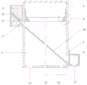
FIG. 2 is a sectional view of an improved acidification tank for embodying the internal structural design of the body of the acidification tank;
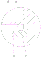
fig. 3 is an enlarged view of a portion a in fig. 2, for embodying the structural design of the portion a.
In the figure: 1. an acidification tank body; 2. a guide plate; 3. a cover plate; 4. a water outlet; 5. an electromagnetic valve; 6. a soil accommodating cavity; 7. a guide groove; 8. a squeegee; 9. an electric telescopic rod; 10. a filter screen; 11. a valve; 12. a water pump; 13. a motor; 14. a water outlet; 15. mesh openings; 16. a rotating table; 17. a roller; 18. and a support plate.
Detailed Description
In order to make the technical solutions of the present invention better understood, the following detailed description of the present invention is provided with reference to the accompanying drawings and specific embodiments, and it should be noted that the embodiments and features of the embodiments of the present invention can be combined with each other without conflict.
In the description of the present invention, it should be noted that the terms "upper", "lower", "inner", "outer", "top/bottom", and the like indicate orientations or positional relationships based on the orientations or positional relationships shown in the drawings, and are only for convenience of description and simplification of description, but do not indicate or imply that the device or element referred to must have a specific orientation, be constructed in a specific orientation, and be operated, and thus, should not be construed as limiting the present invention.
In the description of the present invention, it is to be noted that, unless otherwise explicitly specified or limited, the terms "mounted", "provided", "sleeved/connected", "connected", and the like are to be understood in a broad sense, such as "connected", which may be fixedly connected, detachably connected, or integrally connected; can be mechanically or electrically connected; they may be connected directly or indirectly through intervening media, or they may be interconnected between two elements. The specific meaning of the above terms in the present invention can be understood in specific cases to those skilled in the art.
An improved acidification tank, as shown in fig. 1, 2 and 3, comprises an acidification tank body 1, which can reduce the emission of pungent odor; a water outlet 14 is arranged at the bottom of the acidification tank body 1, and when the solution in the acidification tank body 1 needs to be replaced, the solution is discharged through the water outlet 14; the outer bottom of the acidification tank body 1 is fixedly connected with a motor 13, a rotating shaft of the motor 13 penetrates through the bottom of the acidification tank body 1 and is fixedly connected with a rotating table 16, and the rotating table 16 rotates under the action of the motor 13, so that the solution in the acidification tank body 1 can be stirred, and meanwhile, the acidification effect on a workpiece on the rotating table 16 can also be improved; the bottom of the rotating table 16 is provided with a plurality of meshes 15, so that the exchange between the solution in the rotating table 16 and the external solution can be enhanced, and the acidification effect is enhanced and accelerated; an annular supporting plate 18 is fixedly connected to the inner wall of the acidification tank body 1, a roller 17 is rotatably connected to the bottom of the rotating table 16, the roller 17 rolls on the supporting plate 18, the supporting plate 18 provides a supporting effect for the rotating table 16 to ensure the stability of the rotating table 16, and the arrangement of the roller 17 converts sliding friction into rolling friction, so that friction resistance is reduced; the bottom and the top of the acidification tank body 1 are respectively provided with a water inlet and a water outlet 4, a water suction pump 12 is connected between the water inlet and the water outlet 4 through a water pipe, and the water suction pump 12 pumps the solution at the bottom of the acidification tank body 1 to the top so as to circulate and mix the solutions at different depths.
As shown in fig. 1 and 2, a filter screen 10 which is obliquely arranged is fixedly connected in an acidification tank body 1, the filter screen 10 is arranged below a rotating table 16, residues generated in the acidification process of a workpiece fall onto the filter screen 10, a dirt holding cavity 6 communicated with the interior of the acidification tank body 1 is arranged on the outer side wall of the acidification tank body 1, the dirt holding cavity 6 is arranged at one end, close to the bottom of the acidification tank body 1, of the filter screen 10, an electromagnetic valve 5 is arranged at the joint between the dirt holding cavity 6 and the acidification tank body 1, and the electromagnetic valve 5 controls the communication or the closing between the acidification tank body 1 and the dirt holding cavity 6; arranging the water inlet at one end close to the sewage holding cavity 6, so that the suction force at the water inlet can drive the residues on the filter screen 10 to move towards the sewage holding cavity 6; the bottom of the sewage holding cavity 6 is designed into a funnel shape, so that the residue in the sewage holding cavity 6 can be conveniently discharged, the residue is reduced, a valve 11 is arranged at the bottom of the sewage holding cavity 6, and when the residue in the sewage holding cavity 6 is accumulated to a certain degree, the valve 11 is opened to discharge; keep away from one end fixedly connected with deflector 2 of soil accommodating cavity 6 on the lateral wall of acidizing pond body 1, be equipped with on deflector 2 with the guide way 7 of the inside intercommunication of acidizing pond body 1, and the bottom of guide way 7 and the upper surface parallel and level of filter screen 10, keep away from one end fixedly connected with electric telescopic handle 9 of filter screen 10 in guide way 7, fixedly connected with scraper blade 8 on electric telescopic handle 9, scraper blade 8 is used for clearing up remaining residue on the filter screen 10.
The cover plate 3 is opened to place the workpiece on the rotating table 16, the electromagnetic valve 5 enables the sewage containing cavity 6 to be communicated with the acidification tank body 1, the motor 13 is started to enable the rotating table 16 to rotate, meanwhile, the water suction pump 12 is started to pump the solution at the bottom of the acidification tank body 1 to the top, so that the solutions at different depths are circulated and mixed, and the acidification effect of the workpiece is accelerated and enhanced; residues generated in the acidification process of the workpiece fall onto the filter screen 10 and slide into the dirt holding cavity 6, when the residues in the dirt holding cavity 6 are accumulated to a certain degree, the electromagnetic valve 5 is closed, the valve 11 is opened to discharge the residues in the dirt holding cavity 6, the valve 11 is closed, the electromagnetic valve 5 is opened, and the dirt holding cavity 6 continues to collect the residues; after the certain time of acidizing, can accumulate on the filter screen 10 during the unable landing of partial residue is to receiving dirty chamber 6, electric telescopic handle 9 promotes scraper blade 8 and clears up filter screen 10, makes the residue that remains on it fall to receiving dirty chamber 6 in, has reduced the volume of the residue in acidizing pond body 1, makes the residue can not adsorb on the work piece and influence the acidizing effect of work piece.
It is above only the utility model discloses a preferred embodiment, the utility model discloses a scope of protection does not only confine above-mentioned embodiment, the all belongs to the utility model discloses a technical scheme under the thinking all belongs to the utility model discloses a scope of protection. It should be noted that, for those skilled in the art, various modifications and decorations can be made without departing from the principle of the present invention, and these modifications and decorations should also be regarded as the protection scope of the present invention.
Claims (8)
1. The utility model provides an improved generation acidizing pond, is including acidizing pond body (1), the inside fixedly connected with of acidizing pond body (1) is filter screen (10) that the slope set up, the inside of acidizing pond body (1) is equipped with rotation platform (16) that are located filter screen (10) top, its characterized in that: be equipped with on the lateral wall of acidizing pond body (1) with the inside pollutant uptake chamber (6) that communicates of acidizing pond body (1), pollutant uptake chamber (6) are located the one end that is close to the bottom of acidizing pond body (1) on filter screen (10), the junction between pollutant uptake chamber (6) and acidizing pond body (1) is equipped with solenoid valve (5), the bottom of pollutant uptake chamber (6) is equipped with valve (11), the bottom of acidizing pond body (1) is equipped with the water inlet, the top of acidizing pond body (1) is equipped with delivery port (4), there is suction pump (12) through the pipe connection between water inlet and delivery port (4), the water inlet is located the one end that is close to pollutant uptake chamber (6), be equipped with outlet (14) on acidizing pond body (1).
2. An improved acidification tank as defined in claim 1, wherein: fixedly connected with deflector (2) on the lateral wall of acidizing pond body (1), be equipped with guide way (7) with the inside intercommunication of acidizing pond body (1) on deflector (2), the bottom of guide way (7) and the upper surface parallel and level of filter screen (10), sliding connection has scraper blade (8) in guide way (7).
3. An improved acidification tank as claimed in claim 2, wherein: one end fixedly connected with electric telescopic handle (9) of keeping away from filter screen (10) in guide way (7), electric telescopic handle (9) and scraper blade (8) fixed connection.
4. An improved acidification tank as defined in claim 1, wherein: the bottom of the sewage containing cavity (6) is funnel-shaped.
5. An improved acidification tank as defined in claim 1, wherein: the outer bottom fixedly connected with motor (13) of acidizing pond body (1), the pivot of motor (13) runs through acidizing pond body (1) and with revolving stage (16) fixed connection.
6. An improved acidification tank as defined in claim 1, wherein: the inner wall of the acidification tank body (1) is fixedly connected with an annular supporting plate (18), and the bottom of the rotating table (16) is provided with a roller (17) which is in contact with the supporting plate (18).
7. An improved acidification tank as defined in claim 1, wherein: the bottom of the rotating table (16) is provided with a plurality of meshes (15).
8. An improved acidification tank as defined in claim 1, wherein: the top of the acidification tank body (1) is rotatably connected with a cover plate (3).
Priority Applications (1)
| Application Number | Priority Date | Filing Date | Title |
|---|---|---|---|
| CN202020368739.9U CN211814655U (en) | 2020-03-23 | 2020-03-23 | Improved generation acidizing pond |
Applications Claiming Priority (1)
| Application Number | Priority Date | Filing Date | Title |
|---|---|---|---|
| CN202020368739.9U CN211814655U (en) | 2020-03-23 | 2020-03-23 | Improved generation acidizing pond |
Publications (1)
| Publication Number | Publication Date |
|---|---|
| CN211814655U true CN211814655U (en) | 2020-10-30 |
Family
ID=73010338
Family Applications (1)
| Application Number | Title | Priority Date | Filing Date |
|---|---|---|---|
| CN202020368739.9U Active CN211814655U (en) | 2020-03-23 | 2020-03-23 | Improved generation acidizing pond |
Country Status (1)
| Country | Link |
|---|---|
| CN (1) | CN211814655U (en) |
Cited By (2)
| Publication number | Priority date | Publication date | Assignee | Title |
|---|---|---|---|---|
| CN112941530A (en) * | 2021-01-19 | 2021-06-11 | 李艳玲 | Blank descaling device for gear forging |
| CN113355660A (en) * | 2021-04-30 | 2021-09-07 | 冀美霖 | Alloy catalysis equipment for metal surface treatment process |
-
2020
- 2020-03-23 CN CN202020368739.9U patent/CN211814655U/en active Active
Cited By (3)
| Publication number | Priority date | Publication date | Assignee | Title |
|---|---|---|---|---|
| CN112941530A (en) * | 2021-01-19 | 2021-06-11 | 李艳玲 | Blank descaling device for gear forging |
| CN112941530B (en) * | 2021-01-19 | 2022-09-06 | 山西联益锻造股份有限公司 | Blank descaling device for gear forging |
| CN113355660A (en) * | 2021-04-30 | 2021-09-07 | 冀美霖 | Alloy catalysis equipment for metal surface treatment process |
Similar Documents
| Publication | Publication Date | Title |
|---|---|---|
| CN211814655U (en) | Improved generation acidizing pond | |
| CN211247104U (en) | Machine parts spraying device | |
| CN210279545U (en) | Spraying device convenient to prevent chemical industry coating from condensing | |
| CN212370006U (en) | Photocatalyst processing is with agitating unit's washing structure | |
| CN216458376U (en) | High-efficient mixing stirring device of chemical material | |
| CN212944639U (en) | Ecological environment prosthetic devices | |
| CN212469212U (en) | Portable soil prosthetic devices for gardens | |
| CN214572182U (en) | Clean type zinc-plated heating device | |
| CN213316470U (en) | Carborundum miropowder pickling installation | |
| CN212655665U (en) | Silt solidification treatment device is dredged in water conservancy river course | |
| CN212631978U (en) | Filtering chip removal device | |
| CN209669175U (en) | Fermentation cabin is used in a kind of production of blueberry wine | |
| CN112374718A (en) | Sedimentation device for sludge treatment with high sedimentation rate | |
| CN216837459U (en) | Paint spraying chamber sewage treatment plant convenient to lacquer sediment is rejected | |
| CN208613246U (en) | A kind of diamond cleaning device of easy-unloading | |
| CN108856121A (en) | A kind of diamond cleaning device of easy-unloading | |
| CN217264954U (en) | A deoiling formula effluent treatment plant for green construction | |
| CN218131568U (en) | Preparation device for self-cleaning coating liquid | |
| CN219503993U (en) | Automatic flux feeding device | |
| CN220345301U (en) | Laboratory sewage treatment device | |
| CN215626997U (en) | Environment engineering sewage treatment pond device | |
| CN219209569U (en) | Superfine active heavy calcium carbonate surface coating machine | |
| CN218485285U (en) | Terpene is effluent treatment plant for production line convenient to operation | |
| CN219596394U (en) | Galvanized part surface treating agent premixing device | |
| CN215391192U (en) | Diamond micropowder acid dip pickle |
Legal Events
| Date | Code | Title | Description |
|---|---|---|---|
| GR01 | Patent grant | ||
| GR01 | Patent grant |