CN211812233U - Multi-angle adjustable metal waste grabbing device - Google Patents
Multi-angle adjustable metal waste grabbing device Download PDFInfo
- Publication number
- CN211812233U CN211812233U CN202020364397.3U CN202020364397U CN211812233U CN 211812233 U CN211812233 U CN 211812233U CN 202020364397 U CN202020364397 U CN 202020364397U CN 211812233 U CN211812233 U CN 211812233U
- Authority
- CN
- China
- Prior art keywords
- base
- rod
- plate
- angle adjustable
- screw
- Prior art date
- Legal status (The legal status is an assumption and is not a legal conclusion. Google has not performed a legal analysis and makes no representation as to the accuracy of the status listed.)
- Expired - Fee Related
Links
Images


Abstract
The utility model discloses a multi-angle adjustable metal waste gripping device, which comprises a bottom plate and a gripping mechanism; the side edge of the bottom plate is fixedly provided with an upright post, the top of the upright post is provided with a top plate, and the lower side of the top plate is provided with the grabbing mechanism; the grabbing mechanism comprises an installation plate, a base and clamping blocks, wherein a second screw rod is rotatably installed at the bottom of the installation plate, the base is fixedly installed at the bottom of the installation plate, the base is rotatably connected with the second screw rod, and the two clamping blocks are symmetrically hinged to the left side and the right side of the bottom of the base; the left side and the right side of the base of the second screw rod are symmetrically provided with two external threads with opposite rotation directions, and the left side and the right side of the second screw rod are also symmetrically in threaded connection with two second thread sleeves. The utility model discloses an utilize first motor and second motor to carry out multidirectional regulation to the position of snatching the mechanism, and then snatch metal waste fast and stably.
Description
Technical Field
The utility model relates to a metal waste snatchs technical field, specifically is an adjustable metal waste grabbing device of multi-angle.
Background
The scrap metal is a metal or alloy product which loses use value temporarily, general scrap metal contains useful metals or harmful elements, and in recent ten years, each person calculates the quantity of scrap metal boxes in municipal waste on average every year, 74 kilograms in the United states, 29 kilograms in the United kingdom, 21 kilograms in France and 810 ten thousand tons in Japan 1978 of industrial scrap metal.
After the existing metal waste is compacted into blocks, the blocks generally need to be grabbed and hoisted by using modes such as a crane, and the steel cable can shake when moving during carrying, so that an operator is not suitable for use, accidents are easy to occur, and the operation is unsafe.
SUMMERY OF THE UTILITY MODEL
An object of the utility model is to provide an adjustable metal waste grabbing device of multi-angle to solve the problem that proposes in the above-mentioned background art.
In order to achieve the above object, the utility model provides a following technical scheme:
a multi-angle adjustable metal waste grabbing device comprises a bottom plate and a grabbing mechanism; the side edge of the bottom plate is fixedly provided with an upright post, the top of the upright post is provided with a top plate, and the lower side of the top plate is provided with the grabbing mechanism; the grabbing mechanism comprises an installation plate, a base and clamping blocks, wherein a second screw rod is rotatably installed at the bottom of the installation plate, the base is fixedly installed at the bottom of the installation plate, the base is rotatably connected with the second screw rod, and the two clamping blocks are symmetrically hinged to the left side and the right side of the bottom of the base; the left and right sides symmetry that the second screw rod is located the base is provided with two kinds of external screw threads that revolve to opposite, and the left and right sides of second screw rod is symmetrical threaded connection still has two second swivel nuts, the upside and the mounting panel sliding connection of second swivel nut, and the connecting rod is installed in the downside of second swivel nut is articulated, and the other end and the clamp splice of connecting rod are articulated.
As a further aspect of the present invention: and a third motor for driving the second screw rod to rotate is fixedly mounted on the mounting plate.
As a further aspect of the present invention: a plurality of telescopic cylinders are uniformly and fixedly installed between the two clamping blocks at the bottom of the base, and vacuum chucks are fixedly installed at the telescopic ends of the telescopic cylinders.
As a further aspect of the present invention: the roof passes through the rotation axis and rotates and installs on the stand, and the bottom of roof is rotated and is installed first screw rod, and the bottom of roof still fixed mounting has the slide bar, threaded connection has first swivel nut on the first screw rod, first swivel nut and slide bar sliding connection, and the bottom fixed mounting of first swivel nut has electric telescopic handle, and electric telescopic handle's flexible end passes through the link and snatchs mechanism fixed connection.
As a further aspect of the present invention: the outside fixed mounting of stand has the first motor that drives rotation axis pivoted, the bottom fixed mounting of roof has the second motor that drives first screw rod pivoted.
As a further aspect of the present invention: the clamping block is provided with a pressing plate on one side close to a clamped material, the pressing plate is fixedly connected with the clamping block through a plurality of connecting pieces, each connecting piece comprises a slot formed in the clamping block and an inserting rod fixedly installed in the corresponding slot, the inserting rods are slidably installed in the slots, and the inserting rods are fixedly connected with the slots through connecting springs.
Compared with the prior art, the beneficial effects of the utility model are that: the utility model discloses the mechanism that snatchs that downside at the roof is provided with drives two second swivel nuts and removes or move dorsad through the rotation of second screw rod, and then drives the clamp splice and rotate, carries out the centre gripping to metal waste when two clamp splices rotate in opposite directions, drives metal waste and removes, carries out multidirectional regulation to the position of snatching the mechanism through utilizing first motor and second motor simultaneously, and then snatchs metal waste fast and stably.
Drawings
FIG. 1 is a schematic structural diagram of a multi-angle adjustable metal scrap gripping device.
FIG. 2 is a schematic structural diagram of a grabbing mechanism in the multi-angle adjustable metal waste grabbing device.
FIG. 3 is a schematic structural diagram of a clamping block in the multi-angle adjustable metal scrap grabbing device.
FIG. 4 is a schematic structural diagram of a grabbing mechanism in the embodiment 2 of the multi-angle adjustable metal scrap grabbing device.
Fig. 5 is a partially enlarged schematic view of a portion a of fig. 4.
In the figure: 1-bottom plate, 2-upright post, 3-first motor, 4-top plate, 5-rotating shaft, 6-first screw, 7-first thread sleeve, 8-sliding rod, 9-second motor, 10-electric telescopic rod, 11-connecting frame, 12-grabbing mechanism, 13-mounting plate, 14-second screw, 15-base, 16-third motor, 17-second thread sleeve, 18-connecting rod, 19-clamping block, 20-telescopic cylinder, 21-connecting piece, 22-inserting rod, 23-slot and 24-connecting spring.
Detailed Description
The technical solutions in the embodiments of the present invention will be described clearly and completely with reference to the accompanying drawings in the embodiments of the present invention, and it is obvious that the described embodiments are only some embodiments of the present invention, not all embodiments. Based on the embodiments in the present invention, all other embodiments obtained by a person skilled in the art without creative work belong to the protection scope of the present invention.
Example 1
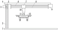
Referring to fig. 1 to 3, in an embodiment of the present invention, a multi-angle adjustable metal scrap gripping device includes a bottom plate 1 and a gripping mechanism 12; the side edge of the bottom plate 1 is fixedly provided with an upright post 2, the top of the upright post 2 is provided with a top plate 4, and the lower side of the top plate 4 is provided with the grabbing mechanism 12;
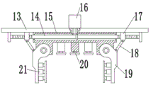
the grabbing mechanism 12 comprises a mounting plate 13, a base 15 and clamping blocks 19, a second screw 14 is rotatably mounted at the bottom of the mounting plate 13, the base 15 is fixedly mounted at the bottom of the mounting plate 13, the base 15 is rotatably connected with the second screw 14, and the two clamping blocks 19 are symmetrically hinged to the left side and the right side of the bottom of the base 15; the second screw 14 is symmetrically provided with two types of external threads with opposite rotation directions on the left side and the right side of the base 15, the left side and the right side of the second screw 14 are further symmetrically in threaded connection with two second threaded sleeves 17, the upper sides of the second threaded sleeves 17 are slidably connected with the mounting plate 13, the lower sides of the second threaded sleeves 17 are hinged with connecting rods 18, the other ends of the connecting rods 18 are hinged with clamping blocks 19, the two second threaded sleeves 17 are driven to move oppositely or move reversely by the rotation of the second screw 14, so that the clamping blocks 19 are driven to rotate, and when the two clamping blocks 19 rotate oppositely, the metal scrap is clamped, so that the metal scrap is driven to move;
specifically, in this embodiment, the mounting plate 13 is further fixedly mounted with a third motor 16 for driving the second screw 14 to rotate;
a plurality of telescopic cylinders 20 are uniformly and fixedly arranged between the two clamping blocks 19 at the bottom of the base 15, vacuum chucks are fixedly arranged at the telescopic ends of the telescopic cylinders 20, and the telescopic cylinders 20 drive the vacuum chucks to be close to the metal waste to adsorb the metal waste;
the top plate 4 is rotatably installed on the upright post 2 through a rotating shaft 5, a first screw 6 is rotatably installed at the bottom of the top plate 4, a sliding rod 8 is further fixedly installed at the bottom of the top plate 4, a first threaded sleeve 7 is connected to the first screw 6 in a threaded mode, the first threaded sleeve 7 is connected with the sliding rod 8 in a sliding mode, an electric telescopic rod 10 is fixedly installed at the bottom of the first threaded sleeve 7, and the telescopic end of the electric telescopic rod 10 is fixedly connected with a grabbing mechanism 12 through a connecting frame 11;
specifically, in this embodiment, the outside fixed mounting of stand 2 has the first motor 3 that drives rotation axis 5 pivoted, the bottom fixed mounting of roof 4 has the second motor 9 that drives first screw 6 pivoted.
Example 2
Referring to fig. 1 to 3, in an embodiment of the present invention, a multi-angle adjustable metal scrap gripping device includes a bottom plate 1 and a gripping mechanism 12; the side edge of the bottom plate 1 is fixedly provided with an upright post 2, the top of the upright post 2 is provided with a top plate 4, and the lower side of the top plate 4 is provided with the grabbing mechanism 12;
the grabbing mechanism 12 comprises a mounting plate 13, a base 15 and clamping blocks 19, a second screw 14 is rotatably mounted at the bottom of the mounting plate 13, the base 15 is fixedly mounted at the bottom of the mounting plate 13, the base 15 is rotatably connected with the second screw 14, and the two clamping blocks 19 are symmetrically hinged to the left side and the right side of the bottom of the base 15; the second screw 14 is symmetrically provided with two types of external threads with opposite rotation directions on the left side and the right side of the base 15, the left side and the right side of the second screw 14 are further symmetrically in threaded connection with two second threaded sleeves 17, the upper sides of the second threaded sleeves 17 are slidably connected with the mounting plate 13, the lower sides of the second threaded sleeves 17 are hinged with connecting rods 18, the other ends of the connecting rods 18 are hinged with clamping blocks 19, the two second threaded sleeves 17 are driven to move oppositely or move reversely by the rotation of the second screw 14, so that the clamping blocks 19 are driven to rotate, and when the two clamping blocks 19 rotate oppositely, the metal scrap is clamped, so that the metal scrap is driven to move;
specifically, in this embodiment, the mounting plate 13 is further fixedly mounted with a third motor 16 for driving the second screw 14 to rotate;
a plurality of telescopic cylinders 20 are uniformly and fixedly arranged between the two clamping blocks 19 at the bottom of the base 15, vacuum chucks are fixedly arranged at the telescopic ends of the telescopic cylinders 20, and the telescopic cylinders 20 drive the vacuum chucks to be close to the metal waste to adsorb the metal waste;
the top plate 4 is rotatably installed on the upright post 2 through a rotating shaft 5, a first screw 6 is rotatably installed at the bottom of the top plate 4, a sliding rod 8 is further fixedly installed at the bottom of the top plate 4, a first threaded sleeve 7 is connected to the first screw 6 in a threaded mode, the first threaded sleeve 7 is connected with the sliding rod 8 in a sliding mode, an electric telescopic rod 10 is fixedly installed at the bottom of the first threaded sleeve 7, and the telescopic end of the electric telescopic rod 10 is fixedly connected with a grabbing mechanism 12 through a connecting frame 11;
specifically, in this embodiment, the outside fixed mounting of stand 2 has the first motor 3 that drives rotation axis 5 pivoted, the bottom fixed mounting of roof 4 has the second motor 9 that drives first screw 6 pivoted.
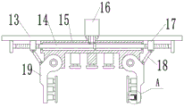
Referring to fig. 4 and 5, the present embodiment is different from embodiment 1 in that:
the clamping block 19 is provided with a pressing plate on one side close to the clamped material, the pressing plate is fixedly connected with the clamping block 19 through a plurality of connecting pieces 21, each connecting piece 21 comprises a slot 23 formed in the clamping block 19 and an inserting rod 22 fixedly installed on the corresponding inserting rod, the inserting rod 22 is slidably installed in the slot 23, and the inserting rod 22 is fixedly connected with the slot 23 through a connecting spring 24.
It is obvious to a person skilled in the art that the invention is not restricted to details of the above-described exemplary embodiments, but that it can be implemented in other specific forms without departing from the spirit or essential characteristics of the invention. The present embodiments are therefore to be considered in all respects as illustrative and not restrictive, the scope of the invention being indicated by the appended claims rather than by the foregoing description, and all changes which come within the meaning and range of equivalency of the claims are therefore intended to be embraced therein. Any reference sign in a claim should not be construed as limiting the claim concerned.
Furthermore, it should be understood that although the present description refers to embodiments, not every embodiment may contain only a single embodiment, and such description is for clarity only, and those skilled in the art should integrate the description, and the embodiments may be combined as appropriate to form other embodiments understood by those skilled in the art.
Claims (6)
1. The multi-angle adjustable metal waste grabbing device is characterized by comprising a bottom plate (1) and a grabbing mechanism (12); the side edge of the bottom plate (1) is fixedly provided with an upright post (2), the top of the upright post (2) is provided with a top plate (4), and the lower side of the top plate (4) is provided with the grabbing mechanism (12); the grabbing mechanism (12) comprises a mounting plate (13), a base (15) and clamping blocks (19), a second screw rod (14) is rotatably mounted at the bottom of the mounting plate (13), the base (15) is fixedly mounted at the bottom of the mounting plate (13), the base (15) is rotatably connected with the second screw rod (14), and the left side and the right side of the bottom of the base (15) are symmetrically hinged with the two clamping blocks (19); the left side and the right side of the second screw rod (14) on the base (15) are symmetrically provided with two external threads with opposite rotating directions, the left side and the right side of the second screw rod (14) are further symmetrically in threaded connection with two second thread sleeves (17), the upper side of each second thread sleeve (17) is in sliding connection with the mounting plate (13), the lower side of each second thread sleeve (17) is hinged to a connecting rod (18), and the other end of each connecting rod (18) is hinged to the clamping block (19).
2. The multi-angle adjustable metal scrap gripping device according to claim 1, wherein a third motor (16) for driving the second screw (14) to rotate is fixedly mounted on the mounting plate (13).
3. The multi-angle adjustable metal scrap gripping device according to claim 2, wherein a plurality of telescopic cylinders (20) are uniformly and fixedly installed between the two clamping blocks (19) at the bottom of the base (15), and vacuum suction cups are fixedly installed at the telescopic ends of the telescopic cylinders (20).
4. The multi-angle adjustable metal waste grabbing device of claim 1, wherein the top plate (4) is rotatably mounted on the column (2) through a rotating shaft (5), a first screw (6) is rotatably mounted at the bottom of the top plate (4), a sliding rod (8) is fixedly mounted at the bottom of the top plate (4), a first threaded sleeve (7) is connected onto the first screw (6) in a threaded manner, the first threaded sleeve (7) is slidably connected with the sliding rod (8), an electric telescopic rod (10) is fixedly mounted at the bottom of the first threaded sleeve (7), and the telescopic end of the electric telescopic rod (10) is fixedly connected with the grabbing mechanism (12) through a connecting frame (11).
5. The multi-angle adjustable metal scrap gripping device according to claim 4, wherein a first motor (3) for driving the rotating shaft (5) to rotate is fixedly installed on the outer side of the upright post (2), and a second motor (9) for driving the first screw rod (6) to rotate is fixedly installed at the bottom of the top plate (4).
6. The multi-angle adjustable metal scrap gripping device according to any one of claims 1 to 5, wherein a pressing plate is arranged on one side of the clamping block (19) close to the clamped material, the pressing plate is fixedly connected with the clamping block (19) through a plurality of connecting pieces (21), each connecting piece (21) comprises a slot (23) formed in the clamping block (19) and an insertion rod (22) fixedly installed in the corresponding slot (23), the insertion rod (22) is slidably installed in the corresponding slot (23), and the insertion rod (22) is fixedly connected with the corresponding slot (23) through a connecting spring (24).
Priority Applications (1)
| Application Number | Priority Date | Filing Date | Title |
|---|---|---|---|
| CN202020364397.3U CN211812233U (en) | 2020-03-20 | 2020-03-20 | Multi-angle adjustable metal waste grabbing device |
Applications Claiming Priority (1)
| Application Number | Priority Date | Filing Date | Title |
|---|---|---|---|
| CN202020364397.3U CN211812233U (en) | 2020-03-20 | 2020-03-20 | Multi-angle adjustable metal waste grabbing device |
Publications (1)
| Publication Number | Publication Date |
|---|---|
| CN211812233U true CN211812233U (en) | 2020-10-30 |
Family
ID=73010618
Family Applications (1)
| Application Number | Title | Priority Date | Filing Date |
|---|---|---|---|
| CN202020364397.3U Expired - Fee Related CN211812233U (en) | 2020-03-20 | 2020-03-20 | Multi-angle adjustable metal waste grabbing device |
Country Status (1)
| Country | Link |
|---|---|
| CN (1) | CN211812233U (en) |
-
2020
- 2020-03-20 CN CN202020364397.3U patent/CN211812233U/en not_active Expired - Fee Related
Similar Documents
| Publication | Publication Date | Title |
|---|---|---|
| CN107176469B (en) | Special industrial stacking robot for shared bicycle assembly line production | |
| CN208631655U (en) | A kind of lumber elevator of plate workshop | |
| CN211812233U (en) | Multi-angle adjustable metal waste grabbing device | |
| CN104843481B (en) | A kind of warp beam handling device | |
| CN215471099U (en) | Intelligent grabbing device for machine manufacturing | |
| CN212312058U (en) | Turn over a packet arm for production line convenient to press from both sides and get | |
| CN214418794U (en) | Handling device for hardware stamping die | |
| CN209937775U (en) | Tire forming clamp | |
| CN209697736U (en) | A kind of welding wire production Multifunctional pay-off stand | |
| CN218049774U (en) | A novel bender for round pin axle processing | |
| CN217570645U (en) | Cable straightening equipment for municipal engineering | |
| CN216969754U (en) | Special transportation device for moving and changing power facilities of power distribution network along highway | |
| CN213196290U (en) | Portable electric welding machine | |
| CN214236015U (en) | Firm multi-functional shaped steel muscle bending machine | |
| CN218081164U (en) | Welding fixture for frame of carrier | |
| CN215364510U (en) | Electric power overhauls uses instrument centre gripping equipment | |
| CN219172468U (en) | Fitment is with material handling device convenient to it is fixed | |
| CN218320248U (en) | Hoist and mount formula jumbo size part's removal machine | |
| CN211003043U (en) | Building engineering is with removing brick clamp and getting device | |
| CN215179610U (en) | Portable fluorescent observation box | |
| CN219851842U (en) | Auxiliary bending and extruding device for power rush-repair | |
| CN220251368U (en) | Chain block test bench | |
| CN212776324U (en) | Fixed mounting device of equipment | |
| CN214771646U (en) | Dismounting tool for stator of oil transfer pump | |
| CN213531027U (en) | Cutting device for metal component |
Legal Events
| Date | Code | Title | Description |
|---|---|---|---|
| GR01 | Patent grant | ||
| GR01 | Patent grant | ||
| CF01 | Termination of patent right due to non-payment of annual fee | ||
| CF01 | Termination of patent right due to non-payment of annual fee |
Granted publication date: 20201030 |