CN211802951U - Dust absorbing device for machining - Google Patents
Dust absorbing device for machining Download PDFInfo
- Publication number
- CN211802951U CN211802951U CN202020344803.XU CN202020344803U CN211802951U CN 211802951 U CN211802951 U CN 211802951U CN 202020344803 U CN202020344803 U CN 202020344803U CN 211802951 U CN211802951 U CN 211802951U
- Authority
- CN
- China
- Prior art keywords
- dust
- fixedly connected
- collecting box
- water
- machining
- Prior art date
- Legal status (The legal status is an assumption and is not a legal conclusion. Google has not performed a legal analysis and makes no representation as to the accuracy of the status listed.)
- Expired - Fee Related
Links
Images
Abstract
The utility model discloses a dust absorbing device for machining, which belongs to the field of machining and comprises a collecting box, a hinge and a box cover, wherein one side of the front surface of the collecting box is movably connected with one side of the front surface of the box cover through the hinge, the bottom of the collecting box is fixedly provided with a roller, the top of one side of the collecting box is fixedly connected with a mounting sleeve, the inside of the mounting sleeve is fixedly sleeved with an air pump, the bottom of the air pump is fixedly connected with the inside of the collecting box through an air inlet pipe, and the top of the air pump is fixedly connected with an air exhaust pipe; this dust absorbing device for machining through setting up storage water tank, drinking-water pipe, water pump, inlet tube, defeated water jacket and atomising head, can utilize the adhesion of water smoke to increase the weight of dust self at the in-process that the dust subsides for the dust can be because of gravity increase falls fast, has accelerated the settling velocity of dust, thereby has improved the effect of subsiding of dust.
Description
Technical Field
The utility model belongs to the technical field of machining, concretely relates to dust absorbing device for machining.
Background
Machining refers to a process of changing the overall dimension or performance of a workpiece through a mechanical device, if the machining precision is required to be improved, parts need to be accurately positioned, however, after each mechanical part is machined, more dust remains on the surface of a workbench, if the parts are directly placed on the workbench for positioning, dimension deviation can be caused, errors occur in positioning, and therefore the parts need to be cleaned.
It can be known at present according to a machining dust collection device of application number 201822197401.7, this application utilizes the round brush earlier with the dust perk of adhesion on the processing platform, be convenient for follow-up through vacuum suction collect the dust, the processing platform surface is cleaned to the round brush simultaneously, the cleanliness factor of processing platform and the reliability of dust collection have been improved to utilize the support frame can remove the suction box to arbitrary position at will, guaranteed the flexibility that the dust was collected, however, this application scheme is at the in-process of in-service use, still has following defect: (1) in the application, the dust is discharged into the dust collection box by the exhaust pipe, and is settled by the gravity of the dust, but the falling speed of the dust is slow due to the light weight of the dust, so that the settling effect of the dust is poor; (2) when the roller brush is used for a long time, a great amount of dirt is adhered to the surface of the roller brush, and even the roller brush is damaged, but the application does not describe how to disassemble, clean or replace the roller brush, and therefore, a dust absorption device for machining is provided.
SUMMERY OF THE UTILITY MODEL
An object of the utility model is to provide a dust absorbing device for machining to solve the problem that proposes among the above-mentioned background art.
In order to achieve the above object, the utility model provides a following technical scheme: a dust absorption device for machining comprises a collecting box, a hinge and a box cover, wherein one side of the front face of the collecting box is movably connected with one side of the front face of the box cover through the hinge, rollers are fixedly arranged at the bottom of the collecting box, a mounting sleeve is fixedly connected to the top of one side of the collecting box, an air suction pump is fixedly sleeved inside the mounting sleeve, the bottom of the air suction pump is fixedly connected with the inside of the collecting box through an air inlet pipe, an air suction pipe is fixedly connected to the top of the air suction pump, a dust hood is fixedly connected to the bottom end of the air suction pipe, a positioning rod is fixedly connected to one side of the top of the dust hood, a positioning plate is movably sleeved outside the positioning rod, a rolling brush is arranged inside the dust hood, a protective cover is fixedly connected to one side of the dust hood, a transmission motor is fixedly arranged inside the protective, one end of the transmission shaft is fixedly connected with one end of the rolling brush through a coupler, the other side of the dust hood is movably sleeved with a movable rod, a transverse plate is fixedly connected inside the collecting box, a dust collecting box is arranged at the top of the transverse plate, a water storage tank is fixedly connected at the bottom of the inner cavity of the collecting box, a water pumping pipe is fixedly sleeved in the water storage tank, a water pump is fixedly connected at the bottom end of the water pumping pipe, one side of the water pump is fixedly connected with a water inlet pipe, the top end of the water inlet pipe is fixedly connected with a water delivery sleeve, the bottom of the water delivery sleeve is fixedly provided with a spray head, the middle part of the top end of the collecting box is fixedly sleeved with an exhaust pipe, the bottom end of the exhaust pipe is fixedly connected with an exhaust hood, and the top thread of blast pipe has cup jointed the filter sleeve, the inside fixed mounting of filter sleeve has the active carbon board, and one side thread of filter sleeve has cup jointed the outlet duct.
As a preferred embodiment, the positioning plate is fixedly arranged at the bottom of one side of the collecting box, and the positioning plate is matched with the positioning rod.
In a preferred embodiment, the rolling brush is in the shape of a cylinder, and the surface of the rolling brush is fixedly connected with bristles.
As a preferred embodiment, the number of the couplers is two, the two couplers are equal in size, and the two couplers are respectively located at two ends of the rolling brush and fixedly connected with one end of the transmission shaft and one end of the movable rod.
In a preferred embodiment, the number of the spray heads is five, the five spray heads are equal in size, and the five spray heads are equidistantly distributed at the bottom of the water conveying sleeve.
In a preferred embodiment, the activated carbon plate is formed by pressing activated carbon particles, and the activated carbon plate is matched with the inner cavity of the filter sleeve.
Compared with the prior art, the beneficial effects of the utility model are that:
according to the dust absorption device for machining, by arranging the water storage tank, the water pumping pipe, the water pump, the water inlet pipe, the water conveying sleeve and the atomizing spray head, the weight of dust can be increased by utilizing the adhesion of water mist in the dust settling process, so that the dust can fall quickly due to the increase of gravity, the settling speed of the dust is increased, and the settling effect of the dust is improved;
this dust absorbing device for machining, through setting up transmission shaft, shaft coupling and movable rod, can be at the absorptive in-process of dust, can carry out the dismouting to the round brush to be convenient for clear up the dirty on round brush surface, and when the round brush damaged, also be convenient for dismantle the change to the round brush, set up locating lever and locating plate simultaneously, can be when the dust is not cleared up, be convenient for put the suction hood, thereby guaranteed the stability that the suction hood placed.
Drawings
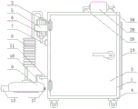
FIG. 1 is a schematic front view of the structure of the present invention;
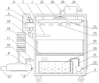
FIG. 2 is a schematic view of the inside of the collection box of the present invention;
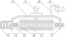
FIG. 3 is a cross-sectional view of the suction hood of the present invention;
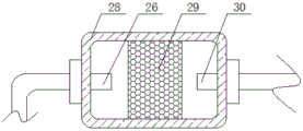
fig. 4 is a cross-sectional view of the filter sleeve of the present invention.
In the figure: 1. a collection box; 2. a hinge; 3. a box cover; 4. a roller; 5. installing a sleeve; 6. an air pump; 7. an air inlet pipe; 8. an air exhaust pipe; 9. a dust hood; 10. positioning a rod; 11. positioning a plate; 12. rolling and brushing; 13. a protective cover; 14. a drive motor; 15. a drive shaft; 16. a coupling; 17. a movable rod; 18. a transverse plate; 19. a dust collecting box; 20. a water storage tank; 21. a water pumping pipe; 22. a water pump; 23. a water inlet pipe; 24. a water delivery sleeve; 25. a spray head; 26. an exhaust pipe; 27. an exhaust hood; 28. a filter sleeve; 29. an activated carbon plate; 30. and an air outlet pipe.
Detailed Description
The present invention will be further described with reference to the following examples.
The following examples are intended to illustrate the invention, but are not intended to limit the scope of the invention. The condition in the embodiment can be further adjusted according to concrete condition the utility model discloses a it is right under the design prerequisite the utility model discloses a simple improvement of method all belongs to the utility model discloses the scope of claiming.
Referring to fig. 1 and 2, the present invention provides a dust absorption device for machining, including a collection box 1, a hinge 2 and a box cover 3, in order to facilitate the absorption of dust by negative pressure, one side of the front of the collection box 1 is movably connected with one side of the front of the box cover 3 through the hinge 2, a roller 4 is fixedly installed at the bottom of the collection box 1, a mounting sleeve 5 is fixedly connected at the top of one side of the collection box 1, an air pump 6 is fixedly sleeved inside the mounting sleeve 5, the bottom of the air pump 6 is fixedly connected with the inside of the collection box 1 through an air inlet pipe 7, an air exhaust pipe 8 is fixedly connected at the top of the air pump 6, a dust hood 9 is fixedly connected at the bottom of the air exhaust pipe 8, a positioning rod 10 is fixedly connected at one side of the top of the dust hood 9, a positioning plate 11 is movably sleeved outside the positioning rod 10, and the positioning plate 11 is fixedly installed, and looks adaptation between locating plate 11 and the locating lever 10, when starting aspiration pump 6, utilize exhaust tube 8 to extract, and make the inside of suction hood 9 produce the negative pressure, exhaust tube 8 of taking again, aim at the processing platform with the bottom of suction hood 9, thereby be convenient for utilize the negative pressure to absorb the dust on the processing platform, if the suction hood 9 needs to be placed, can aim at locating plate 11 with locating lever 10, and insert locating lever 10 to the inside of locating plate 11, thereby be convenient for put dust hood 9.
Referring to fig. 1, 2 and 3, in order to enhance the dust absorption effect, a rolling brush 12 may be disposed inside the dust hood 9, the rolling brush 12 is shaped like a cylinder, bristles are fixedly connected to the surface of the rolling brush 12, a protective cover 13 is fixedly connected to one side of the dust hood 9, a transmission motor 14 is fixedly mounted inside the protective cover 13, a transmission shaft 15 is fixedly sleeved on an output shaft of the transmission motor 14, when the transmission motor 14 is turned on, the transmission shaft 15 rotates and drives the rolling brush 12 to rotate, so that dust adhered to the processing table can be separated from the processing table under the driving of the rolling brush 12, thereby facilitating the dust absorption and enhancing the dust absorption effect.
Referring to fig. 1, 2 and 3, in order to facilitate the disassembly and assembly of the rolling brush 12, one end of the transmission shaft 15 is fixedly connected with one end of the rolling brush 12 through the coupler 16, the movable rod 17 is movably sleeved on the other side of the dust hood 9, the number of the couplers 16 is two, the two couplers 16 are equal in size, the two couplers 16 are respectively positioned at two ends of the rolling brush 12 and fixedly connected with one ends of the transmission shaft 15 and the movable rod 17, when the bolt on the coupler 16 is rotated, the rolling brush 12 can be separated from the transmission shaft 15 and the movable rod 17, so that the disassembly and assembly of the rolling brush 12 are facilitated, and the dirt on the rolling brush 12 can be cleaned.
Referring to fig. 1 and 2, in order to accelerate the settling speed of dust, a horizontal plate 18 is fixedly connected inside the collection box 1, a dust receiving box 19 is placed on the top of the horizontal plate 18, a water storage tank 20 is fixedly connected to the bottom of the inner cavity of the collection box 1, a water pumping pipe 21 is fixedly sleeved inside the water storage tank 20, a water pump 22 is fixedly connected to the bottom end of the water pumping pipe 21, a water inlet pipe 23 is fixedly connected to one side of the water pump 22, a water delivery sleeve 24 is fixedly connected to the top end of the water inlet pipe 23, spray heads 25 are fixedly installed at the bottom of the water delivery sleeve 24, the number of the spray heads 25 is five, the size of the five spray heads 25 is equal, the five spray heads 25 are equidistantly distributed at the bottom of the water delivery sleeve 24, when absorbed dust enters the interior of the collection box 1 from the air inlet pipe 7, the water pump 22 is started, the water in the water storage tank 20 is extracted by the water pumping pipe 21, and the extracted, make the water spray out with the form of water smoke from atomising head 25, when the dust contacted water smoke, can increase the weight of dust self, be convenient for accelerate the settling velocity of dust to the dust fall effect of dust has been improved.
Referring to fig. 1, 2 and 4, in order to filter and purify the exhausted air, an exhaust pipe 26 is fixedly sleeved at the middle part of the top end of the collecting box 1, an exhaust hood 27 is fixedly connected at the bottom end of the exhaust pipe 26, a filter sleeve 28 is sleeved at the top end of the exhaust pipe 26 in a threaded manner, an activated carbon plate 29 is fixedly arranged in the filter sleeve 28, and the activated carbon plate 29 is formed by pressing activated carbon particles, the active carbon plate 29 is matched with the inner cavity of the filter sleeve 28, an air outlet pipe 30 is sleeved on one side of the filter sleeve 28 in a threaded manner, when the pressure inside the collecting tank 1 increases, the dusted air flows upward and enters the exhaust pipe 26 from the exhaust hood 27, and enters the filter sleeve 28 through the exhaust pipe 26, at this time, the activated carbon plate 29 absorbs and filters the dust remained in the air, thereby facilitating the filtering and purification of the discharged air, and the purified air will flow from the outlet duct 30 to the atmosphere.
In the above scheme, it should be noted that: rubber pads are arranged among the collecting box 1, the hinge 2 and the box cover 3, and when the box cover 3 is in a closed state, the sealing performance in the collecting box 1 can be guaranteed; the coupling 16 is composed of two connecting plates and two bolts, and the two connecting plates are respectively and fixedly connected with the end part of the rolling brush 12 and one end of the transmission shaft 15 (or the movable rod 17); the cross plate 18 is adapted to the inner cavity of the collecting container 1 and the cross plate 18 can separate the interior of the collecting container 1 into two separate spaces, while the air between the two spaces is not circulated.
The utility model discloses a theory of operation and use flow: firstly, the air pump 6 is started, the air pump 8 is used for pumping, negative pressure is generated inside the dust hood 9, then the air pump 8 is taken, the bottom of the dust hood 9 is aligned to the processing table, so that dust on the processing table can be conveniently sucked by the negative pressure, if the dust hood 9 needs to be placed, the positioning rod 10 can be aligned to the positioning plate 11, the positioning rod 10 is inserted into the positioning plate 11, so that the dust hood 9 can be conveniently placed, meanwhile, the transmission motor 14 is opened, the transmission shaft 15 is rotated, the roller brush 12 is driven to rotate, dust adhered to the processing table can be separated from the processing table under the driving of the roller brush 12, so that the dust is conveniently adsorbed, the dust absorption effect is enhanced, then, when the absorbed dust enters the collecting box 1 from the air inlet pipe 7, the water pump 22 is started, and water inside the water storage tank 20 is pumped by the water pump 21, and the extracted water body enters the water conveying sleeve 24 from the water inlet pipe 23, so that the water body is sprayed out from the atomizing spray head 25 in the form of water mist, when dust contacts the water mist, the weight of the dust is increased, the settling speed of the dust is convenient to accelerate, and the dust settling effect of the dust is improved, finally, along with the increase of the internal pressure of the collecting box 1, the air after dust settling flows upwards, enters the exhaust pipe 26 from the exhaust hood 27, and enters the filter sleeve 28 through the exhaust pipe 26, at the moment, the activated carbon plate 29 adsorbs and filters the dust remained in the air, so that the exhausted air is convenient to filter and purify, the purified air flows to the atmosphere from the air outlet pipe 30, and meanwhile, the rolling brush 12 can be separated from the transmission shaft 15 and the movable rod 17 by rotating the bolt on the coupler 16, so as to be convenient for dismounting the rolling brush 12, so that it is possible to clean dirt on the roll brush 12 or to replace the damaged roll brush 12.
Although embodiments of the present invention have been shown and described, it will be appreciated by those skilled in the art that changes, modifications, substitutions and alterations can be made in these embodiments without departing from the principles and spirit of the invention, the scope of which is defined in the appended claims and their equivalents.
Claims (6)
1. The utility model provides a dust absorbing device for machining, includes collecting box (1), hinge (2) and case lid (3), its characterized in that: the front side of the collecting box (1) is movably connected with the front side of the box cover (3) through a hinge (2), the bottom of the collecting box (1) is fixedly provided with a roller (4), the top of one side of the collecting box (1) is fixedly connected with a mounting sleeve (5), the inside of the mounting sleeve (5) is fixedly sleeved with an air pump (6), the bottom of the air pump (6) is fixedly connected with the inside of the collecting box (1) through an air inlet pipe (7), the top of the air pump (6) is fixedly connected with an air exhaust pipe (8), the bottom of the air exhaust pipe (8) is fixedly connected with a dust hood (9), one side of the top of the dust hood (9) is fixedly connected with a positioning rod (10), the outside of the positioning rod (10) is movably sleeved with a positioning plate (11), the inside of the dust hood (9) is provided with a rolling brush (12), and one side of the dust hood (9) is fixedly connected with a, the inside fixed mounting of safety cover (13) has drive motor (14), fixed transmission shaft (15) having cup jointed on the output shaft of drive motor (14), the one end fixed connection of shaft coupling (16) and round brush (12) is passed through to the one end of transmission shaft (15), movable rod (17) have been cup jointed in the opposite side activity of suction hood (9), the inside fixedly connected with diaphragm (18) of collecting box (1), dust collecting box (19) have been placed at the top of diaphragm (18), the bottom fixedly connected with storage water tank (20) of collecting box (1) inner chamber, drinking-water pipe (21) have been cup jointed to the inside fixing of storage water tank (20), the bottom fixedly connected with water pump (22) of drinking-water pipe (21), one side fixedly connected with inlet tube (23) of water pump (22), the top fixedly connected with water delivery cover (24) of inlet tube (23), the bottom fixed mounting of water conveying cover (24) has atomising head (25), the fixed blast pipe (26) that has cup jointed in middle part on collecting box (1) top, the bottom fixedly connected with exhaust hood (27) of blast pipe (26), and the top screw thread of blast pipe (26) has cup jointed filter sleeve (28), the inside fixed mounting of filter sleeve (28) has activated carbon plate (29), and one side screw thread of filter sleeve (28) has cup jointed outlet duct (30).
2. The machining dust suction device according to claim 1, wherein: the positioning plate (11) is fixedly arranged at the bottom of one side of the collecting box (1), and the positioning plate (11) is matched with the positioning rod (10).
3. The machining dust suction device according to claim 1, wherein: the rolling brush (12) is cylindrical, and the surface of the rolling brush (12) is fixedly connected with bristles.
4. The machining dust suction device according to claim 1, wherein: the quantity of shaft coupling (16) is two, and the size of two shaft couplings (16) equals, two shaft coupling (16) are located the both ends of round brush (12) respectively and with the one end fixed connection of transmission shaft (15) and movable rod (17).
5. The machining dust suction device according to claim 1, wherein: the quantity of atomising head (25) is five, and the size of five atomising heads (25) equals, five atomising head (25) equidistance distributes in the bottom of water delivery cover (24).
6. The machining dust suction device according to claim 1, wherein: the activated carbon plate (29) is formed by pressing activated carbon particles, and the activated carbon plate (29) is matched with the inner cavity of the filter sleeve (28).
Priority Applications (1)
| Application Number | Priority Date | Filing Date | Title |
|---|---|---|---|
| CN202020344803.XU CN211802951U (en) | 2020-03-18 | 2020-03-18 | Dust absorbing device for machining |
Applications Claiming Priority (1)
| Application Number | Priority Date | Filing Date | Title |
|---|---|---|---|
| CN202020344803.XU CN211802951U (en) | 2020-03-18 | 2020-03-18 | Dust absorbing device for machining |
Publications (1)
| Publication Number | Publication Date |
|---|---|
| CN211802951U true CN211802951U (en) | 2020-10-30 |
Family
ID=73012641
Family Applications (1)
| Application Number | Title | Priority Date | Filing Date |
|---|---|---|---|
| CN202020344803.XU Expired - Fee Related CN211802951U (en) | 2020-03-18 | 2020-03-18 | Dust absorbing device for machining |
Country Status (1)
| Country | Link |
|---|---|
| CN (1) | CN211802951U (en) |
Cited By (3)
| Publication number | Priority date | Publication date | Assignee | Title |
|---|---|---|---|---|
| CN112643795A (en) * | 2021-01-12 | 2021-04-13 | 陶小妹 | Cutting equipment for log processing |
| CN114029264A (en) * | 2021-11-08 | 2022-02-11 | 林国火 | Aluminium foil material environmental protection processing system |
| CN116098302A (en) * | 2023-02-10 | 2023-05-12 | 中金辐照武汉有限公司 | Food irradiation treatment device |
-
2020
- 2020-03-18 CN CN202020344803.XU patent/CN211802951U/en not_active Expired - Fee Related
Cited By (5)
| Publication number | Priority date | Publication date | Assignee | Title |
|---|---|---|---|---|
| CN112643795A (en) * | 2021-01-12 | 2021-04-13 | 陶小妹 | Cutting equipment for log processing |
| CN114029264A (en) * | 2021-11-08 | 2022-02-11 | 林国火 | Aluminium foil material environmental protection processing system |
| CN114029264B (en) * | 2021-11-08 | 2022-11-04 | 河南润鑫新材料股份有限公司 | Aluminum foil material environmental protection processing system |
| CN116098302A (en) * | 2023-02-10 | 2023-05-12 | 中金辐照武汉有限公司 | Food irradiation treatment device |
| CN116098302B (en) * | 2023-02-10 | 2024-01-30 | 中金辐照武汉有限公司 | Food irradiation treatment device |
Similar Documents
| Publication | Publication Date | Title |
|---|---|---|
| CN211802951U (en) | Dust absorbing device for machining | |
| CN108815968A (en) | A kind of device of workshop good dedusting effect | |
| CN109881618B (en) | Road sweeper | |
| CN113772449B (en) | Powder metallurgy dust removing device and dust removing process | |
| CN212788386U (en) | High-efficient dust collecting equipment | |
| CN212189765U (en) | Sheet metal part spraying equipment with drying function | |
| CN208167630U (en) | A kind of road administration environmental protection catkin removing machine | |
| CN217432082U (en) | Uniform paint spraying device for surface of metal product plate | |
| CN209952506U (en) | Low-cost efficient dust collector | |
| CN109281279B (en) | High-efficiency energy-saving cleaning system for ground washing vehicle | |
| CN108867504A (en) | One kind being used for pressure suction cleaning device for environmental sanitation works | |
| CN103169421B (en) | A kind of gasoline power dust collector | |
| CN113181734A (en) | Dust treatment device for rubber processing with self-cleaning filter plates | |
| CN216223471U (en) | Electrical engineering and dust collector for automation equipment thereof | |
| CN219212820U (en) | Shot blasting machine with dust removal function | |
| CN218358361U (en) | Smoke absorbing and recycling mechanism | |
| CN213833444U (en) | Conveyer belt with adsorption equipment | |
| CN211070494U (en) | Efficient cyclone for grain and oil production | |
| CN216572244U (en) | Electromechanical engineering workshop environmental protection dust collector | |
| CN218794688U (en) | Dust collector is used to fitment | |
| CN217668609U (en) | Accurate double-end grass rumble machine of environmental protection dust removal | |
| CN218962146U (en) | Dust fall fog gun machine for solid waste treatment | |
| CN220498876U (en) | Shot blasting machine device convenient for dust removal | |
| CN219898543U (en) | Dust collector for water pump housing processing workshop | |
| CN219744297U (en) | Paint mist separating device for coating production line |
Legal Events
| Date | Code | Title | Description |
|---|---|---|---|
| GR01 | Patent grant | ||
| GR01 | Patent grant | ||
| CF01 | Termination of patent right due to non-payment of annual fee | ||
| CF01 | Termination of patent right due to non-payment of annual fee |
Granted publication date: 20201030 |