CN211745505U - Crawler-type orchard pruning and branch crushing all-in-one machine - Google Patents
Crawler-type orchard pruning and branch crushing all-in-one machine Download PDFInfo
- Publication number
- CN211745505U CN211745505U CN202020227271.1U CN202020227271U CN211745505U CN 211745505 U CN211745505 U CN 211745505U CN 202020227271 U CN202020227271 U CN 202020227271U CN 211745505 U CN211745505 U CN 211745505U
- Authority
- CN
- China
- Prior art keywords
- wall
- branch
- dust removal
- wheel
- crushing
- Prior art date
- Legal status (The legal status is an assumption and is not a legal conclusion. Google has not performed a legal analysis and makes no representation as to the accuracy of the status listed.)
- Expired - Fee Related
Links
Images


Landscapes
- Crushing And Pulverization Processes (AREA)
Abstract
The utility model discloses a garrulous branch all-in-one of beta orchard beta pruning, including mounting panel, garrulous branch mechanism and dust removal case, the below of garrulous branch mechanism one side is provided with the discharge gate, and installs the protection casing in the outside of discharge gate below, the one end of protection casing is fixed with the dust removal case through the connecting pipe, and the one end inner wall of dust removal case installs the fan, install the filter screen between the both ends inner wall of dust removal case. The utility model discloses an install the protection casing in the outside of discharge gate below, the one end of protection casing is fixed with the dust removal case through the connecting pipe, and the one end inner wall of dust removal case installs the fan, installs the filter screen between the both ends inner wall of dust removal case, can raise a large amount of dusts after garrulous branch is discharged, inhales the dust removal incasement through the fan, then filters through the filter screen, realizes flying upward of less fine dust bits in the air, less environmental pollution.
Description
Technical Field
The utility model relates to the technical field of agricultural machinery, specifically be a garrulous branch all-in-one of crawler-type orchard beta pruning.
Background
The fruit tree pruning is a measure for regulating the relationship between the growth and the fruit of the fruit tree, and the fruit tree pruning also needs to coordinate the distribution of various branches, fully utilize the illumination condition and regulate the nutrient distribution so as to lead the fruit tree to bear fruits early, produce fruits early, stably produce fruits and prolong the full bearing period and the economic life. Therefore, the pruning of the fruit trees is crucial to the growth of the fruit trees; if the manual pruning method is adopted, the working efficiency is low, a large amount of physical strength of workers is consumed, and the pruning operation cost is not reduced.
With the development of the pruning technology, a pruning machine appears, most of the traditional pruning machines only have a single pruning function, and the processing of the pruned branches by workers is complex, so that a device for smashing the branches is needed, the branches continue to be returned to the field after being smashed, a large amount of manpower is saved, the fertilization cost is reduced, and the pruning and pruning integrated machine is needed.
Moreover, the existing crawler-type orchard pruning and branch crushing all-in-one machine does not have the functions of a pruning mechanism, such as convenience in height and angle adjustment, stable movement of the device and less dust and scraps.
SUMMERY OF THE UTILITY MODEL
An object of the utility model is to provide a garrulous branch all-in-one of crawler-type orchard beta pruning to the current garrulous branch all-in-one of crawler-type orchard beta pruning that proposes in solving above-mentioned background art does not have the function problem that pruning mechanism is convenient for height-adjusting angle, device remove firm and less dirt bits.
In order to achieve the above object, the utility model provides a following technical scheme: a crawler-type orchard pruning and branch breaking integrated machine comprises a mounting plate, a branch breaking mechanism and a dust removal box, wherein driving wheels are uniformly mounted at two ends of the mounting plate, a second driven wheel is mounted at two ends of one side of the mounting plate, a first driven wheel is mounted at two ends of the other side of the mounting plate, two sides of the top end of the mounting plate are connected with a support plate through support rods, a cab is mounted at one side of the top end of the support plate, a controller is mounted on the inner wall of one side of the cab, a loop bar is mounted below the inside of the cab, a threaded rod is mounted on the inner side of the loop bar, an adjusting knob is arranged at the top end of the loop bar, a steel wire line is mounted on the inner side of the threaded rod, an electric push rod is mounted at the top end of the support plate, the top end, and the top of branch crushing mechanism is provided with the feed inlet, first motor is installed on the top of feed inlet one side branch crushing mechanism, and the one end of first motor is connected in the one end of second crushing wheel through first belt, the below of branch crushing mechanism one side is provided with the discharge gate, and installs the protection casing in the outside of discharge gate below, the one end of protection casing is fixed with the dust removal case through the connecting pipe, and the one end inner wall of dust removal case installs the fan, install the filter screen between the both ends inner wall of dust removal case.
Preferably, the second motor is installed on the top of mounting panel, and the one end of second motor passes through the one end of second belt fixed connection in action wheel.
Preferably, install the track between the outer wall of first follow driving wheel and second follow driving wheel, and the interior outer wall of track all evenly is provided with the tooth piece to the top of track is provided with the protective cover.
Preferably, a rotating shaft is installed between the inner walls of the two sides of the loop bar, the bottom end of the steel wire is fixedly connected to the outer wall of the rotating shaft, a rocking handle is arranged on one side of the rotating shaft, and the outer wall of the steel wire is fixedly connected with a foot pressing plate through a connecting wire.
Preferably, the top end of the steel wire is hinged with a movable blade, and the top end of a threaded rod on one side of the movable blade is provided with a fixed blade.
Preferably, a second crushing wheel is installed between the inner walls of the two ends of the branch crushing mechanism, a first crushing wheel is installed between the inner walls of the two ends of the branch crushing mechanism below the second crushing wheel, and the toothed cutters between the first crushing wheel and the second crushing wheel are meshed with each other.
Compared with the prior art, the beneficial effects of the utility model are that:
(1) through installing adjust knob, the foot clamp plate, electric putter, the threaded rod, remove the blade, fixed blade, the steel wire line, the apparatus further comprises a rotating shaft, threaded rod and rocking handle, through rotatory adjust knob, adjust knob inner wall screw thread and threaded rod outer wall screw-thread fit, the threaded rod makes progress or moves down, be convenient for adjust the height of threaded rod, again according to the high rotatory rocking handle, can make the winding change at the epaxial steel wire of commentaries on classics elongated or shorten, then step on the foot clamp plate through the foot, can make the steel wire line remove downwards, make the removal blade to one side of fixed blade remove, cut the branch between removal blade and the fixed blade, and stretch out and draw back through electric putter, the inclination of adjustable threaded rod, it is.
(2) The device is through installing tooth piece, track, first from driving wheel and second from the driving wheel simultaneously, and first follow driving wheel and second follow the rotation from the driving wheel to make the track remove on ground, set up a plurality of tooth pieces simultaneously, the rotatory card of tooth piece advances in the ground, makes the device remove more stable, gliding phenomenon can not appear, makes the staff safer.
(3) The device is through installing discharge gate, filter screen, fan and dust removal case simultaneously, and the crushed aggregates passes through discharge gate discharge back, can raise a large amount of dust in the air, inhales the dust removal incasement through the fan, then filters through the filter screen, realizes flying upward of less fine dust bits in the air, less environmental pollution.
Drawings
FIG. 1 is a schematic cross-sectional view of the device of the present invention;
FIG. 2 is a schematic structural view of the dust removing mechanism of the present invention;
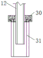
fig. 3 is a schematic structural view of an adjusting knob of the present invention;
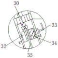
fig. 4 is an enlarged schematic view of the structure at a of the present invention;
in the figure: 1. a protective cover; 2. a discharge port; 3. a first crushing wheel; 4. a second crushing wheel; 5. a first belt; 6. a branch breaking mechanism; 7. a first motor; 8. a feed inlet; 9. an electric push rod; 10. moving the blade; 11. fixing a blade; 12. a threaded rod; 13. a cab; 14. a controller; 15. a foot pressing plate; 16. a support plate; 17. a first driven wheel; 18. a support bar; 19. a tooth block; 20. mounting a plate; 21. a crawler belt; 22. a second belt; 23. a second motor; 24. a driving wheel; 25. a second driven wheel; 26. a protective cover; 27. a fan; 28. a filter screen; 29. a dust removal box; 30. adjusting a knob; 31. a loop bar; 32. a rotating shaft; 33. a rocking handle; 34. a steel wire; 35. and connecting the wires.
Detailed Description
The technical solutions in the embodiments of the present invention will be described clearly and completely with reference to the accompanying drawings in the embodiments of the present invention, and it is obvious that the described embodiments are only some embodiments of the present invention, not all embodiments. Based on the embodiments in the present invention, all other embodiments obtained by a person skilled in the art without creative work belong to the protection scope of the present invention.
Referring to fig. 1-4, the present invention provides an embodiment: a crawler-type orchard pruning and branch breaking integrated machine comprises a mounting plate 20, a branch breaking mechanism 6 and a dust removal box 29, wherein driving wheels 24 are uniformly mounted at two ends of the mounting plate 20;
the top end of the mounting plate 20 is provided with a second motor 23, the model of the second motor 23 can be Y90S-2, and one end of the second motor 23 is fixedly connected to one end of the driving wheel 24 through a second belt 22, when in use, the second motor 23 drives the second belt 22 to rotate through the operation of the second motor 23, so that the driving wheel 24 is driven by the second belt 22 to rotate;
the two ends of one side of the mounting plate 20 are both provided with second driven wheels 25, and the two ends of the other side of the mounting plate 20 are both provided with first driven wheels 17;
when the device is used, the first driven wheel 17 and the second driven wheel 25 rotate, the first driven wheel 17 and the second driven wheel 25 drive the crawler 21 to rotate simultaneously, so that the crawler 21 moves on the ground, the plurality of tooth blocks 19 are arranged simultaneously, and the tooth blocks 19 are rotationally clamped into the ground, so that the device is more stable to move, the sliding phenomenon cannot occur, and the working personnel are safer;
the two sides of the top end of the mounting plate 20 are connected with a support plate 16 through support rods 18, a cab 13 is mounted on one side of the top end of the support plate 16, a controller 14 is mounted on the inner wall of one side of the cab 13, the type of the controller 14 can be ARGUS, a loop bar 31 is mounted below the interior of the cab 13, a threaded rod 12 is mounted on the inner side of the loop bar 31, an adjusting knob 30 is arranged at the top end of the loop bar 31, and a steel wire 34 is mounted on the inner side of the threaded rod 12;
a rotating shaft 32 is arranged between the inner walls of the two sides of the loop bar 31, the bottom end of the steel wire 34 is fixedly connected to the outer wall of the rotating shaft 32, a rocking handle 33 is arranged on one side of the rotating shaft 32, the outer wall of the steel wire 34 is fixedly connected with a foot pressing plate 15 through a connecting wire 35, when the loop bar is used, the steel wire 34 wound on the rotating shaft 32 can be lengthened or shortened by rotating the rocking handle 33, and then the steel wire 34 can move downwards by stepping on the foot pressing plate 15;
the top end of the steel wire 34 is hinged with the movable blade 10, and the top end of the threaded rod 12 on one side of the movable blade 10 is provided with the fixed blade 11, when the movable cutting tool is used, the steel wire 34 moves downwards, so that the movable blade 10 moves towards one side of the fixed blade 11, and branches between the movable blade 10 and the fixed blade 11 are cut, and the operation is simple;
an electric push rod 9 is installed at the top end of the supporting plate 16, the model of the electric push rod 9 can be ANT-35, the top end of the electric push rod 9 is hinged to the bottom end of the threaded rod 12, a branch crushing mechanism 6 is installed on the other side of the top end of the supporting plate 16, and a feeding hole 8 is formed in the top end of the branch crushing mechanism 6;
the second crushing wheel 4 is arranged between the inner walls of the two ends of the branch crushing mechanism 6, the first crushing wheel 3 is arranged between the inner walls of the two ends of the branch crushing mechanism 6 below the second crushing wheel 4, the toothed knives between the first crushing wheel 3 and the second crushing wheel 4 are meshed with each other, when the tree branch crushing mechanism is used, the first crushing wheel 3 and the toothed knives between the second crushing wheel 4 are meshed with each other, the second crushing wheel 4 drives the first crushing wheel 3 to rotate in the opposite direction to crush tree branches, and the knife edges on the toothed knives crush the tree branches;
a first motor 7 is installed at the top end of the branch crushing mechanism 6 on one side of the feeding hole 8, the model of the first motor 7 can be Y315M-2, one end of the first motor 7 is connected to one end of the second crushing wheel 4 through a first belt 5, a discharging hole 2 is arranged below one side of the branch crushing mechanism 6, a protective cover 26 is installed on the outer side below the discharging hole 2, a dust removing box 29 is fixed at one end of the protective cover 26 through a connecting pipe, a fan 27 is installed on the inner wall of one end of the dust removing box 29, the model of the fan 27 can be GD30K2-12, and a filter screen 28 is installed between the inner walls of two ends of the dust removing box 29;
the single chip microcomputer in the controller 14 is electrically connected with the first motor 7, the electric push rod 9, the second motor 23 and the fan 27 through conducting wires.
The working principle is as follows: when the crawler belt is used, the second motor 23 drives the second belt 22 to rotate through the work of the second motor 23, so that the second belt 22 drives the driving wheel 24 to rotate, and the driving wheel 24 drives the crawler belt 21 to rotate simultaneously;
the first driven wheel 17 and the second driven wheel 25 rotate along with the first driven wheel, so that the crawler 21 moves on the ground, and meanwhile, the plurality of tooth blocks 19 are arranged, and the tooth blocks 19 are rotationally clamped into the ground, so that the device moves more stably, the sliding phenomenon cannot occur, and the safety of workers is improved;
the adjusting knob 30 is rotated, the threads on the inner wall of the adjusting knob 30 are matched with the threads on the outer wall of the threaded rod 12, the threaded rod 12 moves upwards or downwards, the height of the threaded rod 12 is convenient to adjust, the rocking handle 33 is rotated according to the height, the steel wire 34 wound on the rotating shaft 32 can be lengthened or shortened, then the foot pressing plate 15 is stepped on by feet, the steel wire 34 can move downwards, the moving blade 10 moves towards one side of the fixed blade 11, branches between the moving blade 10 and the fixed blade 11 are cut off, the inclination angle of the threaded rod 12 can be adjusted through the stretching of the electric push rod 9, and the use is more flexible;
the branches enter the branch crushing mechanism 6 through the feed inlet 8, and are meshed with each other through the toothed knives between the first crushing wheel 3 and the second crushing wheel 4, the second crushing wheel 4 drives the first crushing wheel 3 to rotate in the opposite direction to crush the branches, and the knife edges on the toothed knives crush the branches;
after the crushed aggregates are discharged through the discharge port 2, a large amount of dust can be lifted in the air, the dust is sucked into the dust removal box 29 through the fan 27, and then the dust is filtered through the filter screen 28, so that less fine dust in the air can be lifted, and less environmental pollution is caused.
It is obvious to a person skilled in the art that the invention is not restricted to details of the above-described exemplary embodiments, but that it can be implemented in other specific forms without departing from the spirit or essential characteristics of the invention. The present embodiments are therefore to be considered in all respects as illustrative and not restrictive, the scope of the invention being indicated by the appended claims rather than by the foregoing description, and all changes which come within the meaning and range of equivalency of the claims are therefore intended to be embraced therein. Any reference sign in a claim should not be construed as limiting the claim concerned.
Claims (6)
1. The utility model provides a garrulous branch all-in-one of crawler-type orchard beta pruning, includes mounting panel, branch crushing mechanism and dust removal case, its characterized in that: the branch cutting machine is characterized in that driving wheels are uniformly arranged at two ends of the mounting plate, second driven wheels are arranged at two ends of one side of the mounting plate, first driven wheels are arranged at two ends of the other side of the mounting plate, two sides of the top end of the mounting plate are connected with supporting plates through supporting rods, a cab is arranged at one side of the top end of the supporting plates, a controller is arranged on the inner wall of one side of the cab, a loop bar is arranged below the interior of the cab, a threaded rod is arranged on the inner side of the loop bar, an adjusting knob is arranged at the top end of the loop bar, a steel wire is arranged on the inner side of the threaded rod, an electric push rod is arranged at the top end of the supporting plate, the top end of the electric push rod is hinged to the bottom end of the threaded rod, a branch cutting mechanism is arranged at the other, and the one end of first motor is connected in the one end of second crushing wheel through first belt, the below of branch crushing mechanism one side is provided with the discharge gate, and installs the protection casing in the outside of discharge gate below, the one end of protection casing is fixed with the dust removal case through the connecting pipe, and the one end inner wall of dust removal case installs the fan, install the filter screen between the both ends inner wall of dust removal case.
2. The crawler-type orchard pruning and branch crushing all-in-one machine according to claim 1, characterized in that: the second motor is installed on the top of mounting panel, and the one end of second motor passes through the one end of second belt fixed connection in the action wheel.
3. The crawler-type orchard pruning and branch crushing all-in-one machine according to claim 1, characterized in that: install the track between the outer wall of first follow driving wheel and second follow driving wheel, and the interior outer wall of track all evenly is provided with the tooth piece to the top of track is provided with the protective cover.
4. The crawler-type orchard pruning and branch crushing all-in-one machine according to claim 1, characterized in that: the rotating shaft is installed between the inner walls of the two sides of the loop bar, the bottom end of the steel wire is fixedly connected to the outer wall of the rotating shaft, a rocking handle is arranged on one side of the rotating shaft, and the outer wall of the steel wire is fixedly connected with a foot pressing plate through a connecting wire.
5. The crawler-type orchard pruning and branch crushing all-in-one machine according to claim 1, characterized in that: the top end of the steel wire is hinged with a movable blade, and the top end of a threaded rod on one side of the movable blade is provided with a fixed blade.
6. The crawler-type orchard pruning and branch crushing all-in-one machine according to claim 1, characterized in that: install the second between the both ends inner wall of branch crushing mechanism and smash the wheel, and second smashes and installs first crushing wheel between the both ends inner wall of wheel below branch crushing mechanism to serrated knife intermeshing between first crushing wheel and the second crushing wheel.
Priority Applications (1)
| Application Number | Priority Date | Filing Date | Title |
|---|---|---|---|
| CN202020227271.1U CN211745505U (en) | 2020-02-28 | 2020-02-28 | Crawler-type orchard pruning and branch crushing all-in-one machine |
Applications Claiming Priority (1)
| Application Number | Priority Date | Filing Date | Title |
|---|---|---|---|
| CN202020227271.1U CN211745505U (en) | 2020-02-28 | 2020-02-28 | Crawler-type orchard pruning and branch crushing all-in-one machine |
Publications (1)
| Publication Number | Publication Date |
|---|---|
| CN211745505U true CN211745505U (en) | 2020-10-27 |
Family
ID=72910276
Family Applications (1)
| Application Number | Title | Priority Date | Filing Date |
|---|---|---|---|
| CN202020227271.1U Expired - Fee Related CN211745505U (en) | 2020-02-28 | 2020-02-28 | Crawler-type orchard pruning and branch crushing all-in-one machine |
Country Status (1)
| Country | Link |
|---|---|
| CN (1) | CN211745505U (en) |
-
2020
- 2020-02-28 CN CN202020227271.1U patent/CN211745505U/en not_active Expired - Fee Related
Similar Documents
| Publication | Publication Date | Title |
|---|---|---|
| CN111011025B (en) | Road greening trimming means for municipal works | |
| CN216820739U (en) | Lawn trimming means for garden management | |
| CN211745505U (en) | Crawler-type orchard pruning and branch crushing all-in-one machine | |
| CN207252417U (en) | A kind of forest harvesting residue collection device | |
| CN205922147U (en) | Park maintenance uses grass and trees trimming means | |
| CN111152279A (en) | Cutting device is used in handicraft production of recoverable leftover bits | |
| CN215269594U (en) | Standardized fruit tree trimming means | |
| CN208191230U (en) | A kind of novel garden plantation perforating device | |
| CN207995688U (en) | A kind of air blowing type grass trimmer | |
| CN210551601U (en) | Full-automatic program-controlled paper cutter | |
| CN214852962U (en) | Tea tree trimming device for tea planting | |
| CN212978674U (en) | Raw material crushing device for shaving board production | |
| CN213847745U (en) | Quick pruning operation mechanism for greening | |
| CN209226268U (en) | A kind of safe and efficient mica tape cutting machine | |
| CN112871404A (en) | Grinder is used in duck feed production | |
| CN216772934U (en) | Wire detects with abandonment electric wire processing apparatus | |
| CN214939104U (en) | Pavement construction is with milling plane device | |
| CN219961428U (en) | Novel afforestation pruning tool car | |
| CN216573286U (en) | Thermal power plant lime-ash processing apparatus | |
| CN211329664U (en) | Gardens are with automatic reducing mechanism of withered branch | |
| CN218193089U (en) | Numerical control plasma gantry cutting machine with dust removal structure | |
| CN219373022U (en) | Greenhouse vegetable plants with device that loosens soil | |
| CN219685720U (en) | Cutting knife structure | |
| CN212331185U (en) | Cutting device is used in handicraft production of recoverable leftover bits | |
| CN109644715A (en) | A kind of new-type Multifunctional garden branch trimming device |
Legal Events
| Date | Code | Title | Description |
|---|---|---|---|
| GR01 | Patent grant | ||
| GR01 | Patent grant | ||
| CF01 | Termination of patent right due to non-payment of annual fee | ||
| CF01 | Termination of patent right due to non-payment of annual fee |
Granted publication date: 20201027 Termination date: 20210228 |