CN211740831U - Spinning type coarse-grained soil triaxial experiment sample preparation device - Google Patents
Spinning type coarse-grained soil triaxial experiment sample preparation device Download PDFInfo
- Publication number
- CN211740831U CN211740831U CN202020064226.9U CN202020064226U CN211740831U CN 211740831 U CN211740831 U CN 211740831U CN 202020064226 U CN202020064226 U CN 202020064226U CN 211740831 U CN211740831 U CN 211740831U
- Authority
- CN
- China
- Prior art keywords
- spinning
- sample preparation
- circular arc
- rigid
- reaction
- Prior art date
- Legal status (The legal status is an assumption and is not a legal conclusion. Google has not performed a legal analysis and makes no representation as to the accuracy of the status listed.)
- Expired - Fee Related
Links
- 239000002689 soil Substances 0.000 title claims abstract description 66
- 238000002360 preparation method Methods 0.000 title claims abstract description 60
- 238000009987 spinning Methods 0.000 title claims abstract description 60
- 238000002474 experimental method Methods 0.000 title claims abstract description 7
- 238000012360 testing method Methods 0.000 claims abstract description 19
- XLYOFNOQVPJJNP-UHFFFAOYSA-N water Substances O XLYOFNOQVPJJNP-UHFFFAOYSA-N 0.000 claims description 24
- 239000012528 membrane Substances 0.000 claims description 14
- 238000005070 sampling Methods 0.000 claims description 10
- 235000017166 Bambusa arundinacea Nutrition 0.000 claims description 4
- 235000017491 Bambusa tulda Nutrition 0.000 claims description 4
- 241001330002 Bambuseae Species 0.000 claims description 4
- 235000015334 Phyllostachys viridis Nutrition 0.000 claims description 4
- 239000011425 bamboo Substances 0.000 claims description 4
- 230000006978 adaptation Effects 0.000 claims description 2
- 230000006835 compression Effects 0.000 abstract description 2
- 238000007906 compression Methods 0.000 abstract description 2
- 239000000523 sample Substances 0.000 description 97
- 238000000034 method Methods 0.000 description 5
- 238000010586 diagram Methods 0.000 description 4
- POIUWJQBRNEFGX-XAMSXPGMSA-N cathelicidin Chemical compound C([C@@H](C(=O)N[C@@H](CCCNC(N)=N)C(=O)N[C@@H](CCCCN)C(=O)N[C@@H](CO)C(=O)N[C@@H](CCCCN)C(=O)N[C@@H](CCC(O)=O)C(=O)N[C@@H](CCCCN)C(=O)N[C@@H]([C@@H](C)CC)C(=O)NCC(=O)N[C@@H](CCCCN)C(=O)N[C@@H](CCC(O)=O)C(=O)N[C@@H](CC=1C=CC=CC=1)C(=O)N[C@@H](CCCCN)C(=O)N[C@@H](CCCNC(N)=N)C(=O)N[C@@H]([C@@H](C)CC)C(=O)N[C@@H](C(C)C)C(=O)N[C@@H](CCC(N)=O)C(=O)N[C@@H](CCCNC(N)=N)C(=O)N[C@@H]([C@@H](C)CC)C(=O)N[C@@H](CCCCN)C(=O)N[C@@H](CC(O)=O)C(=O)N[C@@H](CC=1C=CC=CC=1)C(=O)N[C@@H](CC(C)C)C(=O)N[C@@H](CCCNC(N)=N)C(=O)N[C@@H](CC(N)=O)C(=O)N[C@@H](CC(C)C)C(=O)N[C@@H](C(C)C)C(=O)N1[C@@H](CCC1)C(=O)N[C@@H](CCCNC(N)=N)C(=O)N[C@@H]([C@@H](C)O)C(=O)N[C@@H](CCC(O)=O)C(=O)N[C@@H](CO)C(O)=O)NC(=O)[C@H](CC=1C=CC=CC=1)NC(=O)[C@H](CC(O)=O)NC(=O)CNC(=O)[C@H](CC(C)C)NC(=O)[C@@H](N)CC(C)C)C1=CC=CC=C1 POIUWJQBRNEFGX-XAMSXPGMSA-N 0.000 description 3
- 238000003825 pressing Methods 0.000 description 3
- 238000005056 compaction Methods 0.000 description 2
- 229910000831 Steel Inorganic materials 0.000 description 1
- 230000001680 brushing effect Effects 0.000 description 1
- 239000011362 coarse particle Substances 0.000 description 1
- 238000012669 compression test Methods 0.000 description 1
- 239000013068 control sample Substances 0.000 description 1
- 238000009826 distribution Methods 0.000 description 1
- 239000010419 fine particle Substances 0.000 description 1
- 238000004519 manufacturing process Methods 0.000 description 1
- 239000000463 material Substances 0.000 description 1
- 238000005259 measurement Methods 0.000 description 1
- 238000011017 operating method Methods 0.000 description 1
- 230000000149 penetrating effect Effects 0.000 description 1
- 238000000926 separation method Methods 0.000 description 1
- 239000010959 steel Substances 0.000 description 1
- 238000005303 weighing Methods 0.000 description 1
Images




Landscapes
- Investigating Strength Of Materials By Application Of Mechanical Stress (AREA)
- Sampling And Sample Adjustment (AREA)
Abstract
The utility model relates to the field of experimental equipment for soil mechanical property test of geotechnical engineering subject, in particular to a spinning coarse-grained soil triaxial experiment sample preparation device, which comprises a base, a reaction frame, a rubber film, a sample preparation cylinder, a spinning device, a porous disc and a sample cap; the base comprises an upper layer of cylindrical bosses, a middle layer of cylindrical bosses and a lower layer of cylindrical bosses, wherein the cylindrical bosses have different diameters; the sample preparation cylinder is a cylindrical body and is formed by combining three circular arc-shaped rigid templates, and the spinning device comprises a spinning rod, a handle and a pushing head round cake. The utility model discloses under the prerequisite of not destroying coarse grained soil structure nature, can prepare the coarse grained soil sample that the test of triaxial compression used in the short time, equipment structure is simple, and convenient to use can accurate control layering, control coarse grained soil total density, and system appearance is even and economical and practical.
Description
Technical Field
The utility model belongs to the experimental facilities field of the soil mechanical properties test of geotechnical engineering subject, concretely relates to spinning formula coarse grained soil triaxial test system appearance ware.
Background
China has wide distribution of coarse-grained soil areas, and the number of heavy and large-scale projects built on coarse-grained soil foundations is in a surge situation. The mechanical property test of coarse-grained soil becomes an important content in the field of civil engineering at present. When the triaxial mechanical property of the soft soil is usually measured in a laboratory, the diameter of a sample is usually made to be equal to or more than 5 times of the maximum grain diameter, the diameter is generally 200-500mm, and the height of the sample is 2-2.5 times of the diameter of the sample. Such as a standard cylindrical sample 200mm in diameter and 450mm in height.
In order to obtain a sample with the total density consistent with that in the actual engineering, manual compaction, vision measurement and other control methods are often adopted in laboratories. However, the method is not easy to operate, the requirements on the uniformity and the compactness of the density of the sample are difficult to control, and the coarse-grained soil structure is easily damaged in the compaction process, so that the mechanical property result of the sample is influenced.
Disclosure of Invention
An object of the utility model is to provide one: rational in infrastructure, economical and practical can guarantee under the prerequisite of sample homogeneity and not damaging coarse-grained soil structure, the spinning formula coarse-grained soil triaxial experiment system appearance ware of the overall density of control sample that can be simple and convenient and accurate.
A spinning type coarse-grained soil triaxial experiment sample preparation device mainly comprises a base, a reaction frame, a rubber membrane, a sample preparation cylinder, a spinning device, a permeable plate and a sample cap;
the base comprises an upper layer of cylindrical bosses, a middle layer of cylindrical bosses and a lower layer of cylindrical bosses, the cylindrical bosses have different diameters, the reaction frame comprises an annular bottom plate, a rigid reaction column and a reaction cover plate, the lower end of the rigid reaction column is fixed on the annular bottom plate, the reaction cover plate is provided with a round hole, the upper end of the rigid reaction column is provided with a thread, the upper end of the rigid reaction column penetrates through the round hole in the reaction cover plate and is fixed with the reaction cover plate by a nut, and the middle part of the reaction cover plate is provided; the annular bottom plate is provided with a central through hole, is sleeved on the upper-layer lug boss of the base and is connected with the lower-layer lug boss of the base through a long rod bolt;
the sample preparation cylinder is a cylindrical body and is formed by combining three circular arc-shaped rigid templates, one side end of each circular arc-shaped rigid template is provided with a convex clamping groove, the other side end of each circular arc-shaped rigid template is provided with a matched concave clamping groove, the three circular arc-shaped rigid templates are combined together in an end-to-end joint mode to form the cylindrical body, through mutual embedding of the clamping grooves, each circular arc-shaped rigid template is further provided with a screw rod clamping piece, the positions of the screw rod clamping pieces on the two adjacent circular arc-shaped rigid templates are corresponding, each screw rod clamping piece is provided with a fastening hole, and the adjacent circular arc-shaped rigid templates;
the spinning device comprises a spinning rod, a handle and a push head round cake, the handle is fixed at the upper end of the spinning rod, the push head round cake is fixed at the lower end of the spinning rod, threads are arranged on the spinning rod, the screw penetrates through a central screw hole of the counter-force cover plate and is in threaded connection with the counter-force cover plate, scale marks are further arranged on the spinning rod, the diameter of the push head round cake is matched with the inner diameter of the sample preparation cylinder, and the push head round cake can be inserted from the upper part of the sample preparation cylinder and moves up and down;
the rubber film is arranged on the outer wall of an upper boss of the base in a circle and extends upwards, the lower part of the sample preparation barrel is sleeved on the outer wall of the rubber film on the periphery of the upper boss in a circle, the rubber film is enabled to be close to the inner wall of the sample preparation barrel, the annular bottom plate of the reaction frame is sleeved on the outer wall of the lower part of the sample preparation barrel, in other words, an annular gap is formed between the inner wall of a central through hole of the annular bottom plate and the upper boss, the size of the annular gap is matched with the sum of the thickness of the rubber film and the wall thickness of the sample preparation barrel, the inner diameter of the sample preparation barrel is matched with the outer diameter of the rubber film sleeved on the periphery of the upper boss, and the outer diameter of the sample preparation barrel is matched;
the water permeable plate is provided with water permeable holes, is positioned in the sample preparation cylinder and on the upper-layer boss, and the diameter of the water permeable plate is matched with that of the upper-layer boss; the structure of sample cap contains stopper top, stopper post, the diameter of stopper post and the internal diameter looks adaptation of system appearance section of thick bamboo, the stopper post is followed system appearance section of thick bamboo upper end mouth can be plugged in.
Preferably, the scale marks engraved on the spinning rod are 6, and the position of the highest scale mark is as follows: when the highest scale mark of the rotary pressure rod is superposed with the upper edge of the central screw hole of the counter-force cover plate, the distance from the lower surface of the push head round cake to the top surface of the water permeable plate is 1/6 equal to the height of the prefabricated soil sample; the positions of the lowest tick marks are: when the lowest scale mark of the rotary pressure rod is superposed with the upper edge of the central screw hole of the counter-force cover plate, the distance from the lower surface of the push head round cake to the top surface of the water permeable plate is equal to the height of the prefabricated soil sample; the other tick mark positions are the bisectors of the fifth between the highest tick mark and the lowest tick mark.
Preferably, the number of the rigid reaction columns is four, the tops of the rigid reaction columns are provided with threads, and the four rigid reaction columns are fixed with the reaction cover plate through nuts and can fix the reaction cover plate on a horizontal plane within the adjustable range of the threads.
Preferably, the three-piece arc-shaped rigid template is combined into the sample making cylinder, wherein each arc-shaped rigid template corresponds to a central angle of 120 degrees, a screw clamping piece is arranged at the position outside the joint of the adjacent arc-shaped rigid templates, the height 2/3 of the sample making cylinder is provided with a screw clamping piece, and the relative position of the screw clamping pieces is fixed by manually tightening a fastening bolt.
Preferably, the height of the rubber film is larger than the height of the sample preparation cylinder.
Preferably, the inner diameter of the sample preparation cylinder is 206mm, and the height of the sample preparation cylinder is 550 mm; the thickness of the rubber film is 3mm, and the height is 580 mm; the length of the spinning rod is 760 mm; the thickness of the round push head round cake is as follows: 10mm and 200mm in diameter.
The size height of the coarse-grained soil precast soil sample is 450mm, and the diameter of the coarse-grained soil precast soil sample is 200 mm.
In specific implementation, the upper layer of cylinder, the middle layer of cylinder and the lower layer of cylinder of the base are fixedly connected into a whole, and the diameters of the cylinders are respectively 200mm, 320mm and 460mm from top to bottom; the heights of the round platforms of all layers are respectively 60mm, 30mm and 50 mm. The surface of the lower layer boss is provided with bolt holes which are matched with the positions and threads of the screw holes on the annular bottom plate of the reaction frame and are connected by long rod bolts.
6 standard scale marks are carved on the spinning rod, the 6 standard scale marks respectively control the sample heights of 1/6, 2/6, 3/6, 4/6, 5/6 and 6/6 between the lower surface of the round push head cake and the top surface of the water permeable plate on the boss, the length of the spinning rod is set to be 760mm, and the thickness of the round push head cake is 10 mm. In actual manufacturing, the positions of the 6 standard scale marks can be specifically set according to the length of the spinning rod, the height of the reaction frame and the thickness of the reaction cover plate.
The inner diameter of the sample preparation barrel is 206mm, the thickness of the rubber membrane is 3mm, the inner diameter of the rubber membrane is the same as the diameter of a cylindrical standard soil sample to be prepared, and the push head round cake is a steel cake with the diameter of 200 mm.
The height of the sample preparation cylinder is larger than the sum of the height of a cylindrical standard soil sample to be prepared, the height of an upper boss, the thickness of the water permeable plate and the size of the sample preparation cylinder higher than the standard soil sample, 550mm is preferably adopted, the height of the rubber film is 580mm, and the part of the rubber film, which exceeds the height of the sample preparation cylinder, is turned outwards to the outer side of the top of the sample preparation cylinder.
The utility model discloses when the in-service use, concrete operating procedure includes:
(1) the outer wall of the boss on the upper layer of the base is sleeved and tied with the rubber film, so that the bottom of the rubber film is guaranteed to be pulled to the bottom of the boss on the upper layer of the base and tightly attached to the outer wall of the boss on the upper layer.
(2) The annular bottom plate fixedly connected with four reaction columns is sleeved on the periphery of an upper-layer boss of the base, is rotationally aligned with a screw hole of a lower-layer boss of the base below, and a bolt is inserted.
(3) And (5) installing a sample preparation cylinder. And sequentially placing three arc-shaped rigid templates into a gap between the inner diameter side of the annular bottom plate of the reaction frame and the outer side of the rubber film. And fixing the relative positions of the three rigid templates, manually inserting a screw into a fastening hole of a screw clamping piece on the outer side of the joint of the sample making cylinder, and hooping the sample making cylinder. And turning the top of the rubber film out of the outer side cylinder wall of the sample preparation cylinder by a length which is higher than the sample preparation cylinder, and enabling the rubber film to be straight and tightly attached to the inner wall of the forming cylinder.
(4) Aligning the annular bottom plate of the reaction frame and the screw holes of the lower-layer bosses of the base again, and screwing the bolts. And (3) penetrating the rigid spinning rod through a central screw hole of the circular counter-force cover plate, fixing the circular counter-force cover plate on a horizontal plane by using a bolt, and rotatably screwing the spinning rod to a position where the round cake with the head pushed by the spinning rod is higher than the top of the sample making cylinder.
(5) Preparing the soil material according to the regulation. And (3) calculating and weighing the soil sample required by the test according to the dry density, the water content and the sample size required by the test, and dividing the prepared soil sample into 6 equal parts according to the number of layers of the coarse-grained soil to be filled. The separation of coarse and fine particles should be prevented to ensure the uniformity of the sample.
(6) And (3) putting a water permeable plate at the bottom of the sample preparation cylinder, then putting a layer 1 coarse-grained soil sample, brushing the flat surface, rotating a handle of a spinning rod to compact coarse-grained soil by using a lower pushing-head round cake until the highest scale line on the spinning rod coincides with the upper edge of a threaded hole, and driving the pushing-head round cake to withdraw from the sample preparation cylinder to add the coarse-grained soil sample or detaching a counter-force cover plate to add the coarse-grained soil sample after the soil sample reaches the predicted height. Filling the layer 2 soil sample by the same method, and continuing the process until the last layer is filled, and leveling the surface of the soil sample.
(7) The upper part of the soil sample is fastened with the sample cap, the lower part of the soil sample is provided with a water permeable plate, the lower part of the rubber sleeve is added with a plurality of parts, the parts are turned to the lower end of the water permeable plate, and the rubber membrane is fastened.
(8) The sample cylinder can be directly disassembled aiming at the cohesive soil sample. Aiming at non-cohesive coarse-grained soil samples which cannot stand upright, air is pumped from the top of the soil sample to enable the soil sample to stand upright under the negative pressure of 30KPa, and then the sample making cylinder, the reaction frame bottom plate and the connecting bolt are sequentially disassembled. The cylindrical coarse-grained soil sample can be used for the triaxial compression test after being prepared.
The utility model provides a spinning formula coarse grained soil triaxial test system appearance ware, the device can prepare the coarse grained soil sample that the test of triaxial compression used in the short time under the prerequisite of not destroying coarse grained soil structure nature, equipment structure is simple, and convenient to use can accurate control layering, control coarse grained soil total density, and system appearance is even, is an economical and practical's spinning formula coarse grained soil triaxial test system appearance ware.
Drawings
Fig. 1 is a schematic structural diagram of the main structure of the present invention.
Fig. 2 is a schematic structural diagram of the sample cap in the structure of the present invention.
Fig. 3 is a schematic top view of fig. 2.
FIG. 4 is a schematic view of a disassembled structure of the connection relationship between the reaction frame, the spinning device and the base in the structure of FIG. 1.
FIG. 5 is a schematic view of a disassembled structure of the reaction frame, the base, and the sample cap in the structure of FIG. 1.
Fig. 6 is a schematic view of a disassembled structure of the rotary pressing device in fig. 1.
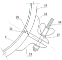
Fig. 7 is a schematic structural diagram of the combined three-piece sample making cylinder of the present invention.
Fig. 8 is a schematic top view of the structure of fig. 7.
Fig. 9 is a partially enlarged schematic view of fig. 8.
Fig. 10 is a schematic top view of the annular base plate.
Fig. 11 is a schematic top view of the base.
FIG. 12 is a schematic view of a disassembled structure of the connection relationship among the reaction frame, the spinning device, the base and the sample cylinder in the structure of FIG. 1.
Fig. 13 is a schematic structural view of the sample preparation after adding coarse-grained soil for the first time.
Fig. 14 is a schematic structural diagram of the sixth sampling after coarse-grained soil is added.
Shown in the figure: the test device comprises a base 1, an annular bottom plate 2, a water permeable plate 3, a rubber film 4, a sample preparation barrel 5, a rigid reaction column 6, a reaction cover plate 7, a round hole 8, a central screw hole 9, a thread 10, a handle 11, a spinning rod 12, a nut 13, a push head round cake 14, a central through hole 15, a long rod bolt 16, a water permeable hole 17, a sample cap 18, a plug 18-1, a plug 18-2, a plug column 19, an upper boss 20, a middle boss 21, a lower boss 21, a convex clamping groove 22, a screw clamping piece 23, a fastening bolt 24, an arc-shaped rigid template 25, a concave clamping groove 26, a fastening hole 27, a highest scale line 28, a lowest scale line 29 and a soil sample 30.
Detailed Description
Example 1:
referring to fig. 1-14, which are schematic structural views of an embodiment of the present invention, a spinning coarse-grained soil triaxial experiment sampler mainly includes a base 1, a reaction frame, a rubber membrane 4, a sample preparation cylinder 5, a spinning device, a porous plate 3, and a sample cap 18;
the base 1 comprises an upper layer of cylindrical bosses 19, a middle layer of cylindrical bosses 20 and a lower layer of cylindrical bosses 21, wherein the upper layer of cylindrical bosses, the middle layer of cylindrical bosses and the lower layer of cylindrical bosses are different in diameter; the reaction frame comprises an annular bottom plate 2, a rigid reaction column 6 and a reaction cover plate 7, the lower end of the rigid reaction column 6 is fixed on the annular bottom plate 2, a round hole 8 is formed in the reaction cover plate 7, threads are arranged at the upper end of the rigid reaction column 6, the upper end of the rigid reaction column 6 penetrates through the round hole 8 in the reaction cover plate 7 and is fixed with the reaction cover plate 7 through a nut 13, and a central screw hole 9 is formed in the middle of the reaction cover plate 7; the annular bottom plate 2 is provided with a central through hole 15, the annular bottom plate 2 is sleeved on an upper-layer boss 19 of the base 1 and is connected with a lower-layer boss 21 of the base 1 through a long-rod bolt 16.
The sample preparation cylinder 5 is a cylindrical body and is formed by combining three circular arc-shaped rigid templates 25, one side end of each circular arc-shaped rigid template 25 is provided with a convex clamping groove 22, the other side end of each circular arc-shaped rigid template is provided with a concave clamping groove 26 matched with the convex clamping groove, the three circular arc-shaped rigid templates 25 are combined together in an end-to-end connection mode to form the cylindrical body, through mutual embedding of the clamping grooves, each circular arc-shaped rigid template 25 is further provided with a screw clamping piece 23, the positions of the screw clamping pieces 23 on the two adjacent circular arc-shaped rigid templates 25 correspond to each other, each screw clamping piece 23 is provided with a fastening hole 27, and the adjacent circular arc.
The spinning device comprises a spinning rod 12, a handle 11 and a pushing head round cake 14, wherein the handle 11 is fixed at the upper end of the spinning rod 12, the pushing head round cake 14 is fixed at the lower end of the spinning rod 12, a thread 10 is arranged on the spinning rod 12, penetrates through a central screw hole 9 of the counter-force cover plate 7 and is in threaded connection with the counter-force cover plate 7, scale marks are further arranged on the spinning rod 12, the diameter of the pushing head round cake 14 is matched with the inner diameter of the sample preparation cylinder 5, and the pushing head round cake 14 can be inserted from the upper part of the sample preparation cylinder 5 and can move up and down;
the rubber membrane 4 is arranged on the periphery of the outer wall of an upper-layer boss 19 of the base 1 and extends upwards, the lower part of the sample preparation cylinder 5 is sleeved on the periphery of the outer wall of the rubber membrane 4 on the periphery of the upper-layer boss 19, the rubber membrane 4 is close to the inner wall of the sample preparation cylinder 5, and the annular bottom plate 2 of the reaction frame is sleeved on the outer wall of the lower part of the sample preparation cylinder 5; the inner diameter of the sample preparation cylinder 5 is matched with the outer diameter of the rubber membrane 4 sleeved on the periphery of the upper-layer boss 19, and the outer diameter of the sample preparation cylinder 5 is matched with the inner diameter of the annular bottom plate 2.
The water permeable plate 3 is provided with water permeable holes 17, is positioned in the sample preparation cylinder 5 and on the upper-layer boss 19, and the diameter of the water permeable plate is matched with that of the upper-layer boss 19; the structure of the sample cap 18 comprises a plug top 18-1 and a plug column 18-2, and the diameter of the plug column 18-2 is matched with the inner diameter of the sample preparation cylinder 5.
The scale marks carved on the spinning rod 12 are 6, and the highest scale mark 28 is located: when the highest scale mark 28 of the rotary pressing rod 12 is coincided with the upper edge of the central screw hole 9 of the counter force cover plate 7, the distance from the lower surface of the push head cake 14 to the top surface of the water permeable plate 3 is 1/6 equal to the height of the prepared soil sample 30; the lowest tick mark 29 is located: when the lowest scale mark 29 of the rotary pressing rod 12 is superposed with the upper edge of the central screw hole 9 of the counter force cover plate 7, the distance from the lower surface of the push head round cake 14 to the top surface of the water permeable plate 3 is equal to the height of the prefabricated soil sample 30; the other tick mark positions are the bisectors of the fifth between the highest tick mark 28 and the lowest tick mark 29.
The number of the rigid reaction columns 6 is four, threads are arranged on the tops of the rigid reaction columns 6, the four rigid reaction columns 6 are fixed with the reaction cover plate 7 through nuts 13, and the reaction cover plate 7 can be fixed on a horizontal plane within the adjustable range of the threads.
The three-piece type circular arc-shaped rigid template 25 of the sample preparation cylinder is combined, wherein the corresponding central angle of each circular arc-shaped rigid template 25 is 120 degrees, the screw clamping pieces 23 are arranged at the positions of the joint outer sides of the adjacent circular arc-shaped rigid templates 25 and the height 2/3 of the sample preparation cylinder 5, and the relative positions of the screw clamping pieces 23 are fixed by manually screwing the fastening bolts 24.
The height of the rubber membrane 4 is larger than that of the sample preparation cylinder 5.
The inner diameter of the sample preparation cylinder 5 is 206mm, and the height of the sample preparation cylinder 5 is 550 mm; the thickness of the rubber membrane 4 is 3mm, and the height is 580 mm; the length of the spinning rod 12 is 760 mm; the thickness of the push head round cake 14 is 10mm, and the diameter is 200 mm.
Claims (9)
1. A spinning type coarse-grained soil triaxial experiment sample preparation device is characterized by mainly comprising a base, a reaction frame, a rubber membrane, a sample preparation cylinder, a spinning device, a water permeable plate and a sample cap;
the base comprises an upper layer of cylindrical bosses, a middle layer of cylindrical bosses and a lower layer of cylindrical bosses, the cylindrical bosses have different diameters, the reaction frame comprises an annular bottom plate, a rigid reaction column and a reaction cover plate, the lower end of the rigid reaction column is fixed on the annular bottom plate, the reaction cover plate is provided with a round hole, the upper end of the rigid reaction column is provided with a thread, the upper end of the rigid reaction column penetrates through the round hole in the reaction cover plate and is fixed with the reaction cover plate by a nut, and the middle part of the reaction cover plate is provided; the annular bottom plate is provided with a central through hole, is sleeved on the upper-layer lug boss of the base and is connected with the lower-layer lug boss of the base through a long rod bolt;
the sample preparation cylinder is a cylindrical body and is formed by combining three circular arc-shaped rigid templates, one side end of each circular arc-shaped rigid template is provided with a convex clamping groove, the other side end of each circular arc-shaped rigid template is provided with a matched concave clamping groove, the three circular arc-shaped rigid templates are combined together in an end-to-end joint mode to form the cylindrical body, through mutual embedding of the clamping grooves, each circular arc-shaped rigid template is further provided with a screw rod clamping piece, the positions of the screw rod clamping pieces on the two adjacent circular arc-shaped rigid templates are corresponding, each screw rod clamping piece is provided with a fastening hole, and the adjacent circular arc-shaped rigid templates;
the spinning device comprises a spinning rod, a handle and a push head round cake, the handle is fixed at the upper end of the spinning rod, the push head round cake is fixed at the lower end of the spinning rod, threads are arranged on the spinning rod, the screw penetrates through a central screw hole of the counter-force cover plate and is in threaded connection with the counter-force cover plate, scale marks are further arranged on the spinning rod, the diameter of the push head round cake is matched with the inner diameter of the sample preparation cylinder, and the push head round cake can be inserted from the upper part of the sample preparation cylinder and moves up and down;
the rubber film is arranged on the outer wall of an upper-layer boss of the base in a circle and extends upwards, the lower part of the sample preparation barrel is sleeved on the outer wall of the rubber film on the periphery of the upper-layer boss in a circle, the rubber film is close to the inner wall of the sample preparation barrel, and the annular bottom plate of the reaction frame is sleeved on the outer wall of the lower part of the sample preparation barrel; the inner diameter of the sample preparation cylinder is matched with the outer diameter of a rubber film sleeved on the periphery of the upper-layer boss, and the outer diameter of the sample preparation cylinder is matched with the inner diameter of the annular bottom plate;
the water permeable plate is provided with water permeable holes, is positioned in the sample preparation cylinder and on the upper-layer boss, and the diameter of the water permeable plate is matched with that of the upper-layer boss; the structure of sample cap contains stopper top, stopper post, the diameter of stopper post and the internal diameter looks adaptation of system appearance section of thick bamboo, the stopper post is followed system appearance section of thick bamboo upper end mouth can be plugged in.
2. The spinning type coarse-grained soil triaxial test sampler according to claim 1, wherein the spinning rod is engraved with 6 scale marks, and the highest scale mark is located: when the highest scale mark of the rotary pressure rod is superposed with the upper edge of the central screw hole of the counter-force cover plate, the distance from the lower surface of the push head round cake to the top surface of the water permeable plate is equal to 1/6 of the height of the prefabricated soil sample; the positions of the lowest tick marks are: when the lowest scale mark of the spinning rod is superposed with the upper edge of the central screw hole of the counter-force cover plate, the distance from the lower surface of the push head round cake to the top surface of the water permeable plate is equal to the height of the prefabricated soil sample; the other tick mark positions are the bisectors of the fifth between the highest tick mark and the lowest tick mark.
3. The spinning type coarse-grained soil triaxial test sample preparation device as claimed in claim 1 or 2, characterized in that the number of the rigid reaction columns is four, the tops of the rigid reaction columns are provided with threads, and the four rigid reaction columns are fixed with the reaction cover plate through nuts, and the reaction cover plate can be fixed on a horizontal plane within the adjustable range of the threads.
4. The spinning type coarse-grained soil triaxial test sampler as claimed in claim 1 or 2, characterized in that three circular arc rigid templates combined into the sampling cylinder are provided, wherein each circular arc rigid template corresponds to a central angle of 120 degrees, the outer side of the joint of the adjacent circular arc rigid templates is provided with a screw clamping piece at the height 2/3 of the sampling cylinder, and the relative position of the screw clamping pieces is fixed by manually tightening a fastening bolt.
5. The spinning coarse-grained soil triaxial test sampler according to claim 3, characterized in that three circular arc rigid templates combined into the sampling cylinder are provided, wherein each circular arc rigid template corresponds to a central angle of 120 degrees, the outer side of the joint of the adjacent circular arc rigid templates is provided with a screw clamping piece at the height 2/3 of the sampling cylinder, and the relative position of the screw clamping piece is fixed by manually tightening a fastening bolt.
6. The spinning-type coarse-grained soil triaxial test sampler according to claim 1 or 2, characterized in that the height of the rubber membrane is greater than the height of the sampling cylinder.
7. The spinning coarse-grained soil triaxial test sampler according to claim 5, wherein the height of the rubber membrane is greater than the height of the sampler barrel.
8. The spinning coarse-grained soil triaxial test sampler according to claim 1 or 2, characterized in that the inner diameter of the sampling cylinder is 206mm, and the height of the sampling cylinder is 550 mm; the thickness of the rubber film is 3mm, and the height is 580 mm; the length of the spinning rod is 760 mm; the thickness of the round push head cake is 10mm, and the diameter is 200 mm.
9. The spinning coarse-grained soil triaxial test sampler according to claim 7, wherein the inner diameter of the sampling cylinder is 206mm, and the height of the sampling cylinder is 550 mm; the thickness of the rubber film is 3mm, and the height is 580 mm; the length of the spinning rod is 760 mm; the thickness of the round push head cake is 10mm, and the diameter is 200 mm.
Priority Applications (1)
| Application Number | Priority Date | Filing Date | Title |
|---|---|---|---|
| CN202020064226.9U CN211740831U (en) | 2020-01-13 | 2020-01-13 | Spinning type coarse-grained soil triaxial experiment sample preparation device |
Applications Claiming Priority (1)
| Application Number | Priority Date | Filing Date | Title |
|---|---|---|---|
| CN202020064226.9U CN211740831U (en) | 2020-01-13 | 2020-01-13 | Spinning type coarse-grained soil triaxial experiment sample preparation device |
Publications (1)
| Publication Number | Publication Date |
|---|---|
| CN211740831U true CN211740831U (en) | 2020-10-23 |
Family
ID=72882002
Family Applications (1)
| Application Number | Title | Priority Date | Filing Date |
|---|---|---|---|
| CN202020064226.9U Expired - Fee Related CN211740831U (en) | 2020-01-13 | 2020-01-13 | Spinning type coarse-grained soil triaxial experiment sample preparation device |
Country Status (1)
| Country | Link |
|---|---|
| CN (1) | CN211740831U (en) |
Cited By (2)
| Publication number | Priority date | Publication date | Assignee | Title |
|---|---|---|---|---|
| CN111103185A (en) * | 2020-01-13 | 2020-05-05 | 石河子大学 | Spinning type coarse-grained soil triaxial experiment sample preparation device and sample preparation method |
| CN114166601A (en) * | 2021-12-02 | 2022-03-11 | 浙江大学 | Bidirectional press-in type triaxial sample preparation device and method based on soil stress history |
-
2020
- 2020-01-13 CN CN202020064226.9U patent/CN211740831U/en not_active Expired - Fee Related
Cited By (4)
| Publication number | Priority date | Publication date | Assignee | Title |
|---|---|---|---|---|
| CN111103185A (en) * | 2020-01-13 | 2020-05-05 | 石河子大学 | Spinning type coarse-grained soil triaxial experiment sample preparation device and sample preparation method |
| CN111103185B (en) * | 2020-01-13 | 2023-11-21 | 石河子大学 | Spinning coarse-grained soil triaxial experiment sample preparation device and sample preparation method |
| CN114166601A (en) * | 2021-12-02 | 2022-03-11 | 浙江大学 | Bidirectional press-in type triaxial sample preparation device and method based on soil stress history |
| CN114166601B (en) * | 2021-12-02 | 2022-10-21 | 浙江大学 | Bidirectional press-in type triaxial sample preparation device and method based on soil stress history |
Similar Documents
| Publication | Publication Date | Title |
|---|---|---|
| CN111103185A (en) | Spinning type coarse-grained soil triaxial experiment sample preparation device and sample preparation method | |
| CN211740831U (en) | Spinning type coarse-grained soil triaxial experiment sample preparation device | |
| CN107817146B (en) | Dual-compression soil sample preparation device and sample preparation method | |
| CN203881595U (en) | Remolded soil sample builder | |
| CN109959773B (en) | Test device and method for reinforcing silt through demoulding microorganism grouting | |
| CN104913959A (en) | High-airtightness sample preparation device and sample preparation method thereof | |
| CN102914631A (en) | Testing device for measuring expansive force of soil sample in real time | |
| CN106644763B (en) | Earthen site anchoring slurry-matrix interface mechanical property test device and method | |
| CN106610353A (en) | Device used for preparing triaxial test samples via layer-compacting | |
| CN113155575A (en) | Coarse-grained soil triaxial sample preparation device with sample saturation and transfer functions and sample preparation method | |
| CN210037357U (en) | Hydraulic jack-based sample preparation device for remolded soil with different sizes | |
| CN114964956A (en) | Device for preparing triaxial sample by independently executing and compacting program and using method | |
| CN204959833U (en) | Indoor test device of miniature slip casting rubble steel -pipe pile | |
| CN104865158A (en) | Concrete mixture workability apparatus | |
| CN205049395U (en) | Utilize compaction in layers legal system to be equipped with device of triaxial test sample | |
| CN210375917U (en) | Triaxial remolded sample is preparation facilities fast in batches | |
| CN210690181U (en) | Novel geotechnical test sample preparation device | |
| CN205049453U (en) | Geosynthetic material permeates coefficient measurement appearance perpendicularly | |
| CN206638555U (en) | A kind of water permeability coefficient of water permeable brick test device simple to operate | |
| CN206670939U (en) | Building building cement sampling detecting device | |
| CN213517146U (en) | Concrete slump test fixing and leveling device | |
| CN206177682U (en) | A forming device for getting test of core sample impervious performance | |
| CN204758367U (en) | High leakproofness system appearance device | |
| CN114800795A (en) | Vertical combined die for preparing triaxial compression test sample and using method | |
| CN209802928U (en) | variable water head soil permeability coefficient measuring device |
Legal Events
| Date | Code | Title | Description |
|---|---|---|---|
| GR01 | Patent grant | ||
| GR01 | Patent grant | ||
| CF01 | Termination of patent right due to non-payment of annual fee | ||
| CF01 | Termination of patent right due to non-payment of annual fee |
Granted publication date: 20201023 |