CN211716614U - Internal circulation negative pressure material conveying structure of biomass stove - Google Patents
Internal circulation negative pressure material conveying structure of biomass stove Download PDFInfo
- Publication number
- CN211716614U CN211716614U CN202020299631.9U CN202020299631U CN211716614U CN 211716614 U CN211716614 U CN 211716614U CN 202020299631 U CN202020299631 U CN 202020299631U CN 211716614 U CN211716614 U CN 211716614U
- Authority
- CN
- China
- Prior art keywords
- conveying
- combustor
- biomass stove
- negative pressure
- water tank
- Prior art date
- Legal status (The legal status is an assumption and is not a legal conclusion. Google has not performed a legal analysis and makes no representation as to the accuracy of the status listed.)
- Active
Links
Images


Landscapes
- Solid-Fuel Combustion (AREA)
Abstract
The utility model provides a biomass stove inner loop negative pressure material conveying structure, including the biomass stove main part, the combustor is installed to the intracavity of biomass stove main part, material storehouse and air exhauster are installed respectively to both ends around the combustor, first conveying pipeline is installed to the inboard in material storehouse, spiral conveying pole is installed to the inboard of first conveying pipeline, just be equipped with the wind channel on the outer wall of combustor, the one end in wind channel is connected with the water tank, one side of water tank pass through the pipeline with the air intake of air exhauster links to each other, just it is equipped with a plurality of ventilation holes, and is a plurality of to crisscross on the inner wall of combustor the ventilation hole runs through in proper order the combustor with the wind channel, the second conveying pipeline is installed to the rear end of first conveying pipeline. The utility model discloses a first conveying pipeline, spiral conveying pole, combustor, second conveying pipeline, wind channel, ventilation hole, air exhauster and water tank have realized the automatic transport and the negative pressure circulation oxygen suppliment of material, have improved combustion effect.
Description
Technical Field
The utility model mainly relates to the technical field of biomass stoves, in particular to an internal circulation negative pressure material conveying structure of a biomass stove.
Background
The existing biomass stove can utilize biomass materials such as straws to burn, is good in combustion effect, free of black smoke and capable of reducing environmental pollution, but the biomass materials are inconvenient to add, easily block a conveying pipeline, not only are difficult to clean, but also use experience of people is reduced.
According to patent document application number 201620424751.0, a biomass stove is provided, including the furnace body shell, the inside bearing net that is provided with down of furnace body shell, the upside is provided with the bearing net, the furnace body shell is inside to fall into combustion chamber, row's ash chamber under the effect of bearing net down, be provided with the feed plate on combustion chamber one side, it arranges the flitch to be provided with on the ash chamber lateral wall to arrange, it corresponds to be provided with a plurality of inlet port on the furnace body shell lateral wall to arrange the ash chamber, the inside discharge tube that is provided with of combustion chamber, the discharge tube is connected with the adsorption pump through the gas-supply pipe, the adsorption pump is connected with the rose box, though enables the abundant burning of straw, has improved the utilization to the straw, but the joining of material is inconvenient. Therefore, it is necessary to develop a biomass stove internal circulation negative pressure material conveying structure, realize the automatic conveying of material, improve material combustion effect.
SUMMERY OF THE UTILITY MODEL
The utility model mainly provides a biomass stove internal circulation negative pressure material conveying structure for solve the technical problem who proposes among the above-mentioned background art.
The utility model provides a technical scheme that above-mentioned technical problem adopted does:
a biomass stove internal circulation negative pressure material conveying structure comprises a biomass stove main body, wherein a combustor is vertically installed in a cavity of the biomass stove main body, a material bin and an exhaust fan are respectively installed at the front end and the rear end of the combustor, a first conveying pipe is installed on the inner side of the material bin, a spiral conveying rod is installed on the inner side of the first conveying pipe, an air channel is fixedly wrapped on the outer wall of the combustor, a water tank is connected to one end, away from the combustor, of the air channel, one side, away from the air channel, of the water tank is connected with an air inlet of the exhaust fan through a pipeline, a plurality of ventilation holes are formed in the inner wall of the combustor in a staggered mode, and the ventilation holes sequentially and horizontally penetrate through the combustor and the air channel;
the rear end of the first conveying pipeline is provided with a second conveying pipeline in a penetrating mode, a discharge port of the second conveying pipeline is connected with the combustor, and a discharge port of the second conveying pipeline is located below a discharge port of the first conveying pipeline.
Further, the support frame is installed to the bottom of material storehouse, driving motor is installed to the bottom of support frame, driving motor's output shaft rotates through the shaft coupling and is connected with first gear, first gear is located the inboard of support frame, one side meshing of first gear is connected with the second gear, install at the top center department of second gear spiral material conveying pole, the bottom of spiral material conveying pole is run through the second gear extends to the interior bottom plate of support frame is through ball bearing and rotates the connection.
Furthermore, a disc is installed at the top of the supporting frame, and the top end of the spiral conveying rod sequentially penetrates through the disc, the material bin and the first conveying pipe and extends to the inner side of the first conveying pipe.
Further, vibrating motor is installed to one side of material storehouse, vibrating motor's output shaft rotates through the rotor and is connected with the vibrating arm, the vibrating arm is kept away from vibrating motor's one end runs through the material storehouse with first conveying pipeline extends to the inboard of first conveying pipeline, a plurality of vibrating vane are installed in the crisscross on the outer wall of vibrating arm.
Furthermore, one end of the air duct penetrates through the water tank and extends to the inner side of the water tank, and the water level of the water tank is higher than the air outlet of the air duct.
Furthermore, a feeding port is formed in one side, opposite to the second conveying pipe, of the first conveying pipe.
Furthermore, a cover plate is installed at the top end of the material bin.
Compared with the prior art, the beneficial effects of the utility model are that:
one of the two, the utility model discloses an automatic transport and negative pressure circulation oxygen suppliment of material, add the pot on the combustor, the confined air gets into the combustor, it rotates to drive the conveyor blade through pivoted spiral material conveying pole, the material moves along the conveyor blade of continuous rotation, because the discharge gate of second conveying pipeline is located the below of first conveying pipeline discharge gate, therefore the material sends into in the combustor through the second conveying pipeline that sets up to one side down, later draw out the air of water tank through air exhauster work, form the negative pressure in the water tank, the water tank is taken out the air in the combustor through the wind channel this moment, the air of outside gets into the combustor through wind channel and ventilation hole, the circulation of air has been realized, combustion effect has been improved;
and secondly, the utility model discloses have and prevent blockking up the effect, the material in the material storehouse passes through the pan feeding mouth and gets into first conveying pipeline, through vibrating motor work, drives the vibrating arm vibration, drives the vibration of vibration blade through the vibrating arm, through the continuous vibration of vibrating arm and vibration blade, prevents that the pan feeding mouth from being blockked up by the material, has improved the conveying efficiency of material.
The present invention will be explained in detail with reference to the drawings and specific embodiments.
Drawings
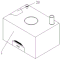
Fig. 1 is a schematic view of the overall structure of the present invention;
FIG. 2 is a schematic view of the internal structure of the biomass stove body of the present invention;
fig. 3 is a schematic structural view of the burner and the material bin of the present invention;
FIG. 4 is a schematic structural view of a rotary mechanism of the screw feeding rod of the present invention;
fig. 5 is a sectional view of the material bin structure of the present invention;
fig. 6 is an enlarged view of the area a in fig. 3.
In the figure: 1. a biomass stove main body; 2. a material bin; 21. a first feed delivery pipe; 211. a feeding port; 22. a support frame; 23. a drive motor; 24. a first gear; 25. a screw feed rod; 251. a disc; 26. a second gear; 27. a second delivery pipe; 28. a cover plate; 3. a burner; 31. an air duct; 32. a vent hole; 4. a water tank; 5. a vibrating rod; 51. vibrating the blade; 52. a vibration motor; 6. an exhaust fan.
Detailed Description
In order to facilitate understanding of the present invention, the present invention will be described more fully with reference to the accompanying drawings, in which several embodiments of the present invention are shown, but the present invention can be implemented in different forms, and is not limited to the embodiments described in the text, but rather, these embodiments are provided to make the disclosure of the present invention more thorough and comprehensive.
It will be understood that when an element is referred to as being "secured to" another element, it can be directly on the other element or intervening elements may be present, and when an element is referred to as being "connected" to another element, it can be directly connected to the other element or intervening elements may also be present, as the terms "vertical", "horizontal", "left", "right" and the like are used herein for descriptive purposes only.
Unless defined otherwise, all technical and scientific terms used herein have the same meaning as commonly understood by one of ordinary skill in the art to which this invention belongs, and the use of the term knowledge in the specification of the present invention is for the purpose of describing particular embodiments and is not intended to limit the present invention, and the term "and/or" as used herein includes any and all combinations of one or more of the associated listed items.
Please refer to fig. 1-6 heavily, an internal circulation negative pressure material conveying structure of a biomass stove comprises a biomass stove main body 1, a burner 3 is vertically installed in a cavity of the biomass stove main body 1, a material bin 2 and an exhaust fan 6 are respectively installed at the front end and the rear end of the burner 3, a first material conveying pipe 21 is installed at the inner side of the material bin 2, a spiral material conveying rod 25 is installed at the inner side of the first material conveying pipe 21, an air duct 31 is fixedly wrapped on the outer wall of the burner 3, one end of the air duct 31 far away from the burner 3 is connected with a water tank 4, one side of the water tank 4 far away from the air duct 31 is connected with an air inlet of the exhaust fan 6 through a pipeline, a plurality of vent holes 32 are staggered on the inner wall of the burner 3, the vent holes 32 sequentially and horizontally penetrate through the burner 3 and the air duct 31, a second material conveying pipe 27 is installed at the rear end of the first material conveying pipe 21, the discharge gate of second conveying pipeline 27 with combustor 3 links to each other, the discharge gate of second conveying pipeline 27 is located the below of first conveying pipeline 21 discharge gate, support frame 22 is installed to the bottom of material storehouse 2, driving motor 23 is installed to the bottom of support frame 22, driving motor 23's output shaft passes through the shaft coupling and rotates and be connected with first gear 24, first gear 24 is located the inboard of support frame 22, one side meshing of first gear 24 is connected with second gear 26, install at the top center department of second gear 26 spiral material conveying pole 25, run through the bottom of spiral material conveying pole 25 second gear 26 extends to the interior bottom plate of support frame 22 is through ball bearing and is the rotation connection, disc 251 is installed at the top of support frame 22, just run through in proper order on the top of spiral material conveying pole 25 disc 251, The material bin 2 and the first conveying pipeline 21 extend to the inner side of the first conveying pipeline 21, one end of the air channel 31 penetrates through the water tank 4 and extends to the inner side of the water tank 4, the water level of the water tank 4 is higher than an air outlet of the air channel 31, and a cover plate 28 is installed at the top end of the material bin 2. In this embodiment, through driving motor 23 work, the first gear 24 of drive rotates, because first gear 24 is connected with the meshing of second gear 26, consequently, drive second gear 26 and rotate, and then drive spiral conveying pole 25 and rotate, spiral conveying pole 25 drives conveyor blade and rotates, and the water level of water tank 4 is higher than the air outlet in wind channel 31, has the cooling effect, covers material storehouse 2 through apron 28, prevents that the dust from piling up the combustion effect that reduces the material on the material.
Please refer to fig. 3 and fig. 5, a vibration motor 52 is installed at one side of the material bin 2, an output shaft of the vibration motor 52 is rotatably connected with a vibration rod 5 through a rotor, one end of the vibration rod 5, which is far away from the vibration motor 52, penetrates through the material bin 2 and the first material conveying pipe 21 and extends to the inner side of the first material conveying pipe 21, a plurality of vibration blades 51 are installed on the outer wall of the vibration rod 5 in a staggered manner, and a feeding port 211 is arranged at one side of the first material conveying pipe 21, which is opposite to the second material conveying pipe 27. In this embodiment, the material in the material bin 2 enters the first conveying pipeline 21 through the feeding port 211, and through the work of the vibration motor 52, the vibration rod 5 is driven to vibrate, the vibration blades 51 are driven to vibrate through the vibration rod 5, and through the continuous vibration of the vibration rod 5 and the vibration blades 51, the feeding port 211 is prevented from being blocked by the material, and the conveying efficiency of the material is improved.
The utility model discloses a concrete operation as follows:
firstly, a pot is added on a combustor 3, closed air enters the combustor 3, materials in a material bin 2 enter a first material conveying pipe 21 through a feeding port 211, a driving motor 23 works to drive a first gear 24 to rotate, the first gear 24 is meshed with a second gear 26 to drive the second gear 26 to rotate, a spiral material conveying rod 25 is further driven to rotate, the spiral material conveying rod 25 drives a conveying blade to rotate, the materials move along the continuously rotating conveying blade, a discharge port of a second material conveying pipe 27 is positioned below a discharge port of the first material conveying pipe 21, the materials are conveyed into the combustor 3 through the second material conveying pipe 27 which is obliquely arranged downwards, then air in a water tank 4 is extracted through a suction fan 6, negative pressure is formed in the water tank 4, at the moment, the water tank 4 extracts the air in the combustor 3 through an air duct 31, and outside air enters the combustor 3 through the air duct 31 and a vent 32, realized the circulation of air, improved the combustion effect, worked through vibrating motor 52, driven the vibration of vibrating arm 5, driven vibration blade 51 vibration through vibrating arm 5, through vibrating arm 5 and vibration blade 51's continuous vibration, prevented that pan feeding mouth 211 from being blockked up by the material, improved the conveying efficiency of material.
The present invention has been described above with reference to the accompanying drawings, and it is obvious that the present invention is not limited by the above-mentioned manner, if the method and the technical solution of the present invention are adopted, the present invention can be directly applied to other occasions without substantial improvement, and the present invention is within the protection scope of the present invention.
Claims (7)
1. The utility model provides a biomass stove inner loop negative pressure material conveying structure, includes biomass stove main part (1), its characterized in that, combustor (3) are installed perpendicularly to the intracavity of biomass stove main part (1), material storehouse (2) and air exhauster (6) are installed respectively to both ends around combustor (3), first conveying pipeline (21) are installed to the inboard in material storehouse (2), spiral conveying pole (25) are installed to the inboard of first conveying pipeline (21), just fixed parcel has wind channel (31) on the outer wall of combustor (3), the one end that combustor (3) were kept away from in wind channel (31) is connected with water tank (4), one side that wind channel (31) were kept away from in water tank (4) is passed through the pipeline and is linked to each other with the air intake of air exhauster (6), just crisscross being equipped with a plurality of ventilation holes (32) on the inner wall of combustor (3), the plurality of air vents (32) sequentially and horizontally penetrate through the burner (3) and the air duct (31);
the rear end of first conveying pipeline (21) runs through and installs second conveying pipeline (27), the discharge gate of second conveying pipeline (27) with combustor (3) link to each other, the discharge gate of second conveying pipeline (27) is located the below of first conveying pipeline (21) discharge gate.
2. The internal circulation negative-pressure material conveying structure of the biomass stove according to claim 1, characterized in that a support frame (22) is installed at the bottom of the material bin (2), a driving motor (23) is installed at the bottom of the support frame (22), an output shaft of the driving motor (23) is rotatably connected with a first gear (24) through a coupling, the first gear (24) is located on the inner side of the support frame (22), a second gear (26) is meshed and connected with one side of the first gear (24), the spiral material conveying rod (25) is installed at the center of the top end of the second gear (26), and the bottom end of the spiral material conveying rod (25) penetrates through the second gear (26) and extends to the inner bottom plate of the support frame (22) and is rotatably connected through a ball bearing.
3. The internal circulation negative pressure material conveying structure of the biomass stove according to claim 2, wherein a disc (251) is installed on the top of the supporting frame (22), and the top end of the spiral conveying rod (25) sequentially penetrates through the disc (251), the material bin (2) and the first conveying pipe (21) and extends to the inner side of the first conveying pipe (21).
4. The internal circulation negative pressure material conveying structure of the biomass stove according to claim 1, wherein a vibration motor (52) is installed at one side of the material bin (2), an output shaft of the vibration motor (52) is rotatably connected with a vibration rod (5) through a rotor, one end of the vibration rod (5) far away from the vibration motor (52) penetrates through the material bin (2) and the first conveying pipe (21) and extends to the inner side of the first conveying pipe (21), and a plurality of vibration blades (51) are installed on the outer wall of the vibration rod (5) in a staggered mode.
5. The internal circulation negative pressure material conveying structure of the biomass stove according to claim 1, wherein one end of the air duct (31) extends through the water tank (4) to the inner side of the water tank, and the water level of the water tank (4) is higher than the air outlet of the air duct (31).
6. The internal circulation negative pressure material conveying structure of the biomass stove as claimed in claim 1, wherein a feeding port (211) is provided on the first material conveying pipe (21) at a side opposite to the second material conveying pipe (27).
7. The internal circulation negative pressure material conveying structure of the biomass stove according to claim 1, wherein a cover plate (28) is installed at the top end of the material bin (2).
Priority Applications (1)
| Application Number | Priority Date | Filing Date | Title |
|---|---|---|---|
| CN202020299631.9U CN211716614U (en) | 2020-03-12 | 2020-03-12 | Internal circulation negative pressure material conveying structure of biomass stove |
Applications Claiming Priority (1)
| Application Number | Priority Date | Filing Date | Title |
|---|---|---|---|
| CN202020299631.9U CN211716614U (en) | 2020-03-12 | 2020-03-12 | Internal circulation negative pressure material conveying structure of biomass stove |
Publications (1)
| Publication Number | Publication Date |
|---|---|
| CN211716614U true CN211716614U (en) | 2020-10-20 |
Family
ID=73396974
Family Applications (1)
| Application Number | Title | Priority Date | Filing Date |
|---|---|---|---|
| CN202020299631.9U Active CN211716614U (en) | 2020-03-12 | 2020-03-12 | Internal circulation negative pressure material conveying structure of biomass stove |
Country Status (1)
| Country | Link |
|---|---|
| CN (1) | CN211716614U (en) |
-
2020
- 2020-03-12 CN CN202020299631.9U patent/CN211716614U/en active Active
Similar Documents
| Publication | Publication Date | Title |
|---|---|---|
| CN211716614U (en) | Internal circulation negative pressure material conveying structure of biomass stove | |
| CN210625198U (en) | Bamboo shoots drying device | |
| CN109404887B (en) | Combustion furnace for biological combustion | |
| CN207094609U (en) | A kind of secondary combustion of biomass fuel boiler | |
| CN211600780U (en) | Biomass energy heating stove | |
| CN212504762U (en) | Clean energy conversion device for wood sundries | |
| CN213207933U (en) | Biological particle heater | |
| CN112143524A (en) | Blast furnace circulating oxygen supply device and use method thereof | |
| CN206890503U (en) | A kind of direct-drive type novel combustion engine | |
| CN212746570U (en) | Wood-burning particle fireplace for large-capacity high-efficiency castings | |
| CN216582998U (en) | Carbon powder conveying device | |
| CN219889540U (en) | Biomass combustion furnace | |
| CN220669501U (en) | Induced air type waste heat recovery firewood stove | |
| CN218337414U (en) | Adjustable water curtain air deflector | |
| CN220976895U (en) | Biomass gasifier for recycling and gasifying flue gas | |
| CN220413271U (en) | High-temperature biomass gasification furnace | |
| CN219363556U (en) | Energy-saving gasification furnace | |
| CN216591726U (en) | Biomass straw burner with waste heat recovery function | |
| CN216814141U (en) | Chain grate gasification device using whole bundle of wrapped crop straw as fuel | |
| CN217330695U (en) | Organic halogen combustion furnace | |
| CN110617699A (en) | Biomass particle furnace for drying and heating grains | |
| CN113432115B (en) | Modular biomass gasification burner | |
| CN211831990U (en) | Raw material crushing device for production of crop straw biomass fuel | |
| CN219199149U (en) | Biomass combustion furnace with circulating air port | |
| CN214891321U (en) | Oxygen supply circulating device of biomass combustion furnace |
Legal Events
| Date | Code | Title | Description |
|---|---|---|---|
| GR01 | Patent grant | ||
| GR01 | Patent grant | ||
| TR01 | Transfer of patent right |
Effective date of registration: 20220907 Address after: No. 15, Mengxiu Logistics Park, Shanba Town, Hangjinhou Banner, Bayannaoer City, Inner Mongolia Autonomous Region, 015000 Patentee after: Inner Mongolia jingyuantai Environmental Protection Technology Co.,Ltd. Address before: 015000 store 15, mengxiu logistics park, Hangjinhou banner, Bayannur City, Inner Mongolia Autonomous Region Patentee before: Inner Mongolia jingfengtai agriculture and forestry science and Technology Energy Co.,Ltd. |
|
| TR01 | Transfer of patent right |