CN211714180U - Assembled concrete frame structure - Google Patents
Assembled concrete frame structure Download PDFInfo
- Publication number
- CN211714180U CN211714180U CN201921868556.7U CN201921868556U CN211714180U CN 211714180 U CN211714180 U CN 211714180U CN 201921868556 U CN201921868556 U CN 201921868556U CN 211714180 U CN211714180 U CN 211714180U
- Authority
- CN
- China
- Prior art keywords
- precast concrete
- column
- frame structure
- precast
- friction
- Prior art date
- Legal status (The legal status is an assumption and is not a legal conclusion. Google has not performed a legal analysis and makes no representation as to the accuracy of the status listed.)
- Active
Links
Images


Landscapes
- Joining Of Building Structures In Genera (AREA)
Abstract
The utility model particularly discloses an assembled concrete frame structure, including precast concrete post, precast concrete superposed beam and coincide floor, precast concrete superposed beam connects perpendicularly in one side of precast concrete post, coincide floor installs in coincide roof beam top; and pouring joint bonding materials are filled in beam column joints between the precast concrete columns and the precast concrete superposed beams, friction parts are arranged on the precast concrete columns and the precast concrete superposed beams, and the friction parts are in contact with the pouring joint bonding materials and are used for resisting shearing force. This frame construction has utilized the friction portion that sets up on roof beam, the post to replace original shear reinforcement, satisfying under the prerequisite of structure shear strength, not only improved the convenience of node construction, practiced thrift the cost to a certain extent moreover. In addition, the contact surface of the beam column is not provided with a rough surface, which is beneficial to environmental protection and industrial production.
Description
Technical Field
The utility model relates to a construction technical field especially relates to an assembled concrete frame structure.
Background
At present, a hybrid-connected post-tensioned prestressed fabricated concrete frame structure system has good self-resetting capability and excellent earthquake resistance, and has been accepted by standards of the united states, new zealand and europe. However, from the perspective of engineering construction, the system is still relatively complex in structure, low in construction efficiency and relatively high in manufacturing cost compared with the traditional assembled system.
On the basis of a hybrid connection prestress assembly type concrete frame structure system, a compression joint method of a frame beam column is provided, steel bars on the lower portion of a beam end do not stretch into the column structurally, and installation efficiency is greatly improved. The beam-column contact surface of the node construction generally needs to be provided with a rough surface to ensure the transmission of the pressure contact friction force of the contact surface. The production process suitable for the rough surface mainly comprises the following steps: chiseling, napping, exposing aggregate and washing with water. Dust flies in the process of the chiseling process, pollutes the environment and wastes time and labor; the roughness of the napping process is difficult to control, and the labor cost is high; the exposed aggregate agent and water washing process is complex, a special water washing station needs to be set, the waste water can be discharged after being treated, and cement paste has great pollution to the factory environment and is not beneficial to industrial production.
Therefore, a beam column joint structure which is convenient to produce, simple in structure, efficient to install, safe and environment-friendly needs to be developed.
SUMMERY OF THE UTILITY MODEL
The utility model provides an assembly type concrete frame structure of convenient production, simple structure, high-efficient, the safety ring of installation.
The technical problem to be solved is that: the existing frame beam column compression joint method has the disadvantages of complicated contact surface rough treatment process, environmental pollution and difficulty in controlling cost and quality.
In order to solve the technical problems, the invention adopts the following technical scheme:
an assembled concrete frame structure comprises a precast concrete column, a precast concrete superposed beam and a superposed floor slab, wherein the precast concrete superposed beam is vertically connected to one side of the precast concrete column, and the superposed floor slab is arranged above the superposed beam; and pouring joint bonding materials are filled in beam column joints between the precast concrete columns and the precast concrete superposed beams, friction parts are arranged on the precast concrete columns and the precast concrete superposed beams, and the friction parts are in contact with the pouring joint bonding materials and are used for resisting shearing force.
Further, the friction part is a groove, and a pattern or a bump for increasing the friction coefficient is arranged on the inner concave surface of the groove.
Further, the depth of the groove is not less than 30mm, and the outer edge of the groove has a slope extending to the bottom of the groove, the angle of the slope being not more than 30 °.
Furthermore, a plurality of grooves are sequentially arranged on one side, close to the crack pouring bonding material, of the precast concrete column in the height direction, and the whole width of each groove is the same as the width of the vertical section of the precast concrete composite beam.
Further, the cross section of the groove is in an isosceles trapezoid shape.
Further, the friction part is a bump, and a pattern or a bump for increasing the friction coefficient is arranged on the outer convex surface of the bump.
Furthermore, the precast concrete superposed beam comprises a precast beam at the lower part and a beam post-pouring layer at the upper part, the friction part is arranged on the precast beam, and the bottom of the friction part is provided with a beam prestressed rib pre-embedded corrugated pipe along the length direction of the precast beam; a column prestressed rib embedded corrugated pipe is arranged at the bottom of the friction part of the precast concrete column along the direction vertical to the length of the precast concrete column;
the post prestressed reinforcement pre-buried corrugated pipe corresponds to the beam prestressed reinforcement pre-buried corrugated pipe, and the post prestressed reinforcement bundle sequentially penetrates through the beam prestressed reinforcement pre-buried corrugated pipe and the post prestressed reinforcement pre-buried corrugated pipe and is tensioned and fastened through the prestressed reinforcement outer anchor head.
Furthermore, the frame structure further comprises bending-resistant energy-consuming steel bars, one ends of the bending-resistant energy-consuming steel bars extend into the precast concrete columns and are connected with the anchoring steel bars in the columns through mechanical connecting joints, and the other ends of the bending-resistant energy-consuming steel bars are poured in the beam post-pouring layer.
Further, the width of a beam column joint between the precast concrete superposed beam and the precast concrete column is 10-50 mm.
Furthermore, the crack pouring bonding material is one or more of rapid hardening cement-based grouting material with the compressive strength of more than 45MPa, fiber rapid hardening cement-based grouting material or polymer mortar.
Compared with the prior art, the technical scheme provided by the utility model, following beneficial effect has:
the utility model discloses an all set up friction portion on precast concrete superposed beam and precast concrete post, through the cementation of fissures material of filling between friction portion and the beam column contacts each other to produce the friction, utilize produced shearing force between the beam column is resisted to the friction, thereby increased beam column seam crossing's shear strength, and then improved overall structure's anti ability of collapsing in succession. Meanwhile, the frame structure utilizes the friction part to replace the original shear steel bar, so that the convenience of node construction is improved, and the cost is saved to a certain extent. In addition, the contact surface of the beam column is not provided with a rough surface, which is beneficial to environmental protection and industrial production.
Drawings
Fig. 1 is a three-dimensional structural view of an assembled concrete framework structure;
FIG. 2 is a top view of an assembled concrete frame structure;
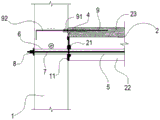
FIG. 3 is a schematic cross-sectional view A-A of FIG. 2;
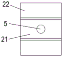
FIG. 4 is a schematic structural view of a friction part of the precast concrete composite beam;
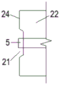
FIG. 5 is a schematic view of the structure of FIG. 4 at another angle;
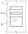
FIG. 6 is a schematic view showing a structure of a friction part of a precast concrete column;
fig. 7 is a schematic view of the structure at another angle of fig. 6.
Reference numerals:
1. prefabricating a concrete column; 11. a first groove; 12. a side wall;
2. prefabricating a concrete superposed beam; 21. a second groove; 22. prefabricating a beam; 23. post-beam casting; 24. an end face;
3. overlapping the floor slabs; 31. prefabricating a slab; 32. post-pouring a layer on the plate;
4. pouring a joint bonding material;
5. pre-burying a corrugated pipe by using beam prestressed ribs;
6. pre-burying a corrugated pipe by using a column prestressed tendon;
7. post-tensioned prestressed tendons;
8. an outer anchor head of the prestressed tendon;
9. bending-resistant energy-consuming reinforcing steel bars; 91. a mechanical connection joint; 92. and (5) anchoring steel bars in the columns.
Detailed Description
To make the objects, features and advantages of the present invention more obvious and understandable, the embodiments of the present invention are described clearly and completely with reference to the accompanying drawings in the embodiments of the present invention, and obviously, the described embodiments are only some embodiments of the present invention, not all embodiments. Based on the embodiments in the present invention, all other embodiments obtained by the skilled in the art without creative work belong to the protection scope of the present invention.
In the description herein, references to the description of the term "one embodiment," "some embodiments," "an example," "a specific example," or "some examples," etc., mean that a particular feature, structure, material, or characteristic described in connection with the embodiment or example is included in at least one embodiment or example of the invention. Furthermore, the particular features, structures, materials, or characteristics described may be combined in any suitable manner in any one or more embodiments or examples. Furthermore, various embodiments or examples and features of different embodiments or examples described in this specification can be combined and combined by one skilled in the art without contradiction.
Furthermore, the terms "first", "second" and "first" are used for descriptive purposes only and are not to be construed as indicating or implying relative importance or implicitly indicating the number of technical features indicated. Thus, a feature defined as "first" or "second" may explicitly or implicitly include at least one such feature. In the description of the present invention, "a plurality" means two or more unless specifically limited otherwise.
Please refer to fig. 1 to 3, which are embodiments of the present invention provide a fabricated concrete frame structure, which includes a precast concrete column 1, a precast concrete composite beam 2 and a composite floor slab 3, wherein the precast concrete composite beam 2 is vertically connected to one side of the precast concrete column 1, and the composite floor slab 3 is installed above the composite beam 2.
The width of a beam-column joint between the precast concrete composite beam 2 and the precast concrete column 1 is 10-50mm, and a crack pouring bonding material 4 is filled in the beam-column joint between the precast concrete column 1 and the precast concrete composite beam 2, so that the beam and the column are bonded together. The crack pouring bonding material 4 is one or more of rapid-hardening cement-based grouting material with the compressive strength of more than 45MPa, fiber rapid-hardening cement-based grouting material or polymer mortar, and can be selected according to actual needs during specific use.
The precast concrete column 1 and the precast concrete superposed beam 2 are respectively provided with a friction part, the friction parts are in contact with the crack pouring bonding material 4, and friction force is generated by mutual friction between the friction parts and the crack pouring bonding material 4, so that shearing force generated between the beam and the column is resisted.
Referring to fig. 4 to 7, in the present embodiment, the friction portion is a groove. Specifically, a first groove 11 is formed in one side, close to the crack pouring bonding material 4, of the precast concrete column 1, and a second groove 21 is formed in one side, close to the crack pouring bonding material 4, of the precast concrete superposed beam 2. The inner concave surfaces of the first groove 11 and the second groove 21 are provided with patterns or salient points, and the patterns can be formed by pressing a pattern steel plate and used for increasing the friction coefficient of the inner concave surfaces of the grooves, so that the friction force between the friction part and the crack pouring bonding material 4 is increased. It should be noted that, in this embodiment, only the friction portion is taken as a groove for illustration, in other embodiments, the friction portion may also be a bump, and a pattern or a bump for increasing the friction coefficient is provided on an outer convex surface of the bump.
Referring to fig. 3, the precast concrete composite beam 2 includes a precast beam 22 at a lower portion and a post-cast beam layer 23 at an upper portion, the second groove 21 is disposed on the precast beam 22, and a pre-embedded beam prestressed rib corrugated pipe 5 is disposed at the bottom of the second groove 21 along the length direction of the precast beam 22. The bottom of the first groove 11 of the precast concrete column 1 is provided with a column prestressed tendon embedded corrugated pipe 6 along the direction perpendicular to the length of the precast concrete column 1. In this embodiment, the bottom of the first groove 11 refers to the horizontal inner wall of the first groove 11, and the bottom of the second groove 21 refers to the horizontal inner wall of the second groove 21.
The column prestressed tendon embedded corrugated pipe 6 corresponds to the beam prestressed tendon embedded corrugated pipe 5, the port of the column prestressed tendon embedded corrugated pipe 6 is flush with the side wall 12 of the precast concrete column 1, and the port of the beam prestressed tendon embedded corrugated pipe 5 is flush with the end face 24 of the precast concrete composite beam 2. The post-tensioned prestressed reinforcement bundle 7 sequentially passes through the beam prestressed reinforcement pre-embedded corrugated pipe 5 and the column prestressed reinforcement pre-embedded corrugated pipe 6, and the beam and the column are tensioned and fastened through the prestressed reinforcement outer anchor head 8 so as to fix the relative positions of the beam and the column.
Meanwhile, in this embodiment, the frame structure further includes anti-bending energy-consuming steel bars 9, one end of each anti-bending energy-consuming steel bar 9 extends into the precast concrete column 1 and is connected with an in-column anchoring steel bar 92 through a mechanical connecting joint 91, the other end of each anti-bending energy-consuming steel bar 9 is poured into the post-beam casting layer 23, and the anti-bending energy-consuming steel bars 9 are located above the post-tensioned prestressed steel bar bundles 7.
During specific construction, referring to fig. 1, the laminated floor slab 3 comprises a precast slab 31 and a slab post-cast layer 32, the slab post-cast layer 32 and the beam post-cast layer 23 are integrally cast, and the bending-resistant energy-consuming steel bars 9 are cast therein to form a whole, so that the structural integrity is improved, the floors are guaranteed to have good waterproof performance, the post-cast steel bars are convenient to arrange, and the construction difficulty is greatly reduced. Meanwhile, the post-tensioned prestressed reinforcement bundles 7 are combined with the bending-resistant energy-consuming reinforcements 9 above the post-tensioned prestressed reinforcement bundles to connect the beam columns to form a complete stress system, so that the energy consumption of the structure is effectively improved, and the seismic resistance and the continuous collapse resistance of the structure are enhanced.
Preferably, in the above embodiment, the depth of the first groove 11 and the second groove 21 is not less than 30mm, and the outer edges of the first groove 11 and the second groove 21 each have a slope extending to the bottom of the groove, and the angle of the slope is not more than 30 degrees. The cross sections of the first groove 11 and the second groove 21 are both in an isosceles trapezoid shape, and in other embodiments, the cross sections of the first groove 11 and the second groove 21 may also be in a common trapezoid shape.
Preferably, in the above embodiment, a plurality of first grooves 11 are sequentially arranged on one side of the precast concrete column 1 close to the joint grouting bonding material 4 along the height direction, and the overall width of the plurality of first grooves 11 is the same as the vertical section width of the precast concrete composite beam 2. Through increasing the quantity of first recess 11 to enlarge first recess 11 and cementation of fissures bonding material 4's area of contact to form unevenness's structure on the whole, thereby be favorable to increasing the frictional force between precast concrete post 1 and the cementation of fissures bonding material 4, improve shear strength. Of course, the precast beams 22 of the precast concrete composite beam 2 may also be provided with a plurality of second grooves 21 in the height direction.
To sum up, the embodiment of the utility model provides an assembled concrete frame structure has not only strengthened the anti-seismic performance of structure and the ability of anti collapsing in succession, utilizes filling joint bonding material 4 of filling between friction portion and roof beam, the post to contact each other moreover, produces the friction, utilizes the produced shearing force between roof beam, the post is resisted to the friction to increased the shear strength of beam column seam crossing, and then improved overall structure's anti ability of collapsing in succession. Meanwhile, the frame structure utilizes the friction part to replace the original shear steel bar, so that the convenience of node construction is improved, and the cost is saved to a certain extent. In addition, the contact surface of the beam column is not provided with a rough surface, which is beneficial to environmental protection and industrial production.
The above description is only for the specific embodiments of the present invention, but the protection scope of the present invention is not limited thereto, and any person skilled in the art can easily think of the changes or substitutions within the technical scope of the present invention, and all should be covered within the protection scope of the present invention. Therefore, the protection scope of the present invention shall be subject to the protection scope of the claims.
Claims (9)
1. An assembled concrete frame structure comprises a precast concrete column (1), a precast concrete superposed beam (2) and a superposed floor slab (3), and is characterized in that the precast concrete superposed beam (2) is vertically connected to one side of the precast concrete column (1), and the superposed floor slab (3) is arranged above the superposed beam; pouring bonding materials (4) are filled in beam column joints between the precast concrete columns (1) and the precast concrete superposed beams (2), friction parts are arranged on the precast concrete columns (1) and the precast concrete superposed beams (2) and are in contact with the pouring bonding materials (4), each precast concrete superposed beam (2) comprises a precast beam (22) at the lower part and a post-beam pouring layer (23) at the upper part, the friction parts are arranged on the precast beams (22), and beam prestressed rib pre-embedded corrugated pipes (5) are arranged at the bottoms of the friction parts along the length direction of the precast beams (22); a column prestressed rib pre-embedded corrugated pipe (6) is arranged at the bottom of the friction part of the precast concrete column (1) along the direction vertical to the length of the precast concrete column (1); the post-tensioned prestressed reinforcement bundle (7) sequentially penetrates through the beam prestressed reinforcement pre-embedded corrugated pipe (5) and the column prestressed reinforcement pre-embedded corrugated pipe (6), and the beam column is tensioned and fastened through the prestressed reinforcement outer anchor head (8), so that static friction force along the tangential direction of the beam end is generated, and the post-tensioned prestressed reinforcement bundle is used for resisting shearing force.
2. A fabricated concrete frame structure according to claim 1, wherein the friction portion is a groove having a pattern or a protrusion for increasing a friction coefficient on an inner concave surface thereof.
3. A fabricated concrete frame structure according to claim 2, wherein the depth of the groove is not less than 30mm, and the outer edge of the groove has a slope extending to the bottom of the groove, the angle of the slope being not more than 30 °.
4. The fabricated concrete frame structure according to claim 2, wherein a plurality of grooves are sequentially formed in the height direction on one side of the precast concrete column (1) close to the cementation material (4), and the overall width of the plurality of grooves is the same as the width of the vertical section of the precast concrete composite beam (2).
5. An assembled concrete frame structure according to claim 2, wherein the cross-section of the groove is in the shape of an isosceles trapezoid.
6. A fabricated concrete frame structure according to claim 1, wherein the friction portion is a projection having a pattern or a bump for increasing a friction coefficient on an outer convex surface thereof.
7. An assembled concrete frame structure according to claim 1, further comprising bend dissipating reinforcement (9), one end of the bend dissipating reinforcement (9) extending into the column (1) of precast concrete and being connected to the in-column anchoring reinforcement (92) by means of a mechanical connection joint (91), the other end of the bend dissipating reinforcement (9) being cast in the post-cast beam layer (23).
8. A fabricated concrete frame structure according to any one of claims 1-7, wherein the width of the beam-column joint between the precast concrete composite beam (2) and the precast concrete column (1) is 10-50 mm.
9. An assembled concrete frame structure according to any one of claims 1 to 7, characterised in that the joint grouting bonding material (4) is one of a rapid hardening cement based grouting material, a fibre rapid hardening cement based grouting material or a polymer mortar having a compressive strength of more than 45 MPa.
Priority Applications (1)
| Application Number | Priority Date | Filing Date | Title |
|---|---|---|---|
| CN201921868556.7U CN211714180U (en) | 2019-11-01 | 2019-11-01 | Assembled concrete frame structure |
Applications Claiming Priority (1)
| Application Number | Priority Date | Filing Date | Title |
|---|---|---|---|
| CN201921868556.7U CN211714180U (en) | 2019-11-01 | 2019-11-01 | Assembled concrete frame structure |
Publications (1)
| Publication Number | Publication Date |
|---|---|
| CN211714180U true CN211714180U (en) | 2020-10-20 |
Family
ID=72814420
Family Applications (1)
| Application Number | Title | Priority Date | Filing Date |
|---|---|---|---|
| CN201921868556.7U Active CN211714180U (en) | 2019-11-01 | 2019-11-01 | Assembled concrete frame structure |
Country Status (1)
| Country | Link |
|---|---|
| CN (1) | CN211714180U (en) |
Cited By (1)
| Publication number | Priority date | Publication date | Assignee | Title |
|---|---|---|---|---|
| CN113463755A (en) * | 2021-06-25 | 2021-10-01 | 无锡市亨利富建设发展有限公司 | Concrete frame column anti-seismic structure and construction method thereof |
-
2019
- 2019-11-01 CN CN201921868556.7U patent/CN211714180U/en active Active
Cited By (1)
| Publication number | Priority date | Publication date | Assignee | Title |
|---|---|---|---|---|
| CN113463755A (en) * | 2021-06-25 | 2021-10-01 | 无锡市亨利富建设发展有限公司 | Concrete frame column anti-seismic structure and construction method thereof |
Similar Documents
| Publication | Publication Date | Title |
|---|---|---|
| CN103388357B (en) | Shatter-proof, prefabricated steel tube shear Temperature Variation In Buildings of Mixed Structures thing | |
| CN108086488B (en) | Assembled frame shear structure wall staggered connection structure and assembling method | |
| CN108179809A (en) | The connection method of assembled steel tendon concrete frame structure component | |
| CN103195259B (en) | Method for reinforcing concrete structure by foam concrete prefabricated slab | |
| CN115045181A (en) | Socket joint type node connection method and structure for prefabricated pier column and bearing platform in middle and high intensity region | |
| CN110644662A (en) | Prefabricated flat slab composite slab based on stress and splitting method thereof | |
| CN215166634U (en) | Assembly type building wallboard connecting structure | |
| CN215106121U (en) | One-way superimposed sheet piece department joint construction | |
| CN211714180U (en) | Assembled concrete frame structure | |
| CN111749364B (en) | Assembled composite wall based on C-shaped steel and construction method thereof | |
| KR101625995B1 (en) | Precast deck and slab having the same | |
| CN105040855B (en) | Prefabricated shear wall welded end plate and horizontal section steel combined connection apparatus | |
| CN218643645U (en) | Full-assembly type reinforced concrete floor connected by steel-concrete combined structure | |
| CN216338993U (en) | Longitudinal joint for steel-UHPC (ultra high performance concrete) assembled pi-shaped combination beam | |
| CN114635503A (en) | Fair-faced concrete wall flexibly connected with concrete frame column and construction method | |
| CN113123506B (en) | Prefabricated die-removal-free steel bar truss floor bearing plate based on uhpc and using method | |
| CN214831925U (en) | ECC material-based bridge wet joint structure with template | |
| CN211286164U (en) | Self-compaction regeneration block concrete superimposed shear wall | |
| CN210134346U (en) | Ultrahigh-performance bridge deck plate structure | |
| CN112227580A (en) | Steel pipe truss prestressed hollow superimposed sheet | |
| CN208039457U (en) | Novel fabricated reinforced concrete frame structure | |
| CN113374171A (en) | Recycled block concrete prefabricated assembled ring beam structure and construction method thereof | |
| CN112982692A (en) | One-way superimposed sheet joint connecting structure and construction method | |
| CN203475599U (en) | Shock-proof prefabricated building of steel tube shearing wall composite structure | |
| CN112853916A (en) | Assembled waffle bridge panel combined box girder structure and construction method thereof |
Legal Events
| Date | Code | Title | Description |
|---|---|---|---|
| GR01 | Patent grant | ||
| GR01 | Patent grant |