CN211705096U - A rotatable nursing bed - Google Patents
A rotatable nursing bed Download PDFInfo
- Publication number
- CN211705096U CN211705096U CN201921579808.4U CN201921579808U CN211705096U CN 211705096 U CN211705096 U CN 211705096U CN 201921579808 U CN201921579808 U CN 201921579808U CN 211705096 U CN211705096 U CN 211705096U
- Authority
- CN
- China
- Prior art keywords
- plate
- movably connected
- fixedly connected
- connecting rod
- screw rod
- Prior art date
- Legal status (The legal status is an assumption and is not a legal conclusion. Google has not performed a legal analysis and makes no representation as to the accuracy of the status listed.)
- Expired - Fee Related
Links
Images


Landscapes
- Invalid Beds And Related Equipment (AREA)
Abstract
本实用新型属于医疗技术领域,一种可旋转的护理床,包括底板,所述底板的上表面活动连接有连杆,连杆中部固定连接有螺母,所述螺母内壁螺纹连接有丝杆,所述丝杆的另一端设置有电机,所述电机的输出轴上活动穿设有轴承,所述电机的输出轴与丝杆的一端固定连接,所述连杆的另一端活动连接有支撑板,所述支撑板的一侧设置有开关;本实用新型,通过设置连杆,丝杆和电机的配合,可实现护理床的整体高度自由可调,方便适应病人的需求,通过设置转板,使整个床板可旋转,并且上床板通过手动丝杆15可以调节抬升角度,方便病人起身,下床板可以向下折叠,同时配合可自由调节的高度,给病人下床提供方便。
The utility model belongs to the technical field of medical treatment, and a rotatable nursing bed comprises a bottom plate, a connecting rod is movably connected to the upper surface of the bottom plate, a nut is fixedly connected to the middle of the connecting rod, and a screw rod is threadedly connected to the inner wall of the nut, so that the The other end of the screw rod is provided with a motor, the output shaft of the motor is movably provided with a bearing, the output shaft of the motor is fixedly connected with one end of the screw rod, and the other end of the connecting rod is movably connected with a support plate, One side of the support plate is provided with a switch; in the utility model, the overall height of the nursing bed can be freely adjusted by arranging the connecting rod, the cooperation of the screw rod and the motor, which is convenient to meet the needs of the patient. The whole bed board can be rotated, and the upper bed board can be adjusted by the manual screw rod 15 to lift the angle, which is convenient for the patient to get up.
Description
技术领域technical field
本实用新型属于医疗技术领域,具体涉及一种可旋转的护理床。The utility model belongs to the field of medical technology, in particular to a rotatable nursing bed.
背景技术Background technique
随着国内老龄化的加重,国内对多功能护理床的需求也起义增加,护理床,就是以床为本体,延伸出多种多样功能的,对病人起到一定保护和方便病人使用的床,目前,过内的护理床大致可可分为电动护理床和手动护理床,电动护理床以电为能源,驱动各种用电设备达到实现功能的目的,但大多价格昂贵,手动护理床虽价格拥有一定的优势,但是功能性和方便性不足,而且目前的护理床大多不能旋转,给病人下床带来一定的困难。With the aggravation of domestic aging, the domestic demand for multi-functional nursing beds has also increased. At present, nursing beds can be roughly divided into electric nursing beds and manual nursing beds. Electric nursing beds use electricity as energy to drive various electrical equipment to achieve the purpose of achieving functions, but most of them are expensive. Although the price of manual nursing beds has It has certain advantages, but the function and convenience are insufficient, and most of the current nursing beds cannot be rotated, which brings certain difficulties to patients getting out of bed.
实用新型内容Utility model content
为解决上述背景技术中提出的问题。本实用新型提供了一种可旋转的护理床,具有可自由升降高度、床板可旋转方便病人下床特点。In order to solve the problems raised in the above background art. The utility model provides a rotatable nursing bed, which has the characteristics that the height can be freely raised and lowered, and the bed board can be rotated to facilitate the patient getting out of bed.
为实现上述目的,本实用新型提供如下技术方案:一种可旋转的护理床,包括底板,所述底板的上表面活动连接有连杆,连杆中部固定连接有螺母,所述螺母内壁螺纹连接有丝杆,所述丝杆的另一端设置有电机,所述电机的输出轴上活动穿设有轴承,所述电机的输出轴与丝杆的一端固定连接,所述连杆的另一端活动连接有支撑板,所述支撑板的一侧设置有开关,所述支撑板的上表面活动连接有转板,所述转板的上端活动连接有上床板,所述转板的下端活动连接有下床板,所述转板的中部固定连接有支撑架,所述支撑架的内部开设螺纹通孔,螺纹通孔内螺纹连接有手动丝杆,所述手动丝杆的一端固定连接有挡板,且挡板的顶部与上板床的底部搭接,所述手动丝杆另一端固定连接有手柄。In order to achieve the above purpose, the present invention provides the following technical solutions: a rotatable nursing bed, comprising a bottom plate, a connecting rod is movably connected to the upper surface of the bottom plate, a nut is fixedly connected to the middle of the connecting rod, and the inner wall of the nut is threadedly connected There is a screw rod, the other end of the screw rod is provided with a motor, the output shaft of the motor is movably penetrated with a bearing, the output shaft of the motor is fixedly connected with one end of the screw rod, and the other end of the connecting rod is movable A support plate is connected, one side of the support plate is provided with a switch, the upper surface of the support plate is movably connected with a turning plate, the upper end of the turning plate is movably connected with an upper bed plate, and the lower end of the turning plate is movably connected with a A support frame is fixedly connected to the middle of the turning plate, a threaded through hole is provided in the inside of the support frame, a manual screw rod is threadedly connected in the threaded through hole, and a baffle plate is fixedly connected to one end of the manual screw rod, And the top of the baffle is overlapped with the bottom of the upper bed, and the other end of the manual screw rod is fixedly connected with a handle.
优选的,所述连杆的数量为两个,所述连杆的两端分别与底板和支撑板活动连接,所述连杆的中部活动连接成可折叠结构。Preferably, the number of the connecting rod is two, the two ends of the connecting rod are respectively movably connected with the bottom plate and the support plate, and the middle part of the connecting rod is movably connected to form a foldable structure.
优选的,所述底板的下表面固定连接有滚轮,所述滚轮的数量为四个,且所述滚轮均匀分布在底板的四角。Preferably, rollers are fixedly connected to the lower surface of the bottom plate, the number of the rollers is four, and the rollers are evenly distributed on the four corners of the bottom plate.
优选的,所述上床板和下床板活动连接在转板上,所述转板可绕轴心旋转。Preferably, the upper bed board and the lower bed board are movably connected to a rotating plate, and the rotating plate can rotate around the axis.
优选的,所述上床板的表面活动连接有半圆板,所述上床板可向上折叠,所述下床板可向下折叠。Preferably, a semicircular plate is movably connected to the surface of the upper bed board, the upper bed board can be folded upward, and the lower bed board can be folded downward.
优选的,所述上床板、下床板和转板的两侧均固定连接有挡板。Preferably, baffles are fixedly connected to both sides of the upper bed board, the lower bed board and the turning board.
与现有技术相比,本实用新型的有益效果是:Compared with the prior art, the beneficial effects of the present utility model are:
本实用新型,通过设置连杆、丝杆和电机的配合,可实现护理床的整体高度自由可调,方便适应病人的需求,通过设置转板,使整个床板可旋转,并且上床板通过手动丝杆可以调节抬升角度,方便病人起身,下床板可以向下折叠,同时配合可自由调节的高度,给病人下床提供方便,通过设置半圆板,为病人的头部护理提供方便。In the utility model, the overall height of the nursing bed can be freely adjusted by arranging the cooperation of the connecting rod, the screw rod and the motor, which is convenient to meet the needs of the patient. The rod can adjust the lifting angle, which is convenient for the patient to get up. The lower bed board can be folded down, and at the same time, it is convenient for the patient to get out of bed with the freely adjustable height.
附图说明Description of drawings
附图用来提供对本实用新型的进一步理解,并且构成说明书的一部分,与本实用新型的实施例一起用于解释本实用新型,并不构成对本实用新型的限制。在附图中:The accompanying drawings are used to provide a further understanding of the present invention, and constitute a part of the specification, and are used to explain the present invention together with the embodiments of the present invention, and do not constitute a limitation to the present invention. In the attached image:
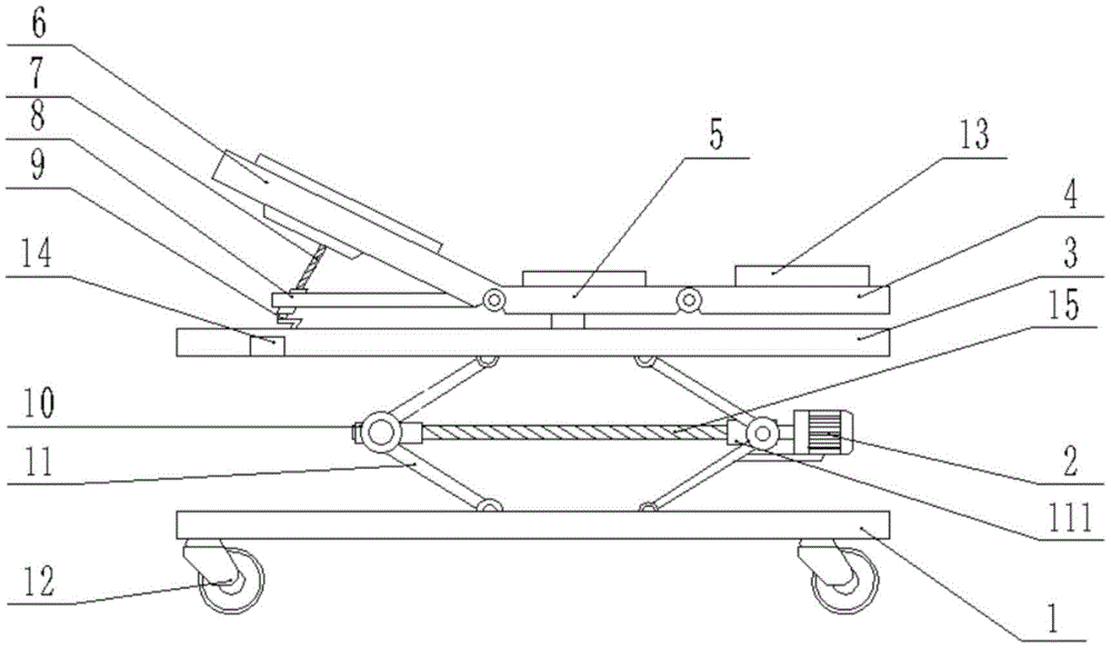
图1为本实用新型的主视结构示意图;Fig. 1 is the front view structure schematic diagram of the utility model;
图2为本实用新型中的立体结构示意图;Fig. 2 is the three-dimensional structure schematic diagram in the utility model;
图中:1、底板;2、电机;3、支撑板;4、下床板;5、转板;6、上床板;61、半圆板;7、手动丝杆15;8、支撑架;9、手柄;10、螺母;11、连杆;111、轴承;12、滚轮;13、挡板;14、开关;15、丝杆。In the figure: 1. Bottom plate; 2. Motor; 3. Support plate; 4. Lower bed plate; 5. Turning plate; 6. Upper bed plate; 61, Semicircular plate; Handle; 10, nut; 11, connecting rod; 111, bearing; 12, roller; 13, baffle; 14, switch; 15, screw.
具体实施方式Detailed ways
下面将结合本实用新型实施例中的附图,对本实用新型实施例中的技术方案进行清楚、完整地描述,显然,所描述的实施例仅仅是本实用新型一部分实施例,而不是全部的实施例。基于本实用新型中的实施例,本领域普通技术人员在没有做出创造性劳动前提下所获得的所有其他实施例,都属于本实用新型保护的范围。The technical solutions in the embodiments of the present utility model will be clearly and completely described below with reference to the accompanying drawings in the embodiments of the present utility model. Obviously, the described embodiments are only a part of the embodiments of the present utility model, rather than all the implementations. example. Based on the embodiments of the present invention, all other embodiments obtained by those of ordinary skill in the art without creative work fall within the protection scope of the present invention.
实施例Example
请参阅图1-2,本实用新型提供以下技术方案:一种可旋转的护理床,包括底板1,所述底板1的上表面活动连接有连杆11,连杆11中部固定连接有螺母10,所述螺母10内壁螺纹连接有丝杆15,丝杆15在没有外力的情况下可以实现轴向运动的自锁,防止护理床突然坠落,提高安全性,所述丝杆15的另一端设置有电机2,所述电机2的输出轴上活动穿设有轴承111,所述电机2的输出轴与丝杆15的一端固定连接,通过设置电机2,能够减少人力的使用,降低护理人员的劳动强度,方便使用,所述连杆11的另一端活动连接有支撑板3,所述支撑板3的一侧设置有开关14,所述支撑板3的上表面活动连接有转板5,所述转板5的上端活动连接有上床板6,所述转板5的下端活动连接有下床板4,所述转板5的中部固定连接有支撑架8,所述支撑架8的内部开设螺纹通孔,螺纹通孔内螺纹连接有手动丝杆7,所述手动丝杆7的一端固定连接有挡板,且挡板的顶部与上板床6的底部搭接,所述手动丝杆7另一端固定连接有手柄9。1-2, the present invention provides the following technical solutions: a rotatable nursing bed, comprising a
具体的,所述连杆11的数量为两个,所述连杆11的两端分别与底板1和支撑板3活动连接,所述连杆11的中部活动连接成可折叠结构。Specifically, the number of the connecting
具体的,所述底板1的下表面固定连接有滚轮12,所述滚轮12的数量为四个,且所述滚轮12均匀分布在底板1的四角,设置滚轮12,方便医护人员在紧急情况下转移病人,方便救治。Specifically, the lower surface of the
具体的,所述上床板6和下床板4活动连接在转板5上,所述转板5可绕轴心旋转。Specifically, the
具体的,所述上床板6的表面活动连接有半圆板61,使用时可以将半圆板61拿掉,方便护理,所述上床板6可向上折叠,所述下床板4可向下折叠,可以给病人一个舒适的角度。Specifically, a
具体的,所述上床板6、下床板4和转板5的两侧均固定连接有挡板13,设置挡板13,防止病人无意识的从护理床上跌落,提高安全性。Specifically,
本实用新型的工作原理及使用流程:本实用新型使用时,根据需要,按动开关14,使电机2工作,带动丝杆15运动,丝杆15牵动连杆11运动,将护理床的高度调节至合理的高度,方便病人上床,需要时,可旋动手柄9使上床板6抬升一定的角度,给病人提供一个舒适的角度,上床板6设置有半圆板61,当病人头部需要护理时,将半圆板61拿掉即可方便护理人员使用,当病人需要下床时,旋动手柄9,使上床板6升高,然后推动床板,利用转板5使整个床板旋转,然后放下下床板4,同时使护理床的高度调节至合适高度,方便病人下床。The working principle and use process of the utility model: when the utility model is used, according to the needs, press the
最后应说明的是:以上所述仅为本实用新型的优选实施例而已,并不用于限制本实用新型,尽管参照前述实施例对本实用新型进行了详细的说明,对于本领域的技术人员来说,其依然可以对前述各实施例所记载的技术方案进行修改,或者对其中部分技术特征进行等同替换。凡在本实用新型的精神和原则之内,所作的任何修改、等同替换、改进等,均应包含在本实用新型的保护范围之内。Finally, it should be noted that the above are only the preferred embodiments of the present invention, and are not intended to limit the present invention. , it is still possible to modify the technical solutions described in the foregoing embodiments, or perform equivalent replacements to some of the technical features. Any modification, equivalent replacement, improvement, etc. made within the spirit and principle of the present invention shall be included in the protection scope of the present invention.
Claims (6)
Priority Applications (1)
| Application Number | Priority Date | Filing Date | Title |
|---|---|---|---|
| CN201921579808.4U CN211705096U (en) | 2019-09-23 | 2019-09-23 | A rotatable nursing bed |
Applications Claiming Priority (1)
| Application Number | Priority Date | Filing Date | Title |
|---|---|---|---|
| CN201921579808.4U CN211705096U (en) | 2019-09-23 | 2019-09-23 | A rotatable nursing bed |
Publications (1)
| Publication Number | Publication Date |
|---|---|
| CN211705096U true CN211705096U (en) | 2020-10-20 |
Family
ID=72812679
Family Applications (1)
| Application Number | Title | Priority Date | Filing Date |
|---|---|---|---|
| CN201921579808.4U Expired - Fee Related CN211705096U (en) | 2019-09-23 | 2019-09-23 | A rotatable nursing bed |
Country Status (1)
| Country | Link |
|---|---|
| CN (1) | CN211705096U (en) |
Cited By (3)
| Publication number | Priority date | Publication date | Assignee | Title |
|---|---|---|---|---|
| CN112932837A (en) * | 2021-02-05 | 2021-06-11 | 青州市中医院 | Lower limb postoperative care device capable of being adjusted in multiple directions and assisting in massaging |
| CN113397870A (en) * | 2021-06-04 | 2021-09-17 | 郑州大学第一附属医院 | Nursing bed with auxiliary getting-off function |
| CN114176916A (en) * | 2022-01-10 | 2022-03-15 | 吉林大学第一医院 | Multifunctional nursing trolley for cadre ward |
-
2019
- 2019-09-23 CN CN201921579808.4U patent/CN211705096U/en not_active Expired - Fee Related
Cited By (4)
| Publication number | Priority date | Publication date | Assignee | Title |
|---|---|---|---|---|
| CN112932837A (en) * | 2021-02-05 | 2021-06-11 | 青州市中医院 | Lower limb postoperative care device capable of being adjusted in multiple directions and assisting in massaging |
| CN112932837B (en) * | 2021-02-05 | 2022-04-29 | 青州市中医院 | Lower limb postoperative care device capable of being adjusted in multiple directions and assisting in massaging |
| CN113397870A (en) * | 2021-06-04 | 2021-09-17 | 郑州大学第一附属医院 | Nursing bed with auxiliary getting-off function |
| CN114176916A (en) * | 2022-01-10 | 2022-03-15 | 吉林大学第一医院 | Multifunctional nursing trolley for cadre ward |
Similar Documents
| Publication | Publication Date | Title |
|---|---|---|
| CN201414896Y (en) | A medical movable electric lift bed | |
| CN211271854U (en) | Medical leg support frame | |
| CN220495159U (en) | Assisted turning bed | |
| CN211460903U (en) | A kind of multifunctional hospital bed for surgical intensive care unit | |
| CN207845078U (en) | A kind of power engineering repair lifting platform convenient for lifting | |
| CN212037561U (en) | Examining bed for radiology department | |
| CN213250546U (en) | But height-adjusting's nursing is filled up | |
| CN204814534U (en) | Medical bed for nursing care | |
| CN211986147U (en) | Multifunctional examining bed | |
| CN211912047U (en) | Smart Folding Rotary Lifting Bed | |
| CN221866515U (en) | Auxiliary supporting instrument | |
| CN216417592U (en) | Telescopic quilt supporting frame | |
| CN113893102A (en) | Medical care bed with supplementary function of changing dressings | |
| CN221785809U (en) | Electric adjustable bed frame | |
| CN212997139U (en) | An elderly care turning device | |
| CN221013714U (en) | Nursing equipment with monitor | |
| CN211934652U (en) | Lower limb inflating and heightening device for old people with blood diseases | |
| CN111904776A (en) | Physiotherapy bed for endocrinology department | |
| CN218943753U (en) | Comprehensive nursing auxiliary mobile supporting equipment | |
| CN221932392U (en) | A multifunctional turning nursing bed with protective function | |
| CN221654880U (en) | Nursing bed for assisting turning over | |
| CN211962392U (en) | Environment-friendly energy-saving postoperative auxiliary wheelchair for surgery | |
| CN216358640U (en) | Wheelchair pedal mechanism capable of automatically lifting and adjusting | |
| CN219354531U (en) | Sectional type height-adjustable's traditional chinese medical science massage bed | |
| CN214343037U (en) | Clinical care is with supplementary ware of getting up |
Legal Events
| Date | Code | Title | Description |
|---|---|---|---|
| GR01 | Patent grant | ||
| GR01 | Patent grant | ||
| CF01 | Termination of patent right due to non-payment of annual fee |
Granted publication date: 20201020 Termination date: 20210923 |
|
| CF01 | Termination of patent right due to non-payment of annual fee |