CN211683034U - A rubbing crusher for handling plastic film - Google Patents
A rubbing crusher for handling plastic film Download PDFInfo
- Publication number
- CN211683034U CN211683034U CN201922062005.8U CN201922062005U CN211683034U CN 211683034 U CN211683034 U CN 211683034U CN 201922062005 U CN201922062005 U CN 201922062005U CN 211683034 U CN211683034 U CN 211683034U
- Authority
- CN
- China
- Prior art keywords
- fixed
- box
- plastic film
- crushing
- crushing box
- Prior art date
- Legal status (The legal status is an assumption and is not a legal conclusion. Google has not performed a legal analysis and makes no representation as to the accuracy of the status listed.)
- Active
Links
Images


Classifications
-
- Y—GENERAL TAGGING OF NEW TECHNOLOGICAL DEVELOPMENTS; GENERAL TAGGING OF CROSS-SECTIONAL TECHNOLOGIES SPANNING OVER SEVERAL SECTIONS OF THE IPC; TECHNICAL SUBJECTS COVERED BY FORMER USPC CROSS-REFERENCE ART COLLECTIONS [XRACs] AND DIGESTS
- Y02—TECHNOLOGIES OR APPLICATIONS FOR MITIGATION OR ADAPTATION AGAINST CLIMATE CHANGE
- Y02W—CLIMATE CHANGE MITIGATION TECHNOLOGIES RELATED TO WASTEWATER TREATMENT OR WASTE MANAGEMENT
- Y02W30/00—Technologies for solid waste management
- Y02W30/50—Reuse, recycling or recovery technologies
- Y02W30/52—Mechanical processing of waste for the recovery of materials, e.g. crushing, shredding, separation or disassembly
-
- Y—GENERAL TAGGING OF NEW TECHNOLOGICAL DEVELOPMENTS; GENERAL TAGGING OF CROSS-SECTIONAL TECHNOLOGIES SPANNING OVER SEVERAL SECTIONS OF THE IPC; TECHNICAL SUBJECTS COVERED BY FORMER USPC CROSS-REFERENCE ART COLLECTIONS [XRACs] AND DIGESTS
- Y02—TECHNOLOGIES OR APPLICATIONS FOR MITIGATION OR ADAPTATION AGAINST CLIMATE CHANGE
- Y02W—CLIMATE CHANGE MITIGATION TECHNOLOGIES RELATED TO WASTEWATER TREATMENT OR WASTE MANAGEMENT
- Y02W30/00—Technologies for solid waste management
- Y02W30/50—Reuse, recycling or recovery technologies
- Y02W30/62—Plastics recycling; Rubber recycling
Landscapes
- Crushing And Pulverization Processes (AREA)
Abstract
The utility model relates to the technical field of plastic films, and discloses a grinder for processing plastic films, which comprises a grinding box, wherein a feed hopper is welded and fixed on the upper surface of the grinding box, the bottom end of the feed hopper is communicated with the inside of the grinding box, supporting legs are welded and fixed at four corners of the lower surface of the grinding box, a discharge hopper is welded and fixed on the lower surface of the grinding box, and the top of the discharge hopper is communicated with the inside of the grinding box; in the in-process that uses, when needs take out the crushing roller of inside and clear up, can dismantle two baffles on the crushing case, then through pressing down the fixture block, can press the fixture block into the inside of recess, outwards stimulate simultaneously and smash the roller to can take out crushing roller from the crushing case, and then make things convenient for operating personnel to clear up crushing roller, compare in current rubbing crusher, this rubbing crusher makes things convenient for operating personnel to take out crushing roller and clears up more.
Description
Technical Field
The utility model relates to a plastic film handles technical field, specifically is a rubbing crusher for handling plastic film.
Background
The plastic film is a film made of polyvinyl chloride, polyethylene, polypropylene, polystyrene and other resins, is used for packaging and is used as a film coating layer, and is widely applied to the fields of food, medicine, chemical engineering and the like, wherein the proportion of the plastic film in food packaging is the largest, such as beverage packaging, quick-frozen food packaging, steamed food packaging, fast food packaging and the like, the products bring great convenience to the life of people, the plastic film can generate waste films with quality which does not meet the requirements in the production and processing processes, and the films are directly used by an extruder or an injection molding machine after being crushed by a plastic film crusher.
When current plastic film rubbing crusher is smashing plastic film, because plastic film has certain toughness, consequently remain easily on crushing roller, and crushing roller among the current rubbing crusher is fixed mounting in the inside of rubbing crusher generally, inconvenient operating personnel takes out crushing roller from the rubbing crusher and clears up, and the opening on the feeder hopper on the current rubbing crusher generally directly exposes outside, when not using, the higher foreign matter of external hardness enters into the inside of rubbing crusher from the opening on the feeder hopper easily, thereby influence the work of rubbing crusher easily.
SUMMERY OF THE UTILITY MODEL
Technical problem to be solved
The utility model provides a not enough to prior art, the utility model provides a rubbing crusher for handling plastic film has solved the crushing roller among the current plastic grinder and has generally been fixed mounting in the inside of rubbing crusher, and inconvenient operating personnel takes out the crushing roller from the rubbing crusher and clears up, and current rubbing crusher when not using, and the higher foreign matter of external hardness enters into the inside of rubbing crusher from the opening on the feeder hopper easily to influence the problem of rubbing crusher's work easily.
(II) technical scheme
In order to achieve the above object, the utility model provides a following technical scheme: a pulverizer for processing plastic films comprises a pulverizing box, wherein a feed hopper is fixedly welded on the upper surface of the pulverizing box, the bottom end of the feed hopper is communicated with the inside of the pulverizing box, supporting legs are fixedly welded on four corners of the lower surface of the pulverizing box, a discharge hopper is fixedly welded on the lower surface of the pulverizing box, the top of the discharge hopper is communicated with the inside of the pulverizing box, connecting blocks are symmetrically and rotatably connected to the two sides of the inner surface of the pulverizing box in a front-back symmetrical mode, the connecting blocks are of a U-shaped structure, clamping holes are formed in the front surface and the rear surface of the inside of the connecting blocks, pulverizing rollers are symmetrically arranged in the front-back direction of the inside of the pulverizing box, shaft levers are fixedly welded at the centers of the two sides of the pulverizing rollers, the shaft levers are clamped in the connecting blocks, grooves are symmetrically formed in the outer surfaces of the shaft levers, and extension springs are fixed, one end of the telescopic spring is fixed with a clamping block, the clamping block is located outside the groove, the clamping block penetrates through the clamping hole, one side of the crushing box is fixed with a gear box, one side of the gear box is fixed with a motor through screws, a driving gear is connected to the inside of the gear box in a rotating mode, the inside of the gear box is located behind the driving gear and is connected with a driven gear in a rotating mode, the driving gear is meshed with the driven gear to be connected, an output shaft of the motor is fixedly connected with a middle shaft of the driving gear, the middle shaft of the driving gear is fixedly connected with one side of the connecting block in front of the left side, and the middle shaft of the driven gear is fixedly connected with one side of the connecting block in.
Preferably, one side of the clamping block, which is far away from the telescopic spring, is of an arc-shaped structure, and the clamping block is elastically connected with the shaft rod through the telescopic spring.
Preferably, smash the case and be front surface and rear surface open-ended cavity cuboid structure, just the front surface and the rear surface of smashing the case all are fixed with the baffle through the screw.
Preferably, the upper surface of the feeding hopper is rotatably connected with a cover plate, and the length and the width of the cover plate are greater than or equal to those of the upper surface of the feeding hopper.
Preferably, four the bottom of supporting leg all is fixed with through the screw and removes the wheel, four it is self-locking universal wheel to remove the wheel.
Preferably, a moving trolley is arranged between the four supporting legs below the discharge hopper, and a handle is welded and fixed to one side of the moving trolley.
(III) advantageous effects
The utility model provides a rubbing crusher for handling plastic film possesses following beneficial effect:
(1) the utility model discloses at the in-process that uses, when needs take out inside crushing roller and clear up, can dismantle two baffles on the crushing case get off, then through pressing down the fixture block, can press the inside of going into the recess with the fixture block, outwards stimulate simultaneously crushing roller to can take out crushing roller from the crushing case, and then make things convenient for operating personnel to clear up crushing roller, compare in current rubbing crusher, this rubbing crusher makes things convenient for operating personnel to take out crushing roller to clear up more.
(2) The utility model discloses rotate at the upper surface of feeder hopper and connect the apron, when rubbing crusher does not use, can rotate the apron to can make the upper surface of apron and feeder hopper laminate mutually, and then can shelter from the import of feeder hopper, avoid when not using, the harder foreign matter in the external world enters into rubbing crusher's inside, thereby influences the condition of rubbing crusher's work.
Drawings
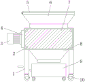
Fig. 1 is a schematic structural view of the present invention;
FIG. 2 is a schematic view of the top view of the inner structure of the crushing box of the present invention;
fig. 3 is an enlarged schematic structural diagram of a in fig. 2 of the present invention.
In the figure: 1. supporting legs; 2. a crushing box; 3. a motor; 4. a gear box; 5. a cover plate; 6. a feed hopper; 7. a baffle plate; 8. a discharge hopper; 9. moving the trolley; 10. a moving wheel; 11. a driving gear; 12. a driven gear; 13. a crushing roller; 14. a shaft lever; 15. connecting blocks; 16. a clamping block; 17. a clamping hole; 18. a groove; 19. a telescoping spring.
Detailed Description
The technical solutions in the embodiments of the present invention will be described clearly and completely with reference to the accompanying drawings in the embodiments of the present invention, and it is obvious that the described embodiments are only some embodiments of the present invention, not all embodiments. Based on the embodiments in the present invention, all other embodiments obtained by a person skilled in the art without creative work belong to the protection scope of the present invention.
As shown in fig. 1-3, the utility model provides a technical solution: a pulverizer for processing plastic films comprises a pulverizing box 2, a feed hopper 6 is fixedly welded on the upper surface of the pulverizing box 2, the bottom end of the feed hopper 6 is communicated with the inside of the pulverizing box 2, supporting legs 1 are fixedly welded on four corners of the lower surface of the pulverizing box 2, a discharge hopper 8 is fixedly welded on the lower surface of the pulverizing box 2, the top of the discharge hopper 8 is communicated with the inside of the pulverizing box 2, connecting blocks 15 are symmetrically and rotationally connected with the front and back of the two sides of the inner surface of the pulverizing box 2, the connecting blocks 15 are U-shaped structures, clamping holes 17 are respectively arranged on the front and back surfaces of the inside of the connecting blocks 15, pulverizing rollers 13 are symmetrically arranged on the front and back of the inside of the pulverizing box 2, shaft levers 14 are fixedly welded on the centers of the two sides of the pulverizing rollers 13, the shaft levers 14 are clamped in the inside of the connecting blocks 15, grooves 18 are symmetrically arranged on the outer surfaces of, one end of a telescopic spring 19 is fixed with a clamping block 16, the clamping block 16 is positioned outside a groove 18, the clamping block 16 penetrates through a clamping hole 17, one side of the crushing box 2 is fixed with a gear box 4, one side of the gear box 4 is fixed with a motor 3 through a screw, the interior of the gear box 4 is rotatably connected with a driving gear 11, the interior of the gear box 4 is positioned behind the driving gear 11 and is rotatably connected with a driven gear 12, the driving gear 11 is meshed with the driven gear 12, an output shaft of the motor 3 is fixedly connected with a central shaft of the driving gear 11, the central shaft of the driving gear 11 is fixedly connected with one side of a connecting block 15 at the front left, the central shaft of the driven gear 12 is fixedly connected with one side of the connecting block 15 at the rear left, when the plastic film is crushed, the plastic film can be placed into the crushing box 2 through a feed hopper 6, thereby can drive driven gear 12 to rotate, and then can make two crushing roller 13 rotate simultaneously, can smash the plastic film finally, and discharge through hopper 8, when needing to clear up crushing roller 13, can take out two baffles 7 on crushing case 2, and press fixture block 16, can press fixture block 16 to the inside of recess 18, pull crushing roller 13 outwards simultaneously, thereby can take out crushing roller 13 from crushing case 2, and then make things convenient for operating personnel to clear up crushing roller 13, compare with current rubbing crusher, this rubbing crusher makes things convenient for operating personnel to take out crushing roller 13 and clear up, after the completion of the clearance, block two axostylus axostyles 14 on crushing roller 13 in two relative connecting blocks 15 about, then fixture block 16 will pop out from recess 18 under the effect of expanding spring 19, and pass card hole 17, so that the crushing roller 13 can be fixedly installed between the two connection blocks 15.
Furthermore, one side of the clamping block 16, which is far away from the extension spring 19, is of an arc-shaped structure, and the clamping block 16 is elastically connected with the shaft rod 14 through the extension spring 19, so that an operator can conveniently detach and install the crushing roller 13.
Further, smash case 2 is front surface and rear surface open-ended cavity cuboid structure, and smashes the front surface and the rear surface of case 2 and all have baffle 7 through the screw fixation, when needs clear up crushing roller 13, can dismantle two baffles 7 from smashing case 2, make things convenient for operating personnel to take out crushing roller 13 from smashing case 2.
Further, the upper surface of feeder hopper 6 rotates and is connected with apron 5, the length and the width of apron 5 are more than or equal to the length and the width of the 6 upper surfaces of feeder hopper, when rubbing crusher does not use temporarily, can rotate apron 5, make apron 5 laminate with the upper surface of feeder hopper 6 mutually, thereby can shelter from the import of feeder hopper 6, avoid when not using, the inside that external harder foreign matter entered into rubbing crusher, thereby on the condition of the work of influence rubbing crusher.
Further, the bottom of four supporting legs 1 all is fixed with through the screw and removes wheel 10, and four remove wheel 10 and be from locking-type universal wheel, through removal wheel 10 on the supporting leg 1, can make things convenient for operating personnel to remove whole device and carry out work on the appointed position, then can die removal wheel 10 lock, avoids when work, and the condition that the removal appears in the device.
Further, go out the below of hopper 8 and be equipped with travelling car 9 between four supporting legs 1, one side welded fastening of travelling car 9 has the handle, and the plastic film who smashes the completion can directly enter into travelling car 9 through going out hopper 8 discharge back, then can shift the plastic film who smashes the completion through travelling car 9.
To sum up, the utility model discloses a work flow: when plastic film is crushed, the plastic film can be put into the crushing box 2 through the feed hopper 6, the driving gear 11 is driven to rotate through the motor 3, so as to drive the driven gear 12 to rotate, and then the two crushing rollers 13 can be rotated simultaneously, finally the plastic film can be crushed and discharged through the discharge hopper 8, when the crushing rollers 13 need to be cleaned, the two baffles 7 on the crushing box 2 can be taken out, the fixture block 16 can be pressed into the groove 18 by pressing the fixture block 16, and the crushing rollers 13 are pulled outwards at the same time, so that the crushing rollers 13 can be taken out from the crushing box 2, and further the crushing rollers 13 can be cleaned by an operator conveniently, compared with the existing crusher, the crusher is more convenient for the operator to take out the crushing rollers 13 for cleaning, after cleaning, the two shaft levers 14 on the crushing rollers 13 are respectively clamped into the two left and right opposite connecting blocks 15, then the fixture block 16 can pop out from the groove 18 under the action of the extension spring 19 and pass through the fixture hole 17, so that the crushing roller 13 can be installed and fixed between the two connecting blocks 15, and when the crusher is not used temporarily, the cover plate 5 can be rotated, so that the cover plate 5 is attached to the upper surface of the feed hopper 6, the inlet of the feed hopper 6 can be shielded, and the situation that when the crusher is not used, external hard foreign matters enter the crusher is avoided, and the working condition of the crusher is influenced.
It is noted that, herein, relational terms such as first and second, and the like may be used solely to distinguish one entity or action from another entity or action without necessarily requiring or implying any actual such relationship or order between such entities or actions. Also, the terms "comprises," "comprising," or any other variation thereof, are intended to cover a non-exclusive inclusion, such that a process, method, article, or apparatus that comprises a list of elements does not include only those elements but may include other elements not expressly listed or inherent to such process, method, article, or apparatus.
Although embodiments of the present invention have been shown and described, it will be appreciated by those skilled in the art that changes, modifications, substitutions and alterations can be made in these embodiments without departing from the principles and spirit of the invention, the scope of which is defined in the appended claims and their equivalents.
Claims (6)
1. A shredder for processing plastic films, comprising a shredding box (2), characterized in that: the crushing box is characterized in that a feed hopper (6) is fixed on the upper surface of the crushing box (2) in a welded mode, the bottom end of the feed hopper (6) is communicated with the inside of the crushing box (2), supporting legs (1) are fixed on four corners of the lower surface of the crushing box (2) in a welded mode, a discharge hopper (8) is fixed on the lower surface of the crushing box (2) in a welded mode, the top of the discharge hopper (8) is communicated with the inside of the crushing box (2), connecting blocks (15) are symmetrically and rotationally connected to the front and back of the two sides of the inner surface of the crushing box (2), the connecting blocks (15) are of a U-shaped structure, clamping holes (17) are formed in the front and back of the inside of each connecting block (15), crushing rollers (13) are symmetrically arranged on the front and back of the inside of the crushing box (2), shaft levers (14) are fixed on the, the shaft lever (14) is clamped inside the connecting block (15), grooves (18) are symmetrically formed in the outer surface of the shaft lever (14), an extension spring (19) is fixed inside each groove (18), a clamping block (16) is fixed at one end of each extension spring (19), the clamping block (16) is located outside each groove (18), the clamping block (16) penetrates through the clamping hole (17), a gear box (4) is fixed on one side of the crushing box (2), a motor (3) is fixed on one side of the gear box (4) through screws, a driving gear (11) is rotatably connected inside the gear box (4), a driven gear (12) is rotatably connected behind the driving gear (11) inside the gear box (4), and the driving gear (11) is meshed with the driven gear (12), the output shaft of the motor (3) is fixedly connected with the middle shaft of the driving gear (11), the middle shaft of the driving gear (11) is fixedly connected with one side of the connecting block (15) in the front left, and the middle shaft of the driven gear (12) is fixedly connected with one side of the connecting block (15) in the rear left.
2. A shredder for processing plastic film according to claim 1, characterised in that: one side, far away from the telescopic spring (19), of the clamping block (16) is of an arc-shaped structure, and the clamping block (16) is elastically connected with the shaft rod (14) through the telescopic spring (19).
3. A shredder for processing plastic film according to claim 1, characterised in that: smash case (2) are preceding surface and rear surface open-ended cavity cuboid structure, just the preceding surface and the rear surface of smashing case (2) all are fixed with baffle (7) through the screw.
4. A shredder for processing plastic film according to claim 1, characterised in that: the upper surface of feeder hopper (6) rotates and is connected with apron (5), the length and the width of apron (5) are more than or equal to the length and the width of feeder hopper (6) upper surface.
5. A shredder for processing plastic film according to claim 1, characterised in that: four the bottom of supporting leg (1) all is fixed with through the screw removes wheel (10), four remove wheel (10) and be from locking-type universal wheel.
6. A shredder for processing plastic film according to claim 1, characterised in that: the lower part of the discharge hopper (8) is provided with a moving trolley (9) between the four supporting legs (1), and one side of the moving trolley (9) is fixedly welded with a handle.
Priority Applications (1)
| Application Number | Priority Date | Filing Date | Title |
|---|---|---|---|
| CN201922062005.8U CN211683034U (en) | 2019-11-26 | 2019-11-26 | A rubbing crusher for handling plastic film |
Applications Claiming Priority (1)
| Application Number | Priority Date | Filing Date | Title |
|---|---|---|---|
| CN201922062005.8U CN211683034U (en) | 2019-11-26 | 2019-11-26 | A rubbing crusher for handling plastic film |
Publications (1)
| Publication Number | Publication Date |
|---|---|
| CN211683034U true CN211683034U (en) | 2020-10-16 |
Family
ID=72788221
Family Applications (1)
| Application Number | Title | Priority Date | Filing Date |
|---|---|---|---|
| CN201922062005.8U Active CN211683034U (en) | 2019-11-26 | 2019-11-26 | A rubbing crusher for handling plastic film |
Country Status (1)
| Country | Link |
|---|---|
| CN (1) | CN211683034U (en) |
-
2019
- 2019-11-26 CN CN201922062005.8U patent/CN211683034U/en active Active
Similar Documents
| Publication | Publication Date | Title |
|---|---|---|
| CN206082715U (en) | Take high -efficient crushing apparatus of precomminution device | |
| CN211683034U (en) | A rubbing crusher for handling plastic film | |
| CN112844737A (en) | Electronic waste recovery processing device of high-efficient environmental protection | |
| CN218227435U (en) | Waste recovery crusher of sheet machine | |
| CN216093895U (en) | Waste treatment device is used in wardrobe production | |
| CN217196412U (en) | PETG sheet recovery processing device | |
| CN106512852B (en) | Can clear away whole grain machine of iron fillings | |
| CN210362070U (en) | Plastic product processing equipment | |
| CN211099289U (en) | Mill is used in pharmacy laboratory | |
| CN210171648U (en) | Mould pressing tray raw material pulverizer | |
| CN112934319A (en) | Sand mold waste recycling method and sand mold crushing device | |
| CN218342600U (en) | PET plastic bottle regeneration reducing mechanism | |
| CN218111385U (en) | Automobile injection molding waste material smashing and recycling device | |
| CN212820375U (en) | Raw material pulverizer for plastic film production | |
| CN110774468A (en) | Novel sealed plastic machine for floor processing | |
| CN221021910U (en) | Plastic film recovery device | |
| CN213557334U (en) | Branch rubbing crusher constructs is abandoned to prickly ash | |
| CN218210383U (en) | Novel powder caustic soda machine | |
| CN216267040U (en) | Useless recovery unit of rubber processing usefulness | |
| CN216181945U (en) | Waste collecting device is used in plastic products processing | |
| CN213914164U (en) | Corrugated paper waste material crushing and recycling device | |
| CN216465593U (en) | Plastic production waste recovery device | |
| CN219095617U (en) | Raw material crushing device for injection molding of electric vehicle | |
| CN220215077U (en) | Waste residue recovery device for round steel processing | |
| CN111070490A (en) | A reducing mechanism for plastics are retrieved for environmental protection |
Legal Events
| Date | Code | Title | Description |
|---|---|---|---|
| GR01 | Patent grant | ||
| GR01 | Patent grant |