CN211666533U - Double-inward opening window with invisible drainage channel - Google Patents
Double-inward opening window with invisible drainage channel Download PDFInfo
- Publication number
- CN211666533U CN211666533U CN201922438985.7U CN201922438985U CN211666533U CN 211666533 U CN211666533 U CN 211666533U CN 201922438985 U CN201922438985 U CN 201922438985U CN 211666533 U CN211666533 U CN 211666533U
- Authority
- CN
- China
- Prior art keywords
- window
- frame
- groove
- screen
- strip
- Prior art date
- Legal status (The legal status is an assumption and is not a legal conclusion. Google has not performed a legal analysis and makes no representation as to the accuracy of the status listed.)
- Active
Links
Images


Abstract
A double inward opening window with invisible drainage channels comprises a window frame, a mullion, an inward opening window sash and a window screen outer frame, the window frame is connected with one end of the first glass through a pressing line, the other end of the first glass is connected to the mullion through the pressing line, the inner side surface of the mullion is overlapped with the extending part of the inner side surface of the inward-opening window sash through a heat insulation rubber strip a, one side of the inward-opening window sash, which is far away from the first glass, is connected with the second glass through a pressing line, the other end of the second glass is connected with the inward-opening window sash through a pressing line, the outer side surfaces of the mullion and the window frame are both provided with a water drainage groove b which is U-shaped, the left side of water drainage tank b's notch is inwards turned over and is rolled over, the slope of the right side place face of notch sets up, the utility model discloses the effectual problem of two inwardly opened windows unable outer and the easy ponding of water drainage tank of will ponding discharge window of having solved, simple structure and pleasing to the eye.
Description
Technical Field
The utility model relates to a casement technical field, in particular to two inwardly opened windows with stealthy water drainage tank.
Background
The double inward opening window comprises a window frame, a mullion and an inward opening window sash which are respectively formed by assembling an inner aluminum alloy section, an outer aluminum alloy section and a heat insulation strip. Because the inwardly opened window has the advantages of safety, difficult damage, easy cleaning and the like relative to the outwardly opened window, the inwardly opened window is more and more applied to families and high-rise buildings.
However, the existing inward opening window still has the following defects: 1. when the window is opened, accumulated water in the profile is easy to leak indoors; 2. the water drainage tank adopts the horizontal notch, leads to ponding unable smooth discharge outside the window.
SUMMERY OF THE UTILITY MODEL
To the above defect, the utility model aims to provide an interior two windows with stealthy water drainage tank solves current inwardly opened window and can't effectively get rid of water drainage tank and the easy ponding problem of water drainage tank with ponding.
To achieve the purpose, the utility model adopts the following technical proposal:
the inner double-open window with the invisible drainage groove comprises a window frame, a mullion, an inner-opening window sash and a window screen outer frame, wherein the window frame is connected with one end of first glass through a pressing strip, the other end of the first glass is connected to the inner-opening window sash through the pressing strip, the inner side surface of the mullion is in lap joint with the extending part of the inner side surface of the inner-opening window sash through a heat insulation rubber strip a, the extending part of the outer side surface of the mullion is in lap joint with the window screen outer frame through the heat insulation rubber strip a, one side, far away from the first glass, of the inner-opening window sash is connected with second glass through the pressing strip, the other end of the second glass is connected with the inner-opening window sash through the pressing strip, the extending part of the inner side surface of the inner-opening window sash;
the mullion with the lateral surface of window frame all is equipped with water drainage tank b, water drainage tank b is the U type, the left side of water drainage tank b's notch is inwards turned over and is rolled over, the slope of the right side place face of notch sets up.
Preferably, the muntin is including inside casing and frame, the inside casing with the frame is just setting up relatively, just the inside casing with the opposite face of frame is equipped with relative dovetail draw-in groove respectively, it has the heat insulating strip to insert between the dovetail draw-in groove, the heat insulating strip extends the card strip left, the inside casing is close to the dovetail draw-in groove extends left and is equipped with the pothook, the pothook with the card strip forms the joint strip mounting groove, the extension section at the both ends of the lateral surface of frame is equipped with the mounting groove respectively, the notch of mounting groove sets up inwards.
Preferably, the left end surfaces of the outer frame and the inner frame are both provided with process grooves.
Preferably, interior division of casement is including interior abdominal cavity and outer abdominal cavity, interior abdominal cavity with outer abdominal cavity sets up relatively, just interior abdominal cavity with corresponding first swallow-tail shape draw-in groove and second swallow-tail shape draw-in groove have all been seted up to outer abdominal cavity's opposite face, and is relative insert first heat insulating strip between the first side swallow-tail shape draw-in groove, and is relative insert the heat insulating strip of second between the second swallow-tail shape draw-in groove, first heat insulating strip orientation the face of muntin extends and is equipped with the support bar.
Preferably, the end face of the inner abdominal cavity, which is far away from the mullion, extends vertically to form a clamping hook, the inner side face of the inner abdominal cavity extends along the left end and the right end, the extending portion of the right end is provided with a clamping groove, the extending portion of the left end and the clamping hook form a standard c groove, the outer side face of the outer abdominal cavity extends towards the left end, the left extending end sequentially comprises a supporting section and a groove, and the supporting section connects the groove with the outer side face of the outer abdominal cavity.
Preferably, still include the duckbilled glue, the duckbilled gum cover is located on the support bar, with card strip overlap joint.
Preferably, the duckbilled glue, the supporting strips, the clamping strips, the first heat insulation strips, the mullion and the inward-opening window sash jointly enclose a closed space.
Preferably, the screen window further comprises a magnetic strip, and the magnetic strip is arranged between the opposite surfaces of the screen sash and the screen window outer frame.
Preferably, the screen window further comprises a screen window sash port, wherein the screen window sash port is arranged on the inner frame surface of the screen window sash and is in a sawtooth shape.
Preferably, two ends of the gauze in the vertical direction respectively abut against the bottoms of the screen fans.
The two ends of the gauze in the vertical direction are respectively propped against the bottom of the screen sash, so that the distance between the gauze and the magnetic strip can be reduced, the adsorption capacity of the gauze can be improved, the contact area between the gauze and the port of the screen sash can be increased as much as possible, the friction force can be increased, and the gauze can be prevented from falling off.
Drawings
FIG. 1 is a schematic structural diagram of the present invention
FIG. 2 is a cross-sectional view A-A of FIG. 1;
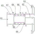
FIG. 3 is a schematic structural view of the mullion of the present invention;
fig. 4 is a schematic structural view of the inward opening window sash of the present invention;
wherein: the window comprises a window frame 1, pressing lines 2, a screen window outer frame 3, first glass 4, an inward-opening window sash 5 and a mullion 6;
the second glass 7, the screen sash 8, the screen sash port 81 and the duckbilled glue 9;
the clamping groove 51, the inner abdominal cavity 52, the outer abdominal cavity 53, the supporting section 54, the groove 55, the first heat insulation strip 56, the first dovetail-shaped clamping groove 57, the second dovetail-shaped clamping groove 58, the second heat insulation strip 59, the supporting strip and the standard c groove 511;
the inner frame 61, the outer frame 62, the process groove 63, the mounting groove 64, the heat insulation strip 65, the clamping strip 66, the clamping hook 67, the sealing rubber strip mounting groove 68 and the dovetail-shaped clamping groove 69.
Detailed Description
The technical solution of the present invention is further explained by the following embodiments with reference to the accompanying drawings.
In the description of the present invention, it is to be understood that the terms "center", "longitudinal", "lateral", "length", "width", "thickness", "upper", "lower", "left", "right", "vertical", "horizontal", "top", "bottom", "inner", "outer", "axial", "radial", "circumferential", and the like, indicate orientations or positional relationships based on those shown in the drawings, and are used merely for convenience of description and for simplicity of description, and do not indicate or imply that the device or element so referred to must have a particular orientation, be constructed and operated in a particular orientation, and thus should not be construed as limiting the present invention. Wherein, fig. 2 is a cross-sectional view of a-a in fig. 1, which is obtained by rotating 90 ° clockwise, and it should be noted that the components in circle B and circle B 'in fig. 1 are symmetrical structures, so the orientation description of the structure in B is opposite to that in B', i.e. the left side of the structure B is the right side of the structure B ', and the right side of the structure B is the left side of the structure B'.
As shown in fig. 2, the double inwardly opened window with the invisible drainage channel comprises a window frame 1, a mullion 6, an inwardly opened window sash 5 and a window screen outer frame 3, the window frame 1 is connected with one end of a first glass 4 through a pressing line 2, the other end of the first glass 4 is connected with a middle window 6 through the pressing line 2, the inner side surface of the mullion 6 is lapped with the extending part of the inner side surface of the inward-opening window sash 5 through a heat insulation rubber strip a, the extension part of the outer side surface of the mullion 6 is lapped with the outer screen frame 3 through the heat insulation rubber strip a, one side of the inward-opening window sash 5, which is far away from the first glass 4, is connected with the second glass 7 through the pressing line 2, the other end of the second glass 7 is connected with the inward-opening window sash through a pressing line 2, the extension part of the inner side surface of the inward-opening window sash 5 is lapped with the window frame 1 through a heat insulation adhesive tape a, the screen window outer frame 3 is lapped with the extending part of the outer side surface of the window frame 1 through a heat insulation rubber strip a;
the mullion 6 with the lateral surface of window frame 1 all is equipped with water drainage tank b, water drainage tank b is the U type, the left side of water drainage tank b's notch is inwards turned over, the slope of the right side place face of notch sets up.
Install water drainage tank b on the lateral surface of stile 6 and window frame 1 respectively, one side notch of this U type water drainage tank b turns over to the enstrophe, and is preferred, and inclination is good at 91-100, and the slope sets up the entering amount of reduction rainwater that can be fine, plays rain-proof water's function, another notch place side with water drainage tank b's bottom is the slope setting, can be with the effectual row of the water in water drainage tank b to outdoor, has avoided the condition of inslot ponding simultaneously, and the too big influence of angle of design is pleasing to the eye, and the angle undersize, and the drainage effect weakens. The utility model discloses the effectual problem of interior double open window can't get rid of ponding outside the window and the easy ponding of water drainage tank of having solved, simple structure and pleasing to the eye.
As shown in fig. 3, use B muntin as an example, in muntin 6 is including inside casing 61 and frame 62, inside casing 61 with frame 62 is positive relative setting, just inside casing 61 with the opposite face of frame 62 is equipped with relative dovetail draw-in groove 69 respectively, heat insulating strip 65 has been inserted between dovetail draw-in groove 69, heat insulating strip 65 extends card strip 66 left, inside casing 61 is close to dovetail draw-in groove 69 extends left and is equipped with pothook 67, pothook 67 with card strip 66 forms joint strip mounting groove 68, the extension section at the both ends of the lateral surface of frame 62 is equipped with mounting groove 64 respectively, the notch of mounting groove 64 sets up inwards.
Mullion 6 overall structure plays the effect of connecting first glass 4 and interior division of casement 5, has also played the effect of bearing first glass 4, and wherein the thermal-insulated thermal transmission of insulating strip 65 ability fine avoids outside cold empty to pass through frame 62 and transmits to inside casing 61 to transmit indoor, simultaneously, two extension sections also can play the effect of keeping off the arm, prevent that outdoor rainwater from getting into the interior division of casement window inside.
The notch of dovetail draw-in groove 69 is little, and the tank bottom is big, and the heat insulating strip 65 card that can be fine is to the groove in, prevents that heat insulating strip 65 from ageing to drop, and card strip 66 sets up and is used for lapping with duckbilled glue 9 and form airtight space in heat insulating strip 65 left end, and on the other hand forms joint strip mounting groove 68 with the combination of pothook 67. Two ends of the outer side surface of the outer frame 62 are respectively provided with an installation groove 64, and the two installation grooves 64 are respectively used for connecting the first glass 4 and the screen window outer frame 3.
To be further described, the left end surfaces of the outer frame 62 and the inner frame 61 are provided with a process groove 63.
The left end surfaces of the outer frame 62 and the inner frame 61 are both provided with process grooves 63, and the process grooves 63 are used for reducing material consumption, reducing cost and simultaneously ensuring that the appearance is not beautiful.
As shown in fig. 4, for example, the B' middle-inner-opening window sash, the inner-opening window sash 5 includes an inner abdominal cavity 52 and an outer abdominal cavity 53, the inner abdominal cavity 52 and the outer abdominal cavity 53 are oppositely disposed, corresponding first dovetail-shaped clamping grooves 57 and second dovetail-shaped clamping grooves 58 are respectively formed in opposite surfaces of the inner abdominal cavity 52 and the outer abdominal cavity 53, a first heat insulation strip 56 is inserted between the first opposite dovetail-shaped clamping grooves 57, a second heat insulation strip 59 is inserted between the second opposite dovetail-shaped clamping grooves 58, and a support strip 510 is extended from a surface of the first heat insulation strip 56 facing the mullion 6.
Interior casement 5 plays the effect of connecting stile 6 and second glass 7, and wherein the effect of first heat insulating strip 56 and second heat insulating strip 57 is the same with heat insulating strip 65 effect in the stile 6, all plays thermal-insulated effect, support bar 510 on the first heat insulating strip 56 is used for linking to each other with duckbilled glue 9, plays sealed effect, and wherein the effect of first dovetail draw-in groove 57 and second dovetail draw-in groove 58 is in order to avoid it to drop the notch in the better card to the notch of first heat insulating strip 56 and second heat insulating strip 57.
Further, a hook is vertically extended from the end surface of the internal abdominal cavity 52 far from the mullion 6, the inner side surface of the internal abdominal cavity 52 extends along the left end and the right end, a slot 51 is arranged on the extended portion of the right end, the extended portion of the left end and the hook form a standard c-shaped slot 511, the outer side surface of the external abdominal cavity 53 extends towards the left end, the left extended end sequentially comprises a supporting section 54 and a groove 55, and the supporting section 54 connects the groove 55 with the outer side surface of the external abdominal cavity 53.
The standard c groove 511 is used for limiting the position of the inward opening window sash 5, the pressing line 2 is conveniently fixed on the inward opening window sash 5 through the standard c groove 511, the clamping groove 51 is used for being connected with the window frame 1, the supporting section 54 is used for extending the position of the groove 55, the notch of the groove 55 and the upper end of the pressing line 2 are ensured to be located on the same horizontal plane, the weight of the second glass 7 is supported, and part of the weight is dispersed to the inward opening window sash 5.
In a further illustration, the duck bill glue comprises a duck bill glue 9, and the duck bill glue 9 is sleeved on the supporting strip 510 and is overlapped with the clamping strip 66.
The duckbilled glue 9 is sleeved on the support bar 510, and is in lap joint with the clamping strip 66, so that the cold air transmitted from the outer frame 3 of the screen window is well isolated outside the glass, and the cold air is prevented from entering the room.
In a further description, the duckbill glue 9, the supporting bars 510, the locking bars 66, the first insulating bars 56, the mullion 6 and the inward opening window sash 5 together form a closed space.
Duckbilled glue 9 encloses into an airtight space with support bar 510, card strip 66, first thermal-insulated adhesive tape 56, mullion 6 and interior division of casement 5 jointly, after closing the window, can play and prevent that the rainwater from getting into indoor effect, simultaneously, the air in the airtight space has also fine played thermal-insulated and syllable-dividing effect.
As shown in fig. 2, the screen window further comprises a magnetic strip 10, and the magnetic strip 10 is arranged between the opposite surfaces of the screen window sash 8 and the screen window outer frame 3.
The magnetic strip 10 is used for connecting the outer frame of the screen window and the screen sash, and is convenient for a user to detach, so that a large amount of manpower is saved.
As shown in fig. 2, the screen window sash further comprises a screen window sash port 81, the screen window sash port 81 is arranged on the inner frame surface of the screen window sash 8, and the screen window sash port 81 is serrated.
The screen window 81 is serrated, which is helpful for increasing friction force with the screen, and further fixes the screen in the screen window 8 to prevent the screen from falling off.
As shown in fig. 2, the two ends of the screen 8 in the vertical direction respectively abut against the bottoms of the screen fans 8.
Two ends of the gauze 8 in the vertical direction respectively abut against the bottom of the screen sash 8, so that on one hand, the distance between the gauze and the magnetic strip 10 can be reduced, the adsorption capacity of the gauze can be increased, on the other hand, the contact area between the gauze and the screen sash port 81 can be increased as much as possible, the friction force can be increased, and the gauze can be prevented from falling off.
The technical principle of the present invention is described above with reference to specific embodiments. The description is made for the purpose of illustrating the principles of the invention and should not be construed in any way as limiting the scope of the invention. Based on the explanations herein, those skilled in the art will be able to conceive of other embodiments of the present invention without any inventive effort, which would fall within the scope of the present invention.
Claims (10)
1. The utility model provides a two inwardly opened window with stealthy water drainage tank, includes window frame, mullion, interior casement and screen window frame, its characterized in that: the window frame is connected with one end of first glass through a pressing line, the other end of the first glass is connected to a middle support through the pressing line, the inner side surface of the middle support is in lap joint with the extending part of the inner side surface of the inward opening window sash through a heat insulation rubber strip a, the extending part of the outer side surface of the middle support is in lap joint with the window screen outer frame through the heat insulation rubber strip a, one side of the inward opening window sash, away from the first glass, is connected with second glass through the pressing line, the other end of the second glass is connected with the inward opening window sash through the pressing line, the extending part of the inner side surface of the inward opening window sash is in lap joint with the window frame through a heat insulation rubber strip a, and the;
the mullion with the lateral surface of window frame all is equipped with water drainage tank b, water drainage tank b is the U type, the left side of water drainage tank b's notch is inwards turned over and is rolled over, the slope of the right side place face of notch sets up.
2. The double inwardly opened window with the invisible drainage channel as claimed in claim 1, wherein: the muntin is including inside casing and frame, the inside casing with the frame is just setting up relatively, just the inside casing with the opposite face of frame is equipped with relative dovetail draw-in groove respectively, it has the heat insulating strip to insert between the dovetail draw-in groove, the heat insulating strip extends the card strip left, the inside casing is close to the dovetail draw-in groove extends left and is equipped with the pothook, the pothook with the card strip forms the joint strip mounting groove, the extension section at the both ends of the lateral surface of frame is equipped with the mounting groove respectively, the notch of mounting groove sets up inwards.
3. The double inwardly opened window with the invisible drainage channel as claimed in claim 2, wherein: the left end faces of the outer frame and the inner frame are both provided with process grooves.
4. The double inwardly opened window with the invisible drainage channel as claimed in claim 2, wherein: interior division of casement is including interior abdominal cavity and outer abdominal cavity, interior abdominal cavity with outer abdominal cavity sets up relatively, just interior abdominal cavity with corresponding first swallow-tail shape draw-in groove and second swallow-tail shape draw-in groove have all been seted up to outer abdominal cavity's opposite face, and is relative insert first heat insulating strip between first side swallow-tail shape draw-in groove, and is relative insert the heat insulating strip of second between second swallow-tail shape draw-in groove, first heat insulating strip orientation the face of well stile extends and is equipped with the support bar.
5. The double inwardly opened window with the invisible drainage channel as set forth in claim 4, wherein: the end face, far away from the mullion, of the inner abdominal cavity extends vertically to form a clamping hook, the inner side face of the inner abdominal cavity extends along the left end and the right end, the extending portion of the right end is provided with a clamping groove, the extending portion of the left end and the clamping hook form a standard c groove, the outer side face of the outer abdominal cavity extends towards the left end, the left extending end sequentially comprises a supporting section and a groove, and the supporting section connects the groove with the outer side face of the outer abdominal cavity.
6. The double inwardly opened window with the invisible drainage channel as claimed in claim 5, wherein: still include the duckbilled glue, the duckbilled gum cover is located the support bar, with card strip overlap joint.
7. The double inwardly opened window with the invisible drainage channel as set forth in claim 6, wherein: the duckbilled glue, the supporting strips, the clamping strips, the first heat insulation strips, the mullion and the inward-opening window sash jointly enclose a closed space.
8. The double inwardly opened window with the invisible drainage channel as claimed in claim 1, wherein: the screen window is characterized by further comprising a magnetic strip and a screen sash, wherein the magnetic strip is arranged between the screen sash and the opposite surface of the screen window outer frame.
9. The dual inwardly opened window with the invisible drainage channel as set forth in claim 8, wherein: the screen window is characterized by further comprising screen window sash ports, wherein the screen window sash ports are arranged on the inner frame surface of the screen window sash and are in a sawtooth shape.
10. The dual inwardly opened window with the invisible drainage channel as set forth in claim 8, wherein: the screen window is characterized by further comprising a screen, wherein two ends of the screen in the vertical direction are respectively abutted against the bottoms of the screen fans.
Priority Applications (1)
| Application Number | Priority Date | Filing Date | Title |
|---|---|---|---|
| CN201922438985.7U CN211666533U (en) | 2019-12-30 | 2019-12-30 | Double-inward opening window with invisible drainage channel |
Applications Claiming Priority (1)
| Application Number | Priority Date | Filing Date | Title |
|---|---|---|---|
| CN201922438985.7U CN211666533U (en) | 2019-12-30 | 2019-12-30 | Double-inward opening window with invisible drainage channel |
Publications (1)
| Publication Number | Publication Date |
|---|---|
| CN211666533U true CN211666533U (en) | 2020-10-13 |
Family
ID=72737443
Family Applications (1)
| Application Number | Title | Priority Date | Filing Date |
|---|---|---|---|
| CN201922438985.7U Active CN211666533U (en) | 2019-12-30 | 2019-12-30 | Double-inward opening window with invisible drainage channel |
Country Status (1)
| Country | Link |
|---|---|
| CN (1) | CN211666533U (en) |
Cited By (1)
| Publication number | Priority date | Publication date | Assignee | Title |
|---|---|---|---|---|
| CN114753756A (en) * | 2022-03-18 | 2022-07-15 | 斯卡特(北京)智能科技有限公司 | Bridge cut-off aluminum alloy inwardly opened window |
-
2019
- 2019-12-30 CN CN201922438985.7U patent/CN211666533U/en active Active
Cited By (2)
| Publication number | Priority date | Publication date | Assignee | Title |
|---|---|---|---|---|
| CN114753756A (en) * | 2022-03-18 | 2022-07-15 | 斯卡特(北京)智能科技有限公司 | Bridge cut-off aluminum alloy inwardly opened window |
| CN114753756B (en) * | 2022-03-18 | 2024-01-12 | 斯卡特(北京)智能科技有限公司 | Bridge-cutoff aluminum alloy inward opening window |
Similar Documents
| Publication | Publication Date | Title |
|---|---|---|
| CN211666533U (en) | Double-inward opening window with invisible drainage channel | |
| CN213980439U (en) | Double-bridge-cutoff heat-insulation window structure | |
| CN206571344U (en) | Hand-rail type swinging-out casement window with screen window | |
| CN212507911U (en) | Semi-hidden frame type inward casement strip window system | |
| CN209959057U (en) | Five sealed windows | |
| CN201137405Y (en) | Internal-opening aluminum alloy window with window screen | |
| CN207048569U (en) | A kind of pseudo-classic window of aluminium bag wood Chinese style | |
| CN210317017U (en) | Inward-opening single-sash window profile | |
| CN210828846U (en) | Independent low-energy-consumption casement inner-hung window | |
| CN219101084U (en) | Heat-insulating inner casement window with screen window | |
| CN216617277U (en) | Double-inward opening system sealing window | |
| CN217652633U (en) | Heat-insulation energy-saving sliding window | |
| CN215979008U (en) | Top-hung window | |
| CN211115459U (en) | Frame assembly of outward-opening door with external heat preservation function | |
| CN217206080U (en) | Sliding window with good sealing effect | |
| CN210738353U (en) | Aluminum alloy door and window with interior division of screen window structure | |
| CN214616084U (en) | Door and window installation device | |
| CN216617281U (en) | External-open system sealing window | |
| CN218029778U (en) | Heat-insulation casement window | |
| CN213175331U (en) | Energy-saving sliding door and window | |
| CN216741168U (en) | A section bar structure for swinging-out casement window | |
| CN220522420U (en) | Flat-open heat insulation window structure in unit type curtain wall with windowsill | |
| CN218716247U (en) | Waterproof aluminum alloy door and window | |
| CN215108519U (en) | Window heat insulation structure | |
| CN211115602U (en) | Outward-opening top-hung window structure |
Legal Events
| Date | Code | Title | Description |
|---|---|---|---|
| GR01 | Patent grant | ||
| GR01 | Patent grant |