CN217652633U - Heat-insulation energy-saving sliding window - Google Patents
Heat-insulation energy-saving sliding window Download PDFInfo
- Publication number
- CN217652633U CN217652633U CN202220170237.4U CN202220170237U CN217652633U CN 217652633 U CN217652633 U CN 217652633U CN 202220170237 U CN202220170237 U CN 202220170237U CN 217652633 U CN217652633 U CN 217652633U
- Authority
- CN
- China
- Prior art keywords
- hooked rabbet
- heat
- frame
- hooked
- cover
- Prior art date
- Legal status (The legal status is an assumption and is not a legal conclusion. Google has not performed a legal analysis and makes no representation as to the accuracy of the status listed.)
- Active
Links
Images


Abstract
The utility model discloses a heat-insulating and energy-saving sliding window, which comprises a window frame, an inner sash and an outer sash; the inner window sash comprises a first hooked rabbet and a first lower part; the outer window sash comprises a second hooked rabbet and a second lower part; a first hooked rabbet cover is arranged on the first hooked rabbet, and a second hooked rabbet cover is arranged on the second hooked rabbet; a first heat insulation piece is arranged between the first hooked rabbet and the first hooked rabbet cover, and a second heat insulation piece is arranged between the second hooked rabbet and the second hooked rabbet cover. The utility model is provided with a structure which is connected with and matched with the first heat insulation piece and the second heat insulation piece on the first hooked rabbet, the second hooked rabbet and the corresponding hooked rabbet covers, and the gap at the joint of the inner window sash and the outer window sash is sealed; meanwhile, the inner guide rail which slides downwards is arranged on the lug boss, so that the inner guide rail is higher than the outer guide rail, the first lower part and the second lower part are arranged in a vertically staggered manner, and the flow of cold and hot air is blocked; thereby improving the heat insulation and sealing performance of the joint of the inner sash and the outer sash and the joint of the lower slide and the sash and achieving the purpose of energy conservation.
Description
Technical Field
The utility model relates to a door and window technical field especially relates to a thermal-insulated energy-conserving austral window, sliding sash.
Background
The sliding window is a window widely accepted at present, and window sashes arranged in a window frame can respectively slide along corresponding guide rails; when one of the sashes needs to be opened, the sash is only required to be slid to the direction of the other sash.
However, due to the limitation of the structure of the heat-insulating sliding window in the prior art, a gap still exists between the window sash and the edge seal when the window sash is closed, the sealing effect is poor, the air tightness is poor, and the heat exchange between the indoor space and the outdoor space causes the poor heat-insulating and energy-saving effect.
Therefore, it is urgently needed to provide a heat-insulating and energy-saving sliding window which is reasonable in design and has good heat-insulating and energy-saving effects.
SUMMERY OF THE UTILITY MODEL
In order to solve the above problem, the utility model discloses the technical scheme who adopts as follows:
a heat-insulating energy-saving sliding window comprises a window frame, an inner window sash and an outer window sash, and is characterized in that the inner window sash comprises a first hooked rabbet and a first lower part; the outer window sash comprises a second hooked rabbet and a second lower part;
the first hooked rabbet cover is arranged on the first hooked rabbet, and the second hooked rabbet cover is arranged on the second hooked rabbet; a first heat insulation piece is arranged between the first hooked rabbet and the first hooked rabbet cover, and a second heat insulation piece is arranged between the second hooked rabbet and the second hooked rabbet cover.
Preferably, the first hooked rabbet comprises a first hooked rabbet inner frame and a first hooked rabbet outer frame which are connected in a clamping manner through a penetrating strip; the second hooked rabbet comprises a second hooked rabbet inner frame and a second hooked rabbet outer frame which are connected in a clamping manner through a penetrating strip;
the first hooked rabbet inner frame comprises a first hooked rabbet inner frame body, a first clamping groove and a first connecting edge, wherein the first clamping groove and the first connecting edge are arranged on the left side and the right side of the first hooked rabbet inner frame body;
the first hooked rabbet outer frame comprises a first hooked rabbet outer frame body, a first limiting edge and a second connecting edge, wherein the first limiting edge and the second connecting edge are arranged on the left side and the right side of the first hooked rabbet outer frame body;
the first hooked rabbet cover comprises an L-shaped first hooked rabbet cover body, one end of the first hooked rabbet cover body supports the first limiting edge, and the other end of the first hooked rabbet cover body is provided with a first hooked rabbet cover clamping hook clamped with the first clamping groove; the first heat insulation piece is positioned at the joint of the first limiting edge and the first hooked rabbet cover body;
the second hooked rabbet inner frame comprises a second hooked rabbet inner frame body, and fourth connecting edges and second limiting edges which are arranged on the left side and the right side of the second hooked rabbet inner frame body;
the second hook rabbet outer frame comprises a second hook rabbet outer frame body, third connecting edges and second clamping grooves, wherein the third connecting edges and the second clamping grooves are arranged on the left side and the right side of the second hook rabbet outer frame body;
the second hooked rabbet cover comprises an L-shaped second hooked rabbet cover body, one end of the second hooked rabbet cover body supports the second limiting edge, and the other end of the second hooked rabbet cover body is provided with a second hooked rabbet cover clamping hook clamped with the second clamping groove; the second heat insulation piece is positioned at the joint of the second limiting edge and the second hooked rabbet cover body;
first glass is arranged between the first connecting edge and the second connecting edge and between the third connecting edge and the fourth connecting edge respectively.
Preferably, the first heat insulation piece and the second heat insulation piece are the same structural body and respectively comprise an L-shaped heat insulation piece body, and the heat insulation piece body is positioned at the joint of the first limiting edge and the first hooked rabbet cover body or at the joint of the second limiting edge and the second hooked rabbet cover body;
one end of the heat insulation piece body extends towards the direction of the first hooked rabbet cover hook or the second hooked rabbet cover hook, and the other end of the heat insulation piece body is provided with a connecting part in an L-shaped structure body; one end of the connecting part is connected with the heat insulation part body, and the width of the other end is gradually reduced towards the direction far away from the heat insulation part body.
Preferably, a third clamping groove is formed in one side, facing the fourth connecting edge, of the first hooked rabbet cover body; a fourth clamping groove is formed in one side, facing the second connecting edge, of the second hooked rabbet cover body; and silicification wool tops are arranged on the third clamping groove and the fourth clamping groove.
Preferably, the window frame comprises a lower slide; the lower slide comprises an inner lower slide frame and an outer lower slide frame which are connected through a threading snap;
the inner lower sliding frame comprises an inner lower sliding frame body and a boss protruding upwards along the inner lower sliding frame body; the boss is provided with an inner guide rail extending upwards along the boss; the outer downward sliding frame comprises an outer downward sliding frame body and an outer guide rail extending upwards along the outer downward sliding frame body; the inner guide rail is higher than the outer guide rail;
the first lower part is connected with the inner guide rail in a sliding mode, and the second lower part is connected with the outer guide rail in a sliding mode.
Preferably, a flange extending upwards along the inner sliding frame body is arranged on the inner side of the inner sliding frame body; the flange is positioned on one side of the first lower part.
Preferably, a fifth clamping groove is formed in one side, facing the first lower side, of the flange; and silicification wool tops are arranged on the fifth clamping grooves.
Preferably, the window frame, the inner sash and the outer sash are all extruded aluminum profiles.
Compared with the prior art, the beneficial effects of the utility model reside in that:
the utility model has the advantages that the first heat insulation part and the second heat insulation part which are composed of the L-shaped heat insulation part body and the L-shaped connecting part are respectively arranged in the middle of the connecting part of the first hooked rabbet and the second hooked rabbet, and the structures which are connected with the first heat insulation part and the second heat insulation part and are matched with the first hooked rabbet, the second hooked rabbet and the corresponding hooked rabbet covers are arranged on the first hooked rabbet, the second hooked rabbet and the corresponding hooked rabbet covers, so that the gap between the connecting part of the inner sash and the outer sash is sealed; meanwhile, the inner guide rail of the lower slide is arranged on the lug boss of the inner lower slide frame body, so that the inner guide rail is higher than the outer guide rail, the first lower part and the second lower part are arranged in a vertically staggered manner, and the flow of cold and hot air is blocked; therefore, the heat insulation and sealing performance of the joint of the inner sash and the outer sash and the joint of the downslide and the sash of the window frame are improved, the heat insulation effect is greatly improved, and the purpose of energy conservation is achieved.
Drawings
Fig. 1 is a front view of the present invention;
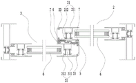
FIG. 2 isbase:Sub>A schematic view of the cross-sectional structure A-A in FIG. 1;
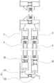
FIG. 3 is a schematic view of the cross-sectional structure B-B in FIG. 1;
fig. 4 is a schematic cross-sectional view of the first hooked rabbet and the second hooked rabbet of the present invention;
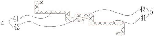
FIG. 5 is a schematic cross-sectional view of a first insulation element and a second insulation element of the present invention;
FIG. 6 is a schematic cross-sectional view of the middle slide of the present invention;
wherein: the window frame comprises a window frame 1, an inner window sash 2, an outer window sash 3, a first heat insulation part 4, a second heat insulation part 5, first glass 6, a silicified wool strip 7, a lower slide 11, a first hooked rabbet 21, a first lower part 22, a first hooked rabbet cover 23, a second hooked rabbet 31, a second lower part 32, a second hooked rabbet cover 33, a heat insulation part body 41, a connecting part 42, an inner lower slide frame 111, an outer lower slide frame 112, a first hooked rabbet inner frame 211, a first hooked rabbet outer frame 212, a first hooked rabbet cover body 231, a first hooked rabbet cover hook 232, a third slot 233, a second hooked rabbet inner frame 311, a second hooked rabbet outer frame 312, a second hooked rabbet cover body 331, a second hooked rabbet cover hook 332, a fourth slot 333, an inner hooked rabbet frame body 1111, a boss 1112, an inner guide rail 1113, a flange 1114, a fifth slot 1115, an outer lower slide frame body 1121, an outer guide rail 1122, a first rabbet body 3113113111, a first lower slide frame body 2113, a first connecting edge rabbet body 2123123, a second outer frame body, a second hooked rabbet 2123121, a second outer frame body, a second hooked rabbet 3112, a second outer frame 2123123, a second outer frame body, a second limiting frame 2123 and a second limiting frame 2122.
Detailed Description
In order to facilitate understanding of the present invention, the present invention will be described more fully hereinafter with reference to the accompanying drawings. Preferred embodiments of the present invention are shown in the drawings. The invention may, however, be embodied in many different forms and should not be construed as limited to the embodiments set forth herein. Rather, these embodiments are provided so that this disclosure will be thorough and complete.
It will be understood that when an element is referred to as being "secured to" another element, it can be directly on the other element or intervening elements may also be present. When an element is referred to as being "connected" to another element, it can be directly connected to the other element or intervening elements may also be present. The terms "vertical," "horizontal," "front," "back," "left," "right," "up," "down," and the like as used herein are for illustrative purposes only.
Unless defined otherwise, all technical and scientific terms used herein have the same meaning as commonly understood by one of ordinary skill in the art to which this invention belongs. The terminology used in the description of the invention herein is for the purpose of describing particular embodiments only and is not intended to be limiting of the invention. As used herein, the term "and/or" includes any and all combinations of one or more of the associated listed items.
The invention will be further described with reference to the following drawings and detailed description:
as shown in fig. 1-6, a heat-insulating energy-saving sliding window comprises a window frame 1, an inner sash 2 and an outer sash 3, and is characterized in that the inner sash 2 comprises a first hooked rabbet 21 and a first lower portion 22; the outer window sash 3 comprises a second hooked rabbet 31 and a second lower part 32;
a first hooked rabbet cover 23 is arranged on the first hooked rabbet 21, and a second hooked rabbet cover 33 is arranged on the second hooked rabbet 31; a first heat insulation piece 4 is arranged between the first hooked rabbet 21 and the first hooked rabbet cover 23, and a second heat insulation piece 5 is arranged between the second hooked rabbet 31 and the second hooked rabbet cover 33.
In this embodiment, when the inner window sash 2 and the outer window sash 3 are in a closed state, the first hooked rabbet 21 and the second hooked rabbet 31 are correspondingly arranged, and the first heat insulating piece 4 and the second heat insulating piece 5 seal the joint of the first hooked rabbet 21 and the second hooked rabbet 31, so that a gap between the joint of the inner window sash 2 and the outer window sash 3 is sealed, heat exchange between the inner chamber and the outer chamber is reduced, and heat insulation and sealing performance of the joint of the inner window sash 2 and the outer window sash 3 are improved.
Further, as shown in fig. 2 and 4, the first hooked rabbet 21 includes a first hooked rabbet inner frame 211 and a first hooked rabbet outer frame 212 which are connected by a through strip in a snap-fit manner; the second hooked rabbet 31 comprises a second hooked rabbet inner frame 311 and a second hooked rabbet outer frame 312 which are connected in a clamping manner through a penetrating strip;
the first hooked rabbet inner frame 211 comprises a first hooked rabbet inner frame body 2111, a first clamping groove 2112 and a first connecting edge 2113, wherein the first clamping groove 2112 and the first connecting edge are arranged on the left side and the right side of the first hooked rabbet inner frame body 2111;
the first hooked rabbet outer frame 212 comprises a first hooked rabbet outer frame body 2121, and a first limiting edge 2122 and a second connecting edge 2123 which are arranged on the left side and the right side of the first hooked rabbet outer frame body 2121;
the first hooked rabbet cover 23 comprises an L-shaped first hooked rabbet cover body 231, one end of the first hooked rabbet cover body 231 supports the first limiting edge 2122, and the other end of the first hooked rabbet cover body 231 is provided with a first hooked rabbet cover clamping hook 232 clamped with the first clamping groove 2112; the first heat insulation piece 4 is positioned at the joint of the first limiting edge 2122 and the first hooked rabbet cover body 231;
the second hooked rabbet inner frame 311 includes a second hooked rabbet inner frame body 3111, and a fourth connecting edge 3112 and a second limiting edge 3113 provided on the left and right sides of the second hooked rabbet inner frame body 3111;
the second hooked rabbet outer frame 312 comprises a second hooked rabbet outer frame body 3121, and a third connecting edge 3122 and a second clamping groove 3123 which are arranged on the left side and the right side of the second hooked rabbet outer frame body 3121;
the second hooked rabbet cover 33 comprises an L-shaped second hooked rabbet cover body 331, one end of the second hooked rabbet cover body 331 supports the second limiting edge 3113, and the other end is provided with a second hooked rabbet cover hook 332 clamped with the second clamping groove 3123; the second heat insulation piece 5 is positioned at the joint of the second limiting edge 3113 and the second hooked rabbet cover body 331;
a first glass 6 is respectively arranged between the first connecting edge 2113 and the second connecting edge 2123 and between the third connecting edge 3122 and the fourth connecting edge 3112.
In this embodiment, the first hooked rabbet cover 23 and the second hooked rabbet cover 33 are arranged to stably and firmly arrange the first heat insulating element 4 and the second heat insulating element 5 on the first hooked rabbet 21 and the second hooked rabbet 31, so as to prevent the right window sash and the left window sash from falling or loosening in the sliding process, and further improve the sealing reliability of the sliding window.
In this embodiment, the first glass 6 is bonded using a silicone structural sealant; the first connecting edge 2113 and the second connecting edge 2123 are bonded with the first glass 6 under the action of silicone structural sealant; the third connecting edge 3122 and the fourth connecting edge 3112 are bonded with the first glass 6 under the action of silicone structural sealant; the first glass 6 is glass with a double-layer hollow structure, and heat insulation sealant is arranged around the hollow glass.
Further, as shown in fig. 2 and 5, the first heat insulating element 4 and the second heat insulating element 5 are the same structure, and both include an "L" -shaped heat insulating element body 41, where the heat insulating element body 41 is located at a connection between the first limiting edge 2122 and the first hooked rabbet cover body 231 or at a connection between the second limiting edge 3113 and the second hooked rabbet cover body 331;
one end of the heat insulation element body 41 extends towards the direction of the first hooked rabbet cover hook 232 or the second hooked rabbet cover hook 332, and the other end is provided with a connecting part 42 in an L-shaped structure body; one end of the connecting portion 42 is connected to the heat insulator body 41, and the width of the other end is gradually reduced in a direction away from the heat insulator body 41.
In this embodiment, the heat insulating member bodies 41 of the first heat insulating member 4 and the second heat insulating member 5 are respectively disposed at the connection position of the first limiting edge 2122 and the first hooked rabbet cover body 231 and the connection position of the second limiting edge 3113 and the second hooked rabbet cover body 331, so that not only can the connection tightness between the first hooked rabbet cover 23 and the first hooked rabbet outer frame 212 and between the second hooked rabbet cover 33 and the second hooked rabbet inner frame 311 be improved, but also the connection strength between the first heat insulating member 4 and the second heat insulating member 5 and the first hooked rabbet 21 and the second hooked rabbet 31 can be improved.
In this embodiment, the connecting portion 42 of the first heat insulating material 4 and the connecting portion 42 of the second heat insulating material 5 are connected at one end thereof, and the width of the connecting portion is gradually reduced in a direction away from the heat insulating material body 41, so that the strength of the connecting portion 42 is ensured, and excellent sealing performance can be achieved.
Further, as shown in fig. 2 and 4, a third slot 233 is disposed on one side of the first hooked rabbet cover body 231 facing the fourth connecting edge 3112; a fourth clamping groove 333 is formed in one side, facing the second connecting edge 2123, of the second hooked rabbet cover 331; the third slot 233 and the fourth slot 333 are provided with siliconized wool tops 7.
In this embodiment, the first-stage partition is formed by providing the siliconized wool tops 7 on the right side of the second hooked rabbet 31 and the left side of the first hooked rabbet 21; the first heat insulation piece 4 and the second heat insulation piece 5 which are connected with each other are respectively arranged in the middle of the joint of the second hooked rabbet 31 and the first hooked rabbet 21 to form a second-stage partition, so that the flow of cold air and hot air can be effectively blocked, and good heat insulation, energy saving and sound insulation effects are achieved; and moreover, impurities such as dust and the like are reduced from being adhered to the first heat insulating part 4 and the second heat insulating part 5 by arranging the silicification wool tops 7, and the energy-saving heat insulating effect is ensured.
Further, as shown in fig. 3 and 6, the window frame 1 comprises a lower slide 11; the lower slide 11 comprises an inner lower slide frame 111 and an outer lower slide frame 112 which are connected through a threading snap;
the inner lower sliding frame 111 includes an inner lower sliding frame body 1111 and a boss 1112 protruding upward along the inner lower sliding frame body 1111; the boss 1112 is provided with an inner guide rail 1113 extending upwards along the boss 1112; the outer down-slide frame 112 includes an outer down-slide frame body 1121 and an outer guide rail 1122 extending upward along the outer down-slide frame body 1121; the inner guide rail 1113 is higher than the outer guide rail 1122;
the first lower portion 22 is slidably coupled to the inner track 1113 and the second lower portion 32 is slidably coupled to the outer track 1122.
In this embodiment, the inner guide rail 1113 is arranged on the boss 1112 of the inner lower sliding frame body 1111, so that the inner guide rail 1113 is higher than the outer guide rail 1122, and thus the first lower part 22 and the second lower part 32 are arranged in a vertically staggered manner.
Further, as shown in fig. 3 and 6, a rib 1114 extending upwards along the inner lower sliding frame body 1111 is arranged on the inner side of the inner lower sliding frame body 1111; the rib 1114 is located on one side of the first lower side 22.
Further, as shown in fig. 6, a fifth card slot 1115 is disposed on a side of the flange 1114 facing the first lower side 22; and the fifth clamping groove 1115 is provided with silicified wool tops 7.
In this embodiment, a first level of separation is formed by providing siliconized wool tops 7 between the ribs 1114 and the first lower side 22; the inner guide rail 1113 is arranged on the boss 1112 of the inner sliding frame body 1111, so that the inner guide rail 1113 is higher than the outer guide rail 1122, the first lower part 22 and the second lower part 32 are arranged in a vertically staggered manner, a second-stage partition is formed, and the heat insulation and sealing performance of the joint of the sliding lower 11 and the inner window sash 2 and the outer window sash 3 is improved.
Furthermore, the window frame 1, the inner sash 2 and the outer sash 3 are all extruded aluminum profiles.
Various other modifications and changes may be made by those skilled in the art based on the above-described technical solutions and concepts, and all such modifications and changes are intended to fall within the scope of the present invention.
Claims (8)
1. A heat-insulating energy-saving sliding window comprises a window frame, an inner window sash and an outer window sash, and is characterized in that the inner window sash comprises a first hooked rabbet and a first lower part; the outer window sash comprises a second hooked rabbet and a second lower part;
the first hooked rabbet cover is arranged on the first hooked rabbet, and the second hooked rabbet cover is arranged on the second hooked rabbet; a first heat insulation piece is arranged between the first hooked rabbet and the first hooked rabbet cover, and a second heat insulation piece is arranged between the second hooked rabbet and the second hooked rabbet cover.
2. The heat-insulating energy-saving sliding window according to claim 1, wherein the first hooked rabbet comprises a first hooked rabbet inner frame and a first hooked rabbet outer frame which are connected through a penetrating strip in a clamping manner; the second hooked rabbet comprises a second hooked rabbet inner frame and a second hooked rabbet outer frame which are connected in a clamping manner through a penetrating strip;
the first hooked rabbet inner frame comprises a first hooked rabbet inner frame body, a first clamping groove and a first connecting edge, wherein the first clamping groove and the first connecting edge are arranged on the left side and the right side of the first hooked rabbet inner frame body;
the first hooked rabbet outer frame comprises a first hooked rabbet outer frame body, a first limiting edge and a second connecting edge, wherein the first limiting edge and the second connecting edge are arranged on the left side and the right side of the first hooked rabbet outer frame body;
the first hooked rabbet cover comprises an L-shaped first hooked rabbet cover body, one end of the first hooked rabbet cover body supports the first limiting edge, and the other end of the first hooked rabbet cover body is provided with a first hooked rabbet cover clamping hook clamped with the first clamping groove; the first heat insulation piece is positioned at the joint of the first limiting edge and the first hooked rabbet cover body;
the second hooked rabbet inner frame comprises a second hooked rabbet inner frame body, and fourth connecting edges and second limiting edges which are arranged on the left side and the right side of the second hooked rabbet inner frame body;
the second hooked rabbet outer frame comprises a second hooked rabbet outer frame body, third connecting edges and second clamping grooves, wherein the third connecting edges and the second clamping grooves are arranged on the left side and the right side of the second hooked rabbet outer frame body;
the second hooked rabbet cover comprises an L-shaped second hooked rabbet cover body, one end of the second hooked rabbet cover body supports the second limiting edge, and the other end of the second hooked rabbet cover body is provided with a second hooked rabbet cover clamping hook clamped with the second clamping groove; the second heat insulation piece is positioned at the joint of the second limiting edge and the second hooked rabbet cover body;
first glass is respectively arranged between the first connecting edge and the second connecting edge and between the third connecting edge and the fourth connecting edge.
3. The heat-insulating energy-saving sliding window according to claim 2, wherein the first heat-insulating piece and the second heat-insulating piece are the same structural body and both comprise an L-shaped heat-insulating piece body, and the heat-insulating piece body is positioned at the joint of the first limiting edge and the first hooked rabbet cover body or at the joint of the second limiting edge and the second hooked rabbet cover body;
one end of the heat insulation piece body extends towards the direction of the first hooked rabbet cover hook or the second hooked rabbet cover hook, and the other end of the heat insulation piece body is provided with a connecting part in an L-shaped structure body; one end of the connecting part is connected with the heat insulation part body, and the width of the other end is gradually reduced towards the direction far away from the heat insulation part body.
4. The heat-insulating energy-saving sliding window as claimed in claim 3, wherein a third clamping groove is formed in one side, facing the fourth connecting edge, of the first hooked rabbet cover body; a fourth clamping groove is formed in one side, facing the second connecting edge, of the second hooked rabbet cover body; and silicification wool tops are arranged on the third clamping groove and the fourth clamping groove.
5. An insulating and energy-saving sliding window according to claim 1, characterized in that the window frame comprises a lower slide; the lower slide comprises an inner lower slide frame and an outer lower slide frame which are connected through a threading snap;
the inner lower sliding frame comprises an inner lower sliding frame body and a boss protruding upwards along the inner lower sliding frame body; the boss is provided with an inner guide rail extending upwards along the boss; the outer downward sliding frame comprises an outer downward sliding frame body and an outer guide rail extending upwards along the outer downward sliding frame body; the inner guide rail is higher than the outer guide rail;
the first lower part is connected with the inner guide rail in a sliding mode, and the second lower part is connected with the outer guide rail in a sliding mode.
6. A heat-insulating energy-saving sliding window according to claim 5, characterized in that a flange extending upwards along the inner lower sliding frame body is arranged on the inner side of the inner lower sliding frame body; the flange is positioned on one side of the first lower part.
7. The heat-insulating energy-saving sliding window according to claim 6, wherein a fifth clamping groove is formed in one side, facing the first lower side, of the flange; and silicification wool tops are arranged on the fifth clamping grooves.
8. An insulating and energy-saving sliding window according to claim 1, characterized in that the window frame, the inner sash and the outer sash are extruded aluminum profiles.
Priority Applications (1)
| Application Number | Priority Date | Filing Date | Title |
|---|---|---|---|
| CN202220170237.4U CN217652633U (en) | 2022-01-21 | 2022-01-21 | Heat-insulation energy-saving sliding window |
Applications Claiming Priority (1)
| Application Number | Priority Date | Filing Date | Title |
|---|---|---|---|
| CN202220170237.4U CN217652633U (en) | 2022-01-21 | 2022-01-21 | Heat-insulation energy-saving sliding window |
Publications (1)
| Publication Number | Publication Date |
|---|---|
| CN217652633U true CN217652633U (en) | 2022-10-25 |
Family
ID=83661028
Family Applications (1)
| Application Number | Title | Priority Date | Filing Date |
|---|---|---|---|
| CN202220170237.4U Active CN217652633U (en) | 2022-01-21 | 2022-01-21 | Heat-insulation energy-saving sliding window |
Country Status (1)
| Country | Link |
|---|---|
| CN (1) | CN217652633U (en) |
-
2022
- 2022-01-21 CN CN202220170237.4U patent/CN217652633U/en active Active
Similar Documents
| Publication | Publication Date | Title |
|---|---|---|
| CN104989229A (en) | Door and window structure of top-hung window | |
| CN217652633U (en) | Heat-insulation energy-saving sliding window | |
| CN202509965U (en) | 75-series heat-insulation energy-saving aluminum alloy sliding window | |
| CN207377410U (en) | A kind of aluminium alloy out-open window | |
| CN207377389U (en) | A kind of aluminium alloy out-open window | |
| CN207377391U (en) | A kind of aluminium alloy out-open window | |
| CN207377384U (en) | A kind of aluminium alloy out-open window | |
| CN207377390U (en) | A kind of aluminium alloy out-open window | |
| CN207377383U (en) | A kind of aluminium alloy out-open window | |
| CN207377411U (en) | A kind of aluminium alloy out-open window | |
| CN207377382U (en) | A kind of aluminium alloy out-open window | |
| CN207377377U (en) | A kind of aluminium alloy out-open window | |
| CN207377396U (en) | A kind of aluminium alloy out-open window | |
| CN207377393U (en) | A kind of aluminium alloy out-open window | |
| CN207377378U (en) | A kind of aluminium alloy out-open window | |
| CN112523640A (en) | Novel sliding window | |
| CN207377398U (en) | A kind of aluminium alloy out-open window | |
| CN207377392U (en) | A kind of aluminium alloy out-open window | |
| CN207377376U (en) | A kind of aluminium alloy inwardly opened window | |
| CN218912661U (en) | Sealing structure of aluminum alloy side-shifting sliding window | |
| CN213175331U (en) | Energy-saving sliding door and window | |
| CN215369411U (en) | Common casement window | |
| CN216157538U (en) | Novel outward opening window structure | |
| CN216974581U (en) | Sliding window seal structure of environment-friendly | |
| CN218029778U (en) | Heat-insulation casement window |
Legal Events
| Date | Code | Title | Description |
|---|---|---|---|
| GR01 | Patent grant | ||
| GR01 | Patent grant |