CN211567219U - Be applied to laminating machine in relief (sculpture) transfer connects paper production - Google Patents
Be applied to laminating machine in relief (sculpture) transfer connects paper production Download PDFInfo
- Publication number
- CN211567219U CN211567219U CN201922300861.2U CN201922300861U CN211567219U CN 211567219 U CN211567219 U CN 211567219U CN 201922300861 U CN201922300861 U CN 201922300861U CN 211567219 U CN211567219 U CN 211567219U
- Authority
- CN
- China
- Prior art keywords
- roller
- pressure roller
- frame
- movable arm
- transfer paper
- Prior art date
- Legal status (The legal status is an assumption and is not a legal conclusion. Google has not performed a legal analysis and makes no representation as to the accuracy of the status listed.)
- Active
Links
Images


Landscapes
- Lining Or Joining Of Plastics Or The Like (AREA)
Abstract
The utility model relates to a film laminating machine applied to the production of embossment transfer paper, which comprises a frame base and a frame side plate, wherein a discharge roller, a film laminating assembly and a receiving roller are arranged on the frame side plate, the film laminating assembly is arranged between the discharge roller and the film roller, the film laminating assembly comprises a heating roller, a first pressure roller and a second pressure roller, the first pressure roller and the heating roller are horizontally arranged, the second pressure roller is arranged below the first pressure roller, a support frame is arranged on the frame side plate, a first cylinder is arranged on the support frame, the first cylinder is hinged with a movable arm through a connecting block, the other end of the movable arm is hinged with the first pressure roller, the middle of the movable arm is hinged with a pin shaft fixed on the frame, an elastic component is arranged on the frame base, the elastic component is connected with the second pressure roller, the utility model can provide enough pressure when laminating the embossment transfer paper, so that the film can be smoothly compounded on the embossed transfer paper.
Description
Technical Field
The utility model relates to a laminating machine technical field, especially a be applied to laminating machine in relief (sculpture) transfer paper production.
Background
Film coating machines can be divided into two major categories, namely immediate-coating type film coating machines and precoating type film coating machines. The paper-plastic composite film is special equipment for paper, plate and film lamination, and is pressed by a rubber roller and a heating roller to form a paper-plastic composite product. In the process of laminating the relief transfer paper, the relief lines are formed on the relief transfer paper and are not smooth, so that when the existing laminating machine is used for laminating the relief transfer paper, bubbles and wrinkles are generated between the film and the relief transfer paper easily because the pressure applied to the relief transfer paper by a laminating assembly on the laminating machine is insufficient.
SUMMERY OF THE UTILITY MODEL
The utility model provides a be applied to laminating machine in relief (sculpture) transfer paper production, this laminating machine can provide sufficient pressure in the tectorial membrane to relief (sculpture) transfer paper, makes the film can be leveled depend on relief (sculpture) transfer paper, is difficult for gassing and fold. The problems existing in the use process in the prior art are solved.
The technical scheme of the utility model is realized like this:
a film laminating machine applied to the production of embossment transfer paper comprises a frame base and a frame side plate connected to the frame base, wherein a discharge roller, a film laminating assembly and a material receiving roller are arranged on the frame side plate, the film laminating assembly is arranged between the discharge roller and the film roller and comprises a heating roller, a first pressure roller and a second pressure roller, the first pressure roller and the heating roller are horizontally arranged, the heating roller is arranged on one side close to the film roller, the second pressure roller is arranged below the first pressure roller, a support frame is arranged on the frame side plate, a first air cylinder is arranged on the support frame, a connecting block is arranged on the first air cylinder, movable arms are hinged to two sides of the connecting block, the other ends of the movable arms are hinged to the first pressure roller, hinge joints are arranged at the middle positions of the movable arms, and pin shafts are fixed on the frame side plate, and an elastic member is arranged on the frame base and connected with the second pressure roller.
Preferably, the movable arm comprises a first movable arm and a second movable arm, the setting angle of the first movable arm and the second movable arm is between 70 degrees and 90 degrees, and the pin shaft is arranged between the first movable arm and the second movable arm.
Preferably, the elastic component is including activity post, limiting plate, activity post base and spring base, be provided with a plurality of support columns in the middle of limiting plate and the spring base, the support column separates limiting plate and spring base and is formed with the spring chamber, spring base is provided with a plurality of spring at the spring intracavity, activity post base sets up in the spring top, the activity post is provided with two, connects respectively on the both ends of second pressure roller, the lower extreme of activity post pierces through limiting plate connection on activity post base.
Preferably, the spring base below be equipped with the slider, the slider has the guide rail, be equipped with the second cylinder on the frame base, the second cylinder is connected with spring base.
Preferably, the guide rail is provided with a guide rail locking device on the side far away from the cylinder.
Preferably, the support frame is provided with an air blowing nozzle on one surface close to the discharging roller, and the air blowing nozzle is obliquely arranged above the discharging roller towards the outer side.
Preferably, a dust collection box is arranged on the frame, the dust collection box is arranged around the discharging roller, and a water-stained sponge is arranged in the dust collection box.
To sum up, the beneficial effects of the utility model reside in that:
1. the film covering component of the utility model comprises a first pressure roller, a second pressure roller and a heating roller, wherein the relief transfer paper and the film are combined together under the action of the first pressure roller and the heating roller, and are pressed again through the first pressure roller and the second pressure roller, wherein the cylinder retracts all the time, the first pressure roller is driven by the movable arm to be pressed on the surfaces of the heating roller and the second pressure roller all the time, in addition, an elastic member is arranged below the second pressure roller, the elastic member enables the second pressure roller to be pressed on the surface of the first pressure roller all the time, the structure can provide enough pressure in the covering film of the relief transfer paper, the film can be attached to the relief transfer paper smoothly, bubbles and wrinkles are not easy to generate, meanwhile, the first pressure roller is controlled by the air cylinder, so that the embossed transfer paper and the film can be conveniently fed between the first pressure roller and the pressing surface of the heating roller at the beginning.
2. The movable arm is including first movable arm and second movable arm, and the angle that sets up between first movable arm and the second movable arm is at 70 degrees to 90 degrees within ranges, and the setting up of this angle makes first cylinder when toward retracting back, and first pressure roller can compress tightly warming mill and second pressure roller with the decurrent angle of slant, can make first pressure roller more be favorable to compressing tightly warming mill and second pressure roller like this.
3. The spring base on the elastic component is connected with the guide rail through the sliding block and is controlled to move through the second air cylinder, the structure is favorable for the elastic component to drive the second pressure roller to move, so that the second pressure roller can be adjusted to be in the best pressing contact angle with the first pressure roller conveniently, the guide rail locking device is favorable for locking the position of the elastic component after the position of the elastic component is determined, and the stability of the structure is enhanced.
4. The air blowing nozzle which is obliquely arranged above the discharging roller towards the outer side can blow the materials conveyed out of the discharging roller, so that the purpose of removing dust is achieved, the generation of air bubbles during the process of reducing dust and coating can be reduced, and the water-stained sponge in the dust collection box and the box can be used for well adsorbing the blown dust.
Drawings
In order to more clearly illustrate the embodiments of the present invention or the technical solutions in the prior art, the drawings needed to be used in the description of the embodiments or the prior art will be briefly described below, it is obvious that the drawings in the following description are only some embodiments of the present invention, and for those skilled in the art, other drawings can be obtained according to these drawings without inventive exercise.
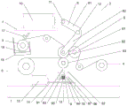
Fig. 1 is a schematic view of the overall structure of the present invention;
FIG. 2 is an enlarged view of a portion of FIG. 1 at A;
fig. 3 is a front view of the present invention.
In the figure: 1. a frame base; 2. a frame side plate; 3. a discharging roller; 4. a film roll; 5. a material receiving roller; 6. a film covering assembly; 61. a heating roller; 62. a first pressure roller; 63. a second pressure roller; 7. a support frame; 8. a movable arm; 81. a first movable arm; 82. a second movable arm; 9. an elastic member; 91. a movable post; 92. a limiting plate; 93. a movable column base; 94. a spring mount; 95. a spring; 96. a support pillar; 97. a spring cavity; 10. a first cylinder; 11. connecting blocks; 12. a pin shaft; 13. a slider; 14. a guide rail; 15. a second cylinder; 16. a guide rail locking device; 17. a blowing nozzle; 18. a dust collection box; 19. soaked with water sponge.
Detailed Description
The technical solutions in the embodiments of the present invention will be described clearly and completely with reference to fig. 1 to 3 of the embodiments of the present invention, and it is obvious that the described embodiments are only some embodiments of the present invention, not all embodiments. Based on the embodiments in the present invention, all other embodiments obtained by a person skilled in the art without creative efforts belong to the protection scope of the present invention.
Examples
As shown in fig. 1 to fig. 3, the utility model discloses a laminating machine applied to the production of embossment transfer paper, which comprises a frame base 1 and a frame side plate 2 connected to the frame base 1, wherein a discharging roller 3, a film roller 4, a laminating component 6 and a receiving roller 5 are arranged on the frame side plate 2, the discharging roller 3 is used for placing materials to be laminated, the film roller 4 is used for placing films, the laminating component 6 is used for combining the films and the materials, the receiving roller 5 is used for placing the laminated materials, wherein the laminating component 6 is arranged between the discharging roller 3 and the film roller 4, the laminating component 6 comprises a heating roller 61, a first pressure roller 62 and a second pressure roller 63, the first pressure roller 62 and the heating roller 61 are horizontally arranged, the heating roller 61 is arranged at one side close to the film roller 4, the second pressure roller 63 is arranged below the first pressure roller 62, be provided with support frame 7 on the frame curb plate 2, be equipped with first cylinder 10 on the support frame 7, be connected with connecting block 11 on the first cylinder 10, 11 both sides of connecting block all articulate there is the digging arm 8, the other end and the first pressure roller 62 of digging arm 8 are articulated mutually, the intermediate position hinged joint of digging arm 8 has round pin axle 12, round pin axle 12 is fixed on frame curb plate 2, be equipped with elastic component 9 on the frame base 1, elastic component 9 is connected with second pressure roller 63.
The utility model discloses at the during operation, first cylinder 10 drives connecting block 11 forward, connecting block 11 drives movable arm 8, it has round pin axle 12 of fixing on frame curb plate 2 to articulate in the middle of the movable arm 8, consequently, movable arm 8's upper end is just backward along with connecting block 11 forward while movable arm 8's lower extreme, consequently, first pressure roller 63 also can be backward, thereby make first pressure roller 63 keep away from second pressure roller 63 and warming mill 61, confirm the position with the material of treating the tectorial membrane on the ejection of compact roller 3 and the film on film roller 4 again and put into between first pressure roller 63 and the warming mill 61, pass again between first pressure roller 63 and the second pressure roller 64, later control first cylinder 10 back again and contract, make first pressure roller 63 compress tightly second pressure roller 64 and warming mill 61, then alright begin tectorial membrane work, the material of tectorial membrane completion is drawn into and is received material roller 5.
The movable arm 8 includes a first movable arm 81 and a second movable arm 82, an angle between the first movable arm 81 and the second movable arm 82 is 70 degrees to 90 degrees, the pin 12 is disposed between the first movable arm 81 and the second movable arm 82, and the angle facilitates the first pressure roller 62 to press the heating roller 61 and the second pressure roller 63 at an oblique downward angle when the first cylinder 10 retracts.
In addition, in order to enable the elastic member 9 to move, the spring base 94 on the elastic member 9 is connected with the guide rail 14 through the sliding block 13, and is controlled to move through the second air cylinder 15, and the second air cylinder 15 is installed on the frame base 1, so that the elastic member 9 drives the second pressure roller 63 to move, and the second pressure roller 63 is convenient to adjust the optimal pressing contact angle with the first pressure roller 62.
The guide rail 14 is provided with a guide rail locking device 16 on the side away from the cylinder, and the guide rail locking device 16 can lock the position of the elastic member 9 after the elastic member is positioned, so that the elastic member cannot move forwards any more, and the stability of the structure is enhanced.
In order to make the material of treating the tectorial membrane can keep clean getting into tectorial membrane subassembly 6, support frame 7 is provided with blowing nozzle 17 on the one side that is close to discharge roller 3, blowing nozzle 17 outwards inclines to set up in discharge roller 3 top, and blowing nozzle 17 can blow to the material of discharge roller 3 to reach the purpose of removing dust, reduce the production of dust alright reduce the bubble when tectorial membrane. In addition, in order to collect the blown dust, a dust box 18 is arranged on the frame, the dust box 18 is arranged around the discharging roller 3, and a water sponge 19 is arranged in the dust box 18 and used for adhering the dust.
The utility model that should point out simultaneously indicates the terminology, like: the directional or positional relationships indicated as "front", "rear", "vertical", "horizontal", etc. are based on the directional or positional relationships shown in the drawings, and are only for convenience of description and to simplify the description, but are not intended to indicate or imply that the device or element referred to must have a particular orientation, be constructed and operated in a particular orientation, and therefore should not be construed as limiting the scope of the invention.
The above description is only a preferred embodiment of the present invention, and should not be taken as limiting the invention, and any modifications, equivalent replacements, improvements, etc. made within the spirit and principle of the present invention should be included in the protection scope of the present invention.
Claims (7)
1. The utility model provides a be applied to laminating machine in relief (sculpture) transfer paper production, includes frame base (1) and frame curb plate (2) of connection on frame base (1), be equipped with discharge roller (3), film roller (4), tectorial membrane subassembly (6) and receipts material roller (5) on frame curb plate (2), its characterized in that: the film coating assembly (6) is arranged between the discharging roller (3) and the film roller (4), the film coating assembly (6) comprises a heating roller (61), a first pressure roller (62) and a second pressure roller (63), the first pressure roller (62) and the heating roller (61) are horizontally arranged, the heating roller (61) is arranged on one side close to the film roller (4), the second pressure roller (63) is arranged below the first pressure roller (62), a support frame (7) is arranged on the rack side plate (2), a first air cylinder (10) is arranged on the support frame (7), a connecting block (11) is arranged on the first air cylinder (10), movable arms (8) are hinged to two sides of the connecting block (11), the other ends of the movable arms (8) are hinged to the first pressure roller (62), and a pin shaft (12) is hinged to the middle position of the movable arms (8), the hinge pin (12) is fixed on the side plate (2) of the frame, the frame base (1) is provided with an elastic component (9), and the elastic component (9) is connected with a second pressure roller (63).
2. A laminating machine applied to the production of relief transfer paper according to claim 1, characterized in that: the movable arm (8) comprises a first movable arm (81) and a second movable arm (82), the setting angle of the first movable arm (81) and the second movable arm (82) is between 70 degrees and 90 degrees, and the pin shaft (12) is arranged between the first movable arm (81) and the second movable arm (82).
3. A laminating machine applied to the production of relief transfer paper according to claim 1, characterized in that: elastic component (9) is including activity post (91), limiting plate (92), activity post base (93) and spring base (94), be provided with a plurality of support columns (96) in the middle of limiting plate (92) and spring base (94), support column (96) separate limiting plate (92) and spring base (94) and are formed with spring chamber (97), spring base (94) are provided with a plurality of spring (95) in spring chamber (97), activity post base (93) set up in spring (95) top, activity post (91) are provided with two, connect respectively on the both ends of second pressure roller (63), the lower extreme of activity post (91) pierces through limiting plate (92) and connects on activity post base (93).
4. A laminating machine applied to the production of relief transfer paper according to claim 3, characterized in that: spring holder (94) below be equipped with slider (13), slider (13) have guide rail (14) down, be equipped with second cylinder (15) on frame base (1), second cylinder (15) are connected with spring holder (94).
5. A laminating machine applied to the production of relief transfer paper according to claim 4, characterized in that: and a guide rail locking device (16) is arranged on one side of the guide rail (14) far away from the cylinder.
6. A laminating machine applied to the production of relief transfer paper according to claim 1, characterized in that: and a blowing nozzle (17) is arranged on one surface of the support frame (7) close to the discharging roller (3), and the blowing nozzle (17) is obliquely arranged above the discharging roller (3) towards the outside.
7. A laminating machine applied to the production of relief transfer paper according to claim 6, characterized in that: the machine frame is provided with a dust collection box (18), the dust collection box (18) is arranged around the discharging roller (3), and a water-soaking sponge (19) is arranged in the dust collection box (18).
Priority Applications (1)
| Application Number | Priority Date | Filing Date | Title |
|---|---|---|---|
| CN201922300861.2U CN211567219U (en) | 2019-12-19 | 2019-12-19 | Be applied to laminating machine in relief (sculpture) transfer connects paper production |
Applications Claiming Priority (1)
| Application Number | Priority Date | Filing Date | Title |
|---|---|---|---|
| CN201922300861.2U CN211567219U (en) | 2019-12-19 | 2019-12-19 | Be applied to laminating machine in relief (sculpture) transfer connects paper production |
Publications (1)
| Publication Number | Publication Date |
|---|---|
| CN211567219U true CN211567219U (en) | 2020-09-25 |
Family
ID=72548871
Family Applications (1)
| Application Number | Title | Priority Date | Filing Date |
|---|---|---|---|
| CN201922300861.2U Active CN211567219U (en) | 2019-12-19 | 2019-12-19 | Be applied to laminating machine in relief (sculpture) transfer connects paper production |
Country Status (1)
| Country | Link |
|---|---|
| CN (1) | CN211567219U (en) |
Cited By (1)
| Publication number | Priority date | Publication date | Assignee | Title |
|---|---|---|---|---|
| CN112255065A (en) * | 2020-10-29 | 2021-01-22 | 南京英瀚斯生物科技有限公司 | Hydrogel membrane laminating device for multicellular ball culture |
-
2019
- 2019-12-19 CN CN201922300861.2U patent/CN211567219U/en active Active
Cited By (2)
| Publication number | Priority date | Publication date | Assignee | Title |
|---|---|---|---|---|
| CN112255065A (en) * | 2020-10-29 | 2021-01-22 | 南京英瀚斯生物科技有限公司 | Hydrogel membrane laminating device for multicellular ball culture |
| CN112255065B (en) * | 2020-10-29 | 2021-06-04 | 南京英瀚斯生物科技有限公司 | Hydrogel membrane laminating device for multicellular ball culture |
Similar Documents
| Publication | Publication Date | Title |
|---|---|---|
| CN211567219U (en) | Be applied to laminating machine in relief (sculpture) transfer connects paper production | |
| CN112496909A (en) | Plank surface machining processing apparatus | |
| CN213028745U (en) | Rigid-flex board pressfitting structure | |
| CN211594410U (en) | Electricity core unloader | |
| CN205386953U (en) | Automatic receive wall paper knurling cutting device of material | |
| CN113108601A (en) | High efficiency ferroelectric ceramic plate binder removal equipment | |
| CN207876820U (en) | A kind of presser type material fetching mechanism of heating furnace | |
| CN206344242U (en) | A kind of diaphragm die-cutting machine | |
| CN205467571U (en) | Wall paper knurling cutting device | |
| CN212287863U (en) | Ultra-thin aluminum foil forming machine | |
| CN207839686U (en) | A kind of bender | |
| CN212886034U (en) | Novel cell-phone screen equipment tool | |
| CN216337324U (en) | Laminated glass's apparatus for producing | |
| CN210082238U (en) | Calender for processing plastic products | |
| CN114179489A (en) | Production process and production device of laminated glass | |
| CN209465501U (en) | A kind of fold molding bending machine | |
| CN110817515A (en) | Biodegradable plastic film rolls up membrane device | |
| CN220243661U (en) | Laminating mechanism of 3D laminating machine | |
| CN214520467U (en) | Corrugated filtering layer trimming device | |
| CN211194902U (en) | Be used for EVA glued membrane production modular system | |
| CN220129001U (en) | Knee gasket mould | |
| CN214600124U (en) | A beat mucilage binding and put for gauze mask production | |
| CN218019137U (en) | Hydraulic forming equipment with digital display function for ceramic production | |
| CN108839334B (en) | Concave surface film covering head of 3D curved surface glass | |
| CN218114493U (en) | Waterproofing membrane production is with preventing fold device |
Legal Events
| Date | Code | Title | Description |
|---|---|---|---|
| GR01 | Patent grant | ||
| GR01 | Patent grant |