CN211564560U - Radial drilling machine applied to production of automobile stamping parts - Google Patents
Radial drilling machine applied to production of automobile stamping parts Download PDFInfo
- Publication number
- CN211564560U CN211564560U CN201922361518.9U CN201922361518U CN211564560U CN 211564560 U CN211564560 U CN 211564560U CN 201922361518 U CN201922361518 U CN 201922361518U CN 211564560 U CN211564560 U CN 211564560U
- Authority
- CN
- China
- Prior art keywords
- clamping
- production
- stamping parts
- stand
- base
- Prior art date
- Legal status (The legal status is an assumption and is not a legal conclusion. Google has not performed a legal analysis and makes no representation as to the accuracy of the status listed.)
- Active
Links
Images


Abstract
The utility model belongs to the technical field of the machine-building, especially, be applied to radial drill of automobile punching part production, including base, stand, rocking arm crossbearer, elevator motor, elevating screw, rocker arm guide rail, headstock, drill bit and spindle motor, the stand is fixed in top one side of base, the rocking arm crossbearer cup joints on the stand, the rocking arm crossbearer rotates with the stand to be connected, elevator motor installs in the top of stand, elevating screw parallel mount is in one side of elevating screw, elevator motor's output passes through the shaft coupling and is connected with elevating screw's one end. The utility model discloses can unify the clamping to a plurality of stamping parts, accomplish self-holding through die clamping cylinder simultaneously, realize the continuous processing of a plurality of stamping parts, satisfy the large-scale production processing demand, improve production efficiency, can realize concentrating the collection to clastic, avoid causing frock platform and ground pollution, guarantee going on of normal processing, and simple structure, convenient to use.
Description
Technical Field
The utility model relates to a machine-building technical field specifically is a radial drill who is applied to automobile punching part production.
Background
A radial drill is a drill in which a radial arm is rotatable and liftable around a column, and a spindle head is generally horizontally movable on the radial arm. When a hole is machined on a vertical drilling machine, the centering of a cutter and a workpiece is realized through the movement of the workpiece, so that the centering is obviously very inconvenient for some large and heavy workpieces; the radial drilling machine can be centered by the position of the movable tool shaft, which brings great convenience to processing holes on large and heavy workpieces in single-piece and small-batch production.
Radial drill machine uses extensively in the processing production in automobile punching part hole, but traditional radial drill machine single structure, has following defect:
1. the tool table of the traditional radial drilling machine can only clamp one stamping part at a time, cannot realize continuous processing of a plurality of stamping parts, cannot meet the requirement of large-scale production and processing, and has low processing efficiency;
2. lack effective sweeps and collect the mechanism, the piece that produces in the course of working is unrestrained at frock platform and subaerial, and accumulational piece causes the pollution to frock platform and ground, has influenced going on of normal processing simultaneously.
SUMMERY OF THE UTILITY MODEL
Technical problem to be solved
The utility model provides a not enough to prior art, the utility model provides a be applied to radial drill of automobile punching part production, the frock platform of having solved traditional radial drill can only clamping stamping workpiece once, can not realize the continuous processing of a plurality of stamping workpieces, can't satisfy large-scale production processing demand, machining efficiency is low, and lack effective sweeps and collect the mechanism, the piece that produces in the course of working is unrestrained at frock platform and subaerial, accumulational piece causes the pollution to frock platform and ground, the problem of going on of normal processing has been influenced simultaneously.
(II) technical scheme
In order to achieve the above object, the utility model provides a following technical scheme: the utility model provides a be applied to radial drill of automobile punching part production, includes base, stand, rocking arm crossbearer, elevator motor, elevating screw, rocking arm guide rail, headstock, drill bit and spindle motor, the stand is fixed in top one side of base, the rocking arm crossbearer cup joints on the stand, the rocking arm crossbearer rotates with the stand to be connected, elevator motor installs in the top of stand, elevating screw parallel mount is in one side of elevating screw, elevator motor's output passes through the shaft coupling and is connected with elevating screw's one end, elevating screw's the other end passes through screw nut and is connected with the rocking arm crossbearer, the rocking arm guide rail is violently arranged in on the rocking arm crossbearer, the output shaft end and the drill bit of headstock are connected, spindle motor installs in the top of headstock, spindle motor's output is connected with the input shaft.
The automatic feeding device is characterized in that an adjusting sliding groove is formed in the base, a bottom plate is arranged at the top of the base, an adjusting sliding block in sliding fit with the adjusting sliding groove is arranged at the bottom of the bottom plate, a linear lead screw guide rail is arranged at the top of the bottom plate, a sliding table is connected onto a lead screw nut of the linear lead screw guide rail, a material collecting mechanism is arranged on the sliding table and consists of a cabinet body and a drawing material collecting box, an opening matched with the drawing material collecting box is formed in one side wall of the cabinet body, a storage cavity for containing the drawing material collecting box is formed in the cabinet body, a tooling table is arranged at the top of the cabinet body, a plurality of blanking slots are arranged on the tooling table side by side, a feeding hole is formed in the top of the cabinet body and corresponds to the periphery of the tooling table and is provided with a feeding hole, a, Fixing base, die clamping cylinder and pinch-off blades are constituteed, the limiting plate correspondence sets up in the grooved one side of blanking, the fixing base correspondence sets up in the grooved opposite side of blanking, die clamping cylinder installs on the fixing base keeps away from the grooved lateral wall of blanking, die clamping cylinder's piston rod runs through the tip and the pinch-off blades fixed connection of fixing base, the position is equipped with the guide way that sets up perpendicularly with the blanking fluting under the corresponding pinch-off blades on the frock bench, pinch-off blades and guide way sliding fit.
As an optimized technical scheme of the utility model, the bottom of base is equipped with the shock pad foot.
As an optimized technical scheme of the utility model, be equipped with the handle on the pull collection box corresponds open-ended lateral wall.
As the utility model discloses a preferred technical scheme, all bond on the clamping face of limiting plate and pinch-off blades has the rubber gasket.
As an optimal technical scheme of the utility model, be equipped with the locking screw on the both ends wall around the bottom plate, the both sides correspondence that corresponds the regulation spout on the base is equipped with the location screw, location screw and locking screw are in on the coplanar, be connected through set screw between locking screw and the location screw.
(III) advantageous effects
Compared with the prior art, the utility model provides a be applied to radial drill of automobile punching part production possesses following beneficial effect:
1. this be applied to radial drill of automobile punching part production can unify the clamping to a plurality of stamping parts, accomplishes self-holding simultaneously through die clamping cylinder, under the clearance progressive feed cooperation of linear lead screw guide rail, realizes the continuous processing of a plurality of stamping parts, satisfies extensive production and processing demand, has improved production efficiency.
2. This be applied to radial drill of automobile punching part production through setting up the mechanism that gathers materials in frock platform bottom, in the piece that produces passes through the feed inlet and gets into the pull collecting box in the course of working, can realize gathering the collection to clastic concentration, avoid causing frock platform and ground pollution, guaranteed going on of normal processing, and simple structure, convenient to use.
Drawings
Fig. 1 is a schematic structural view of the present invention;
FIG. 2 is a schematic view of the connection structure of the material collecting mechanism, the tooling table and the clamping mechanism of the present invention;
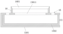
FIG. 3 is a cross-sectional view of the material collecting mechanism and the tooling table;
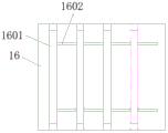
fig. 4 is a top view of the middle tooling table of the present invention.
In the figure: 1. a base; 2. a column; 3. a rocker arm cross frame; 4. a lifting motor; 5. lifting a screw rod; 6. a rocker arm guide rail; 7. a main spindle box; 8. a drill bit; 9. a spindle motor; 10. adjusting the sliding chute; 11. a base plate; 12. adjusting the sliding block; 13. a linear lead screw guide rail; 14. a sliding table; 15. a material collecting mechanism; 1501. a cabinet body; 15011. a feed inlet; 1502. drawing the material collecting box; 16. a tooling table; 1601. blanking and slotting; 1602. a guide groove; 17. a clamping mechanism; 1701. a limiting plate; 1702. a fixed seat; 1703. a clamping cylinder; 1704. a clamping plate; 18. positioning the screw hole; 19. and (5) positioning the screw.
Detailed Description
The technical solutions in the embodiments of the present invention will be described clearly and completely with reference to the accompanying drawings in the embodiments of the present invention, and it is obvious that the described embodiments are only some embodiments of the present invention, not all embodiments. Based on the embodiments in the present invention, all other embodiments obtained by a person skilled in the art without creative work belong to the protection scope of the present invention.
Examples
Referring to fig. 1-4, the present invention provides the following technical solutions: a radial drilling machine applied to the production of automobile stamping parts comprises a base 1, a stand column 2, a radial cross frame 3 and a lifting motor 4, elevating screw 5, rocker arm guide rail 6, headstock 7, drill bit 8 and spindle motor 9, stand 2 is fixed in top one side of base 1, rocker arm crossbearer 3 cup joints on stand 2, rocker arm crossbearer 3 rotates with stand 2 to be connected, elevating motor 4 installs on the top of stand 2, elevating screw 5 parallel mount is in one side of elevating screw 5, elevating motor 4's output passes through the shaft coupling and is connected with elevating screw 5's one end, elevating screw 5's the other end passes through screw nut and is connected with rocker arm crossbearer 3, rocker arm guide rail 6 is violently arranged on rocker arm crossbearer 3, the output shaft end of headstock 7 is connected with drill bit 8, spindle motor 9 installs at the top of headstock 7, spindle motor 9's output is connected with the input shaft end of headstock 7.
An adjusting chute 10 is arranged on a base 1, a bottom plate 11 is arranged on the top of the base 1, an adjusting slide block 12 which is in sliding fit with the adjusting chute 10 is arranged at the bottom of the bottom plate 11, a linear lead screw guide rail 13 is arranged on the top of the bottom plate 11, a sliding table 14 is connected on a lead screw nut of the linear lead screw guide rail 13, a material collecting mechanism 15 is arranged on the sliding table 14, the material collecting mechanism 15 is composed of a cabinet body 1501 and a drawing material collecting box 1502, an opening which is matched with the drawing material collecting box 1502 is arranged on one side wall of the cabinet body 1501, a storage cavity which contains the drawing material collecting box 1502 is arranged in the cabinet body 1501, a tooling table 16 is arranged on the top of the cabinet body 1501, a plurality of blanking slots 1601 are arranged on the tooling table 16 side by side, a feeding hole 15011 is arranged on the top of the cabinet body 1501 corresponding to the periphery, the clamping mechanism 17 is composed of a limiting plate 1701, a fixing seat 1702, a clamping cylinder 1703 and a clamping plate 1704, the limiting plate 1701 is correspondingly arranged on one side of the blanking slot 1601, the fixing seat 1702 is correspondingly arranged on the other side of the blanking slot 1601, the clamping cylinder 1703 is arranged on the side wall of the fixing seat 1702 far away from the blanking slot 1601, a piston rod of the clamping cylinder 1703 penetrates through the end part of the fixing seat 1702 and is fixedly connected with the clamping plate 1704, a guide groove 1602 which is perpendicular to the blanking slot 1601 is arranged on the position, right below the clamping plate 1704, on the tooling table 16, and the clamping plate 1704 is in sliding fit with the guide groove 1602.
In the embodiment, the radial drill applied to the production of automobile stamping parts further comprises a controller, a plurality of control buttons and a positioning sensing assembly for positioning a workpiece to be machined, wherein the controller is respectively electrically connected with the lifting motor 4, the spindle motor 9, a driving motor of the linear lead screw guide rail 13, the clamping cylinder 1703, the control buttons and the positioning sensing assembly, the controller adopts an 80C51 single chip microcomputer, the positioning sensing assembly adopts an infrared laser positioning sensor, the infrared laser positioning sensor consists of an infrared laser transmitter arranged on one side of the drill bit 8 and an infrared laser receiver arranged on the tooling table 16, the laser transmitter corresponds to the laser receiver up and down, infrared rays emitted by the infrared laser transmitter are received by the infrared laser receiver, the infrared laser receiver transmits information to the controller after receiving the infrared rays, and the controller controls the linear lead screw guide rail 13 to stop running, at the moment, the workpiece to be machined is located right below the drill bit 8, and then machining can be performed through the drill bit 8, the control buttons are used for controlling the working state of the radial drilling machine, for example, whether the lifting motor 4 drives the rocker cross frame 3 to lift or not can be controlled through the corresponding control buttons, whether the spindle motor 9 drives the drill bit 8 to work or not can be controlled through the corresponding control buttons, and the like; in the utility model, the rocker guide 6 of the utility model can be a linear automatic guide, the structure of which can be consistent with the structure of the linear lead screw guide 13, and the lead screw transmission guide structure in the prior art is adopted to realize automatic control; the number of the blanking slots 1601 is different from 4, 5, 6 and 7, so that 4, 5, 6 and 7 different workpieces to be processed can be continuously processed, and the purpose of improving the processing efficiency is achieved; the utility model discloses well pull box 1502 that gathers materials is equipped with open box body, the feeding of being convenient for the top.
Specifically, the bottom of the base 1 is provided with a shock pad.
In this embodiment, the shock pad foot can adopt rubber shock pad board, can provide the buffering in equipment course of working, guarantees the stability of drilling machine.
Specifically, a handle is arranged on one side wall of the drawing aggregate box 1502 corresponding to the opening.
In this embodiment, the drawable aggregate box 1502 is drawn out to the outside of the cabinet 1501 through the drawable handle, so that the scraps in the drawable aggregate box 1502 can be treated.
Specifically, rubber gaskets are bonded to the sandwiching surfaces of the stopper plate 1701 and the clamp plate 1704.
In this embodiment, the setting of rubber gasket can treat the machined part and play the effect that prevents the surperficial fish tail of work piece.
Specifically, the front end wall and the rear end wall of the bottom plate 11 are provided with locking screw holes, the two sides of the base 1 corresponding to the adjusting sliding grooves 10 are correspondingly provided with positioning screw holes 18, the positioning screw holes 18 and the locking screw holes are positioned on the same vertical plane, and the locking screw holes are connected with the positioning screw holes 18 through positioning screws 19.
In this embodiment, during the use, through loosening set screw 19, promote bottom plate 11 along adjusting spout 10, drive the frock platform 16 on the bottom plate 11 and move and adjust to treating that the machined part is in the corresponding position that needs to punch, rethread set screw 19 fastens bottom plate 11 on base 1, accomplishes the locking of frock platform 16.
The utility model discloses a theory of operation and use flow: when the device is used, a corresponding number of workpieces to be machined are placed on the blanking slot 1601 one by one, the clamping cylinder 1703 is controlled to work, the piston rod of the clamping cylinder 1703 drives the clamping plate 1704 to slide along the guide slot 1602 to clamp the workpieces to be machined, the positioning screw 19 is loosened, the bottom plate 11 is pushed along the adjusting chute 10 to drive the tool table 16 on the bottom plate 11 to move and adjust to the corresponding position of the workpieces to be machined, the bottom plate 11 is fastened on the base 1 through the positioning screw 19 to complete the locking of the tool table 16, the positions of the spindle box 7 and the drill bit 8 are adjusted through the rocker guide rail 6, the drill bit 8 is adjusted to be above the position to be machined, the linear lead screw guide rail 13 is controlled to run, the aggregate mechanism 15, the tool table 16 and the workpieces to be machined on the spindle table are driven to linearly move along the guide rail by the sliding table 14, and the driving motor of the linear lead screw guide rail 13, then, a spindle motor 9 is started, a drill bit 8 is driven to rotate through the spindle motor 9 and a spindle box 7, the rocker arm cross frame 3 is driven to descend through the cooperation of a lifting motor 4 and a lifting screw 5, workpieces to be machined are machined through the drill bit 8, the drill bit 8 resets after machining is completed, a linear screw guide rail 13 continues to work, a tool table 16 and workpieces to be machined on the tool table are driven to continue to move, when workpieces to be machined are located under the drill bit 8, the drill bit 8 is driven to rotate through the spindle motor 9 and the spindle box 7, the rocker arm cross frame 3 descends through the cooperation of the lifting motor 4 and the lifting screw 5, the workpieces to be machined are machined through the drill bit 8, and the operation is repeated until all the workpieces to be machined are machined, continuous machining is achieved, and the purpose of improving production efficiency is achieved; treat that the piece that produces in the machined part course of working passes through blanking slot 1601 and feed inlet 15011 and gets into the pull box 1502 that gathers materials, can take out the pull box 1502 through the pull handle, accomplish the piece and collect, be convenient for simultaneously handle.
Finally, it should be noted that: although the present invention has been described in detail with reference to the foregoing embodiments, it will be apparent to those skilled in the art that modifications may be made to the embodiments described in the foregoing embodiments, or equivalents may be substituted for elements thereof. Any modification, equivalent replacement, or improvement made within the spirit and principle of the present invention should be included in the protection scope of the present invention.
Claims (5)
1. The utility model provides a radial drill who is applied to automobile punching part production which characterized in that: comprises a base (1), a column (2), a rocker cross frame (3), a lifting motor (4), a lifting screw (5), a rocker guide rail (6), a spindle box (7), a drill bit (8) and a spindle motor (9), wherein the column (2) is fixed on one side of the top of the base (1), the rocker cross frame (3) is sleeved on the column (2), the rocker cross frame (3) is rotatably connected with the column (2), the lifting motor (4) is arranged at the top end of the column (2), the lifting screw (5) is parallelly arranged on one side of the lifting screw (5), the output end of the lifting motor (4) is connected with one end of the lifting screw (5) through a shaft coupler, the other end of the lifting screw (5) is connected with the rocker cross frame (3) through a screw nut, the rocker guide rail (6) is transversely arranged on the rocker cross frame (3), the output shaft end of the spindle box (7) is connected with the drill bit (8), the spindle motor (9) is arranged at the top of the spindle box (7), and the output end of the spindle motor (9) is connected with the input shaft end of the spindle box (7);
the utility model discloses a material collecting cabinet, including base (1), bottom plate (11), linear lead screw guide rail (13), slip table (14), be equipped with on slip table (14) and gather materials mechanism (15), gather materials mechanism (15) and constitute by the cabinet body (1501) and pull material collecting box (1502), be equipped with the opening with pull material collecting box (1502) looks adaptation on one side wall of the cabinet body (1501), the inside of the cabinet body (1501) is equipped with the thing chamber of holding pull material collecting box (1502), the top of the cabinet body (1501) is equipped with frock platform (16), be equipped with a plurality of blanking fluting (1601) on frock platform (16) side by side, the top of the cabinet body (1501) corresponds to the periphery of a tooling platform (16) and the lower part of the blanking slot (1601) is provided with a feed inlet (15011), the tooling platform (16) is provided with a clamping mechanism (17) which has the same number with the blanking slot (1601) and is used for automatically clamping a workpiece to be machined, the clamping mechanism (17) consists of a limiting plate (1701), a fixed seat (1702), a clamping cylinder (1703) and a clamping plate (1704), the limiting plate (1701) is correspondingly arranged on one side of the blanking slot (1601), the fixed seat (1702) is correspondingly arranged on the other side of the blanking slot (1601), the clamping cylinder (1703) is arranged on the side wall of the fixed seat (1702) far away from the blanking slot (1601), the piston rod of the clamping cylinder (1703) penetrates through the end part of the fixed seat (1702) and is fixedly connected with the clamping plate (1704), and a guide slot (1602) which is vertically arranged with the blanking slot (1601) is arranged at a position right below the clamping plate (, the clamping plate (1704) is in sliding fit with the guide groove (1602).
2. The radial drilling machine applied to the production of automobile stamping parts according to claim 1, characterized in that: the bottom of the base (1) is provided with a shock pad foot.
3. The radial drilling machine applied to the production of automobile stamping parts according to claim 1, characterized in that: a handle is arranged on one side wall of the drawing material collecting box (1502) corresponding to the opening.
4. The radial drilling machine applied to the production of automobile stamping parts according to claim 1, characterized in that: rubber gaskets are bonded on the clamping surfaces of the limiting plate (1701) and the clamping plate (1704).
5. The radial drilling machine applied to the production of automobile stamping parts according to claim 1, characterized in that: the front end wall and the rear end wall of the bottom plate (11) are provided with locking screw holes, two sides of the base (1) corresponding to the adjusting sliding grooves (10) are correspondingly provided with positioning screw holes (18), the positioning screw holes (18) and the locking screw holes are located on the same vertical plane, and the locking screw holes are connected with the positioning screw holes (18) through positioning screws (19).
Priority Applications (1)
| Application Number | Priority Date | Filing Date | Title |
|---|---|---|---|
| CN201922361518.9U CN211564560U (en) | 2019-12-24 | 2019-12-24 | Radial drilling machine applied to production of automobile stamping parts |
Applications Claiming Priority (1)
| Application Number | Priority Date | Filing Date | Title |
|---|---|---|---|
| CN201922361518.9U CN211564560U (en) | 2019-12-24 | 2019-12-24 | Radial drilling machine applied to production of automobile stamping parts |
Publications (1)
| Publication Number | Publication Date |
|---|---|
| CN211564560U true CN211564560U (en) | 2020-09-25 |
Family
ID=72549146
Family Applications (1)
| Application Number | Title | Priority Date | Filing Date |
|---|---|---|---|
| CN201922361518.9U Active CN211564560U (en) | 2019-12-24 | 2019-12-24 | Radial drilling machine applied to production of automobile stamping parts |
Country Status (1)
| Country | Link |
|---|---|
| CN (1) | CN211564560U (en) |
Cited By (1)
| Publication number | Priority date | Publication date | Assignee | Title |
|---|---|---|---|---|
| CN114669776A (en) * | 2022-04-02 | 2022-06-28 | 安徽宝立华机械设备有限公司 | Hole opening device of high-pressure valve |
-
2019
- 2019-12-24 CN CN201922361518.9U patent/CN211564560U/en active Active
Cited By (1)
| Publication number | Priority date | Publication date | Assignee | Title |
|---|---|---|---|---|
| CN114669776A (en) * | 2022-04-02 | 2022-06-28 | 安徽宝立华机械设备有限公司 | Hole opening device of high-pressure valve |
Similar Documents
| Publication | Publication Date | Title |
|---|---|---|
| CN211564560U (en) | Radial drilling machine applied to production of automobile stamping parts | |
| CN215319241U (en) | A milling flutes chasing bar that punches for wood working | |
| CN212885235U (en) | Drilling machine capable of achieving multidirectional punching | |
| CN211221100U (en) | Efficient punching equipment for umbrella handle | |
| CN210877599U (en) | A turning equipment of adjusting in convenient for machining | |
| CN214640577U (en) | Efficient semi-automatic cutting machine device | |
| CN212287979U (en) | A keyway planer for pencil processing | |
| CN205798488U (en) | The efficient drilling machine that a kind of machining is special | |
| CN112388327B (en) | Raised nonstop edging equipment in surface groove for metal product production | |
| CN209364081U (en) | A kind of antenna for base station automatic counterboring tapping equipment | |
| CN209206527U (en) | A kind of waste material cleaning machine of boring machine | |
| CN210877825U (en) | Automatic broach loosening device of vertical lathe | |
| CN209793094U (en) | Milling and boring double-function machine | |
| CN209551209U (en) | A kind of processing of high effective portable attacks tooling with brill | |
| CN208033716U (en) | A kind of mold drilling equipment | |
| CN112122643A (en) | Numerical control automatic feeding double-row drilling machine | |
| CN217702552U (en) | Milling device with low-consumption conveying space limiting structure | |
| CN210387815U (en) | Linear groove grooving machine for long-strip-shaped rod body | |
| CN211588609U (en) | Boring device for flange machining | |
| CN217393960U (en) | Cutting machine for bevel angle cutting of tooth head | |
| CN220499572U (en) | Gantry type single-station triaxial glass drilling machine box mechanism | |
| CN211162034U (en) | Device for drilling supporting piece | |
| CN208744236U (en) | A kind of multistation valve body perforation processing center | |
| CN215998304U (en) | Numerical control lathe processing structure of punching a hole | |
| CN210877641U (en) | Shaft type rough and fine drilling integrated numerical control drilling machine |
Legal Events
| Date | Code | Title | Description |
|---|---|---|---|
| GR01 | Patent grant | ||
| GR01 | Patent grant |