CN211563077U - Reducing mechanism is used in concrete block recovery - Google Patents
Reducing mechanism is used in concrete block recovery Download PDFInfo
- Publication number
- CN211563077U CN211563077U CN201922025479.5U CN201922025479U CN211563077U CN 211563077 U CN211563077 U CN 211563077U CN 201922025479 U CN201922025479 U CN 201922025479U CN 211563077 U CN211563077 U CN 211563077U
- Authority
- CN
- China
- Prior art keywords
- fixedly connected
- crushing
- box
- box body
- gear
- Prior art date
- Legal status (The legal status is an assumption and is not a legal conclusion. Google has not performed a legal analysis and makes no representation as to the accuracy of the status listed.)
- Expired - Fee Related
Links
- 238000011084 recovery Methods 0.000 title abstract description 6
- 238000012216 screening Methods 0.000 claims abstract description 12
- 239000000428 dust Substances 0.000 claims description 12
- 238000004064 recycling Methods 0.000 claims description 6
- 239000000463 material Substances 0.000 claims description 5
- 229920000297 Rayon Polymers 0.000 claims description 3
- 229920005549 butyl rubber Polymers 0.000 claims description 3
- 239000003292 glue Substances 0.000 claims description 3
- 230000000694 effects Effects 0.000 abstract description 5
- 238000005192 partition Methods 0.000 description 6
- 238000010298 pulverizing process Methods 0.000 description 4
- 239000008187 granular material Substances 0.000 description 2
- 238000000034 method Methods 0.000 description 2
- BPQQTUXANYXVAA-UHFFFAOYSA-N Orthosilicate Chemical compound [O-][Si]([O-])([O-])[O-] BPQQTUXANYXVAA-UHFFFAOYSA-N 0.000 description 1
- 230000004075 alteration Effects 0.000 description 1
- 230000009286 beneficial effect Effects 0.000 description 1
- 239000011449 brick Substances 0.000 description 1
- 239000011083 cement mortar Substances 0.000 description 1
- 239000004927 clay Substances 0.000 description 1
- 239000003245 coal Substances 0.000 description 1
- 230000007613 environmental effect Effects 0.000 description 1
- 238000002474 experimental method Methods 0.000 description 1
- 239000010881 fly ash Substances 0.000 description 1
- 238000012986 modification Methods 0.000 description 1
- 230000004048 modification Effects 0.000 description 1
- 239000002245 particle Substances 0.000 description 1
- 239000002994 raw material Substances 0.000 description 1
- 239000002893 slag Substances 0.000 description 1
- 238000006467 substitution reaction Methods 0.000 description 1
- 239000002699 waste material Substances 0.000 description 1
Images


Landscapes
- Crushing And Grinding (AREA)
Abstract
The utility model discloses a reducing mechanism is used in concrete block recovery, the power distribution box comprises a box body, the left end fixedly connected with cylinder at box top, the right-hand member fixedly connected with connecting rod of cylinder, the piece is smashed to the bottom fixedly connected with of connecting rod, smash the piece about the equal fixedly connected with second in both ends and smash the tooth, the first tooth of smashing of the equal fixedly connected with in upper end of the inner chamber of the box left and right sides, the upper end fixedly connected with baffle of inner chamber of the box, the screening hole has been seted up to the middle-end of baffle internal surface. The utility model discloses a cylinder, connecting rod, crushing piece, first crushing tooth, screening hole, the effect that the roller was smashed to the second, motor, first gear, first rotary rod, first crushing roller, second gear, second rotary rod and second have reached and have smashed effectual demand, and it is poor to have solved current reducing mechanism crushing effect, smashes not thoroughly, influences the recovery of building block, has reduced the problem of crushing efficiency.
Description
Technical Field
The utility model relates to a building technical field specifically is a concrete block retrieves and uses reducing mechanism.
Background
The building block is a massive building product which is larger than a clay brick body, has wide raw material sources and a plurality of varieties, can be obtained from local materials and has low price, the building blocks are divided into building blocks such as concrete, cement mortar, aerated concrete, fly ash silicate, coal gangue, artificial ceramsite, slag waste and the like according to the materials, and can be used as a bearing wall and a partition wall.
SUMMERY OF THE UTILITY MODEL
An object of the utility model is to provide a concrete block retrieves and uses reducing mechanism to solve the problem that proposes among the above-mentioned background art.
In order to achieve the above object, the utility model provides a following technical scheme: a crushing device for recycling concrete blocks comprises a box body, wherein a cylinder is fixedly connected to the left end of the top of the box body, a connecting rod is fixedly connected to the right end of the cylinder, a crushing block is fixedly connected to the bottom of the connecting rod, second crushing teeth are fixedly connected to the left end and the right end of the crushing block, first crushing teeth are fixedly connected to the upper ends of the left side and the right side of the inner cavity of the box body, a partition plate is fixedly connected to the upper end of the inner cavity of the box body, a screening hole is formed in the middle end of the inner surface of the partition plate, a mounting plate is fixedly connected to the lower end of the left side of the back of the box body, a motor is fixedly mounted at the top of the mounting plate, a first gear is fixedly connected to the output shaft of the motor, a first rotating rod is fixedly connected to the middle end of the front of the first gear, a, the positive middle-end fixedly connected with second rotary rod of second gear, the front end fixedly connected with second crushing roller of second rotary rod surface.
Preferably, the periphery of the bottom of the box body is fixedly connected with supporting legs, and the bottoms of the supporting legs are connected with butyl rubber pads through viscose glue.
Preferably, a fan is fixedly mounted at the middle end of the right side of the box body, the air outlet end of the fan is communicated with the lower end of the right side of the dust collection box through a pipeline, and the air inlet end of the fan is communicated with the upper end of the right side of the box body through a pipeline.
Preferably, the right end of the top of the box body is provided with a sliding chute, and an inner cavity of the sliding chute is connected with a connecting rod in a sliding manner.
Preferably, the left end and the right end of the top of the box body are communicated with the bottom of the funnel, and the left end and the right end of the bottom of the inner cavity of the box body are fixedly connected with the material guide blocks.
Compared with the prior art, the beneficial effects of the utility model are as follows:
1. the utility model is provided with a cylinder, a connecting rod, a crushing block, a first crushing tooth, a screening hole and a second crushing tooth, people put the building block into a box body through a funnel, then the cylinder is controlled to expand through an external controller, the cylinder can drive the connecting rod to move left and right while expanding, the connecting rod can drive the second crushing tooth on the crushing block to move left and right while moving left and right, the second crushing tooth is matched with the first crushing tooth, so that the large building block is crushed into small building blocks, the small building blocks enter the lower end of the box body from the screening hole, thereby achieving the purpose of first-stage crushing, the utility model is provided with a motor, a first gear, a first external rotary rod, a first crushing roller, a second gear, a second rotary rod and a second crushing roller, people open the motor through the external controller, the motor can drive the first gear to rotate, the first gear can drive the first rotary rod and the second gear to rotate when rotating, first rotary rod can drive first crushing roller when the pivoted and rotate, the second gear can drive the second rotary rod when the pivoted and rotate, the second rotary rod can drive the second when the pivoted and smash the roller and rotate, the cooperation of second crushing roller and first crushing roller, make small-size building block smash into the granule, thereby the kibbling purpose of second level has been reached, cooperation through above structure, the effectual demand of smashing has been reached, it is poor to have solved current reducing mechanism crushing effect, smash not thorough, influence the recovery of building block, the problem of crushing efficiency has been reduced.
2. The utility model discloses set up fan and dust collection box, people open the fan through external controller, and the fan can be transported the dust that produces among the crushing process and store in the dust collection box to the purpose of environmental protection has been reached.
Drawings
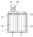
FIG. 1 is a schematic front view of the present invention;
FIG. 2 is a left side view of the structure of the present invention;
fig. 3 is a schematic view of the internal structure of the present invention in a top view.
In the figure: 1. a box body; 2. a first rotating rod; 3. a material guide block; 4. supporting legs; 5. a partition plate; 6. a first crushing tooth; 7. crushing the blocks; 8. a cylinder; 9. a connecting rod; 10. a chute; 11. a funnel; 12. a second crushing tooth; 13. a screening well; 14. a fan; 15. a second crushing roller; 16. a dust collection box; 17. a second rotating rod; 18. a first crushing roller; 19. mounting a plate; 20. a motor; 21. a first gear; 22. a second gear.
Detailed Description
The technical solutions in the embodiments of the present invention will be described clearly and completely with reference to the accompanying drawings in the embodiments of the present invention, and it is obvious that the described embodiments are only some embodiments of the present invention, not all embodiments. Based on the embodiments in the present invention, all other embodiments obtained by a person skilled in the art without creative work belong to the protection scope of the present invention.
In the description of the present invention, it is to be noted that, unless otherwise explicitly specified or limited, the terms "mounted", "provided", "connected", and the like are to be construed broadly, such as "connected", which may be fixedly connected, detachably connected, or integrally connected; can be mechanically or electrically connected; they may be connected directly or indirectly through intervening media, or they may be interconnected between two elements. The specific meaning of the above terms in the present invention can be understood in specific cases to those skilled in the art.
The utility model discloses a box 1, first rotary rod 2, guide block 3, supporting leg 4, baffle 5, first crushing tooth 6, smash piece 7, cylinder 8, connecting rod 9, spout 10, funnel 11, second crushing tooth 12, screening hole 13, fan 14, second crushing roller 15, dust collection box 16, second rotary rod 17, first crushing roller 18, mounting panel 19, motor 20, first gear 21 and second gear 22 part are the parts that universal standard spare or technical personnel in the field know, its structure and principle all are that this technical staff all can learn through the technical manual or learn through conventional experimental method.
Referring to fig. 1-3, a concrete block recycling crushing device comprises a box body 1, a cylinder 8 is fixedly connected to the left end of the top of the box body 1, a connecting rod 9 is fixedly connected to the right end of the cylinder 8, a crushing block 7 is fixedly connected to the bottom of the connecting rod 9, second crushing teeth 12 are fixedly connected to the left end and the right end of the crushing block 7, first crushing teeth 6 are fixedly connected to the upper ends of the left side and the right side of the inner cavity of the box body 1, a partition plate 5 is fixedly connected to the upper end of the inner cavity of the box body 1, a screening hole 13 is formed in the middle end of the inner surface of the partition plate 5, people put the concrete block into the box body 1 through a funnel 11, then the cylinder 8 is controlled to stretch through an external controller, the cylinder 8 can drive the connecting rod 9 to move left and right while stretching, the connecting rod 9 can drive the second crushing teeth 12 on the crushing block 7, the large building blocks are crushed into small building blocks, the small building blocks enter the lower end of a box body 1 from a screening hole 13, so that the purpose of primary crushing is achieved, a mounting plate 19 is fixedly connected to the lower end of the left side of the back of the box body 1, supporting legs 4 are fixedly connected to the periphery of the bottom of the box body 1, butyl rubber pads are connected to the bottoms of the supporting legs 4 through viscose glue, a chute 10 is formed in the right end of the top of the box body 1, a connecting rod 9 is connected to the inner cavity of the chute 10 in a sliding manner, the left end and the right end of the top of the box body 1 are communicated with the bottom of a funnel 11, guide blocks 3 are fixedly connected to the left end and the right end of the inner cavity of the box body 1, a fan 14 is fixedly mounted at the middle end of the right side of the box body 1, the, the fan 14 can transport the dust generated in the pulverizing process to the dust collecting box 16 for storage, thereby achieving the purpose of protecting the environment, the top of the mounting plate 19 is fixedly provided with a motor 20, the output shaft of the motor 20 is fixedly connected with a first gear 21, the front middle end of the first gear 21 is fixedly connected with a first rotating rod 2, the front end of the outer surface of the first rotating rod 2 is fixedly connected with a first pulverizing roller 18, the right end of the first gear 21 is connected with a second gear 22 in a meshing manner, the front middle end of the second gear 22 is fixedly connected with a second rotating rod 17, the front end of the outer surface of the second rotating rod 17 is fixedly connected with a second pulverizing roller 15, people turn on the motor 20 through an external controller, the motor 20 can drive the first gear 21 to rotate, the first gear 21 can drive the first rotating rod 2 and the second gear 22 to rotate while rotating, the first rotating rod 2 can drive the first pulverizing roller 18 to rotate while rotating, second gear 22 can drive second rotary rod 17 and rotate when the pivoted, second rotary rod 17 can drive second crushing roller 15 and rotate when the pivoted, second crushing roller 15 and first crushing roller 18's cooperation makes small-size building block smash into the granule, thereby reached the kibbling purpose of second level (the model of external control ware is DATA-7311 in this application, simultaneously, two wiring ends of external control ware are connected with power plug through the wire, and adopt the commercial power to supply power in this application).
When the device is used, the air cylinder 8, the connecting rod 9, the crushing block 7, the first crushing tooth 6, the screening hole 13 and the second crushing tooth 12 are arranged, people put the building blocks into the box body 1 through the funnel 11, then the air cylinder 8 is controlled to stretch through the external controller, the air cylinder 8 can drive the connecting rod 9 to move left and right while stretching, the connecting rod 9 can drive the second crushing tooth 12 on the crushing block 7 to move left and right while moving left and right, the second crushing tooth 12 is matched with the first crushing tooth 6, so that large building blocks are crushed into small building blocks, the small building blocks enter the lower end of the box body 1 from the screening hole 13, the purpose of primary crushing is achieved, the motor 20, the first gear 21, the first rotating rod 2, the first crushing roller 18, the second gear 22, the second rotating rod 17 and the second crushing roller 15 are arranged, people open the motor 20 through the external controller, and the motor 20 can drive the first gear 21 to rotate, the first gear 21 can drive the first rotating rod 2 and the second gear 22 to rotate when rotating, the first rotating rod 2 can drive the first crushing roller 18 to rotate when rotating, the second gear 22 can drive the second rotating rod 17 to rotate when rotating, the second rotating rod 17 can drive the second crushing roller 15 to rotate when rotating, the second crushing roller 15 is matched with the first crushing roller 18, so that small-sized building blocks are crushed into particles, the purpose of secondary crushing is achieved, through the matching of the above structures, the requirement of good crushing effect is achieved, the problems that the existing crushing device is poor in crushing effect, the crushing is incomplete, the recovery of building blocks is influenced, and the crushing efficiency is reduced are solved, the fan 14 and the dust box 16 are arranged, people open the fan 14 through an external controller, and the fan 14 can transport dust generated in the crushing process to the dust box 16 for storage, thereby achieving the purpose of protecting the environment.
Although embodiments of the present invention have been shown and described, it will be appreciated by those skilled in the art that changes, modifications, substitutions and alterations can be made in these embodiments without departing from the principles and spirit of the invention, the scope of which is defined in the appended claims and their equivalents.
Claims (5)
1. The utility model provides a concrete block retrieves and uses reducing mechanism, includes box (1), its characterized in that: the left end fixedly connected with cylinder (8) at box (1) top, the right-hand member fixedly connected with connecting rod (9) of cylinder (8), the bottom fixedly connected with of connecting rod (9) smashes piece (7), the equal fixedly connected with second of the left and right sides of smashing piece (7) smashes tooth (12), the equal fixedly connected with first crushing tooth (6) of upper end at the box (1) inner chamber left and right sides, the upper end fixedly connected with baffle (5) of box (1) inner chamber, the middle-end of baffle (5) internal surface has seted up screening hole (13), the left lower extreme fixedly connected with mounting panel (19) in box (1) back, the top fixed mounting of mounting panel (19) has motor (20), the output shaft fixedly connected with first gear (21) of motor (20), the positive middle-end fixedly connected with first rotary rod (2) of first gear (21), the front end fixedly connected with of first rotary rod (2) surface smashes roller (18), the right-hand member meshing of first gear (21) is connected with second gear (22), the positive middle-end fixedly connected with second rotary rod (17) of second gear (22), the front end fixedly connected with second of second rotary rod (17) surface smashes roller (15).
2. A crushing apparatus for concrete block recycling according to claim 1, characterized in that: the box body (1) is characterized in that supporting legs (4) are fixedly connected to the periphery of the bottom of the box body (1), and butyl rubber pads are connected to the bottoms of the supporting legs (4) through viscose glue.
3. A crushing apparatus for concrete block recycling according to claim 1, characterized in that: the middle end of the right side of the box body (1) is fixedly provided with a fan (14), the air outlet end of the fan (14) is communicated with the lower end of the right side of the dust collection box (16) through a pipeline, and the air inlet end of the fan (14) is communicated with the upper end of the right side of the box body (1) through a pipeline.
4. A crushing apparatus for concrete block recycling according to claim 1, characterized in that: the right end of the top of the box body (1) is provided with a sliding chute (10), and an inner cavity of the sliding chute (10) is connected with a connecting rod (9) in a sliding manner.
5. A crushing apparatus for concrete block recycling according to claim 1, characterized in that: the hopper is characterized in that the left end and the right end of the top of the box body (1) are communicated with the bottom of the hopper (11), and the left end and the right end of the bottom of the inner cavity of the box body (1) are fixedly connected with the material guide blocks (3).
Priority Applications (1)
| Application Number | Priority Date | Filing Date | Title |
|---|---|---|---|
| CN201922025479.5U CN211563077U (en) | 2019-11-21 | 2019-11-21 | Reducing mechanism is used in concrete block recovery |
Applications Claiming Priority (1)
| Application Number | Priority Date | Filing Date | Title |
|---|---|---|---|
| CN201922025479.5U CN211563077U (en) | 2019-11-21 | 2019-11-21 | Reducing mechanism is used in concrete block recovery |
Publications (1)
| Publication Number | Publication Date |
|---|---|
| CN211563077U true CN211563077U (en) | 2020-09-25 |
Family
ID=72531710
Family Applications (1)
| Application Number | Title | Priority Date | Filing Date |
|---|---|---|---|
| CN201922025479.5U Expired - Fee Related CN211563077U (en) | 2019-11-21 | 2019-11-21 | Reducing mechanism is used in concrete block recovery |
Country Status (1)
| Country | Link |
|---|---|
| CN (1) | CN211563077U (en) |
Cited By (1)
| Publication number | Priority date | Publication date | Assignee | Title |
|---|---|---|---|---|
| CN116422445A (en) * | 2023-04-20 | 2023-07-14 | 烟台市清泉建筑建材有限公司 | Construction waste treatment and recycling device and application method thereof |
-
2019
- 2019-11-21 CN CN201922025479.5U patent/CN211563077U/en not_active Expired - Fee Related
Cited By (1)
| Publication number | Priority date | Publication date | Assignee | Title |
|---|---|---|---|---|
| CN116422445A (en) * | 2023-04-20 | 2023-07-14 | 烟台市清泉建筑建材有限公司 | Construction waste treatment and recycling device and application method thereof |
Similar Documents
| Publication | Publication Date | Title |
|---|---|---|
| CN207222541U (en) | A kind of family expenses food waste treatment device | |
| CN205815893U (en) | A kind of brick-making raw material reducing mechanism | |
| CN108745585A (en) | A kind of waste and old brick and tile high-efficient treatment device | |
| CN211563077U (en) | Reducing mechanism is used in concrete block recovery | |
| CN208695238U (en) | A kind of dry equipment of mushroom bacteria residue crushing dry | |
| CN209348721U (en) | A kind of pulverizer producing fire retardant | |
| CN208824587U (en) | Civil engineering work waste treatment device | |
| CN208373274U (en) | A kind of construction waste processing unit based on dedusting technology | |
| CN212493332U (en) | Fly ash reducing mechanism | |
| CN207385570U (en) | A kind of disintegrating apparatus for treatment of urban garbage | |
| CN207576518U (en) | A kind of house refuse recycle device | |
| CN213966794U (en) | Secondary crushing equipment for waste concrete slag | |
| CN210159732U (en) | High-efficient rubble device is used to mining machinery | |
| CN206778566U (en) | A kind of pulverizer with cleaning function | |
| CN208320918U (en) | It is a kind of intelligent and environmental protection to pulverize cutter tooth separation equipment | |
| CN205834107U (en) | A kind of formwork reducing mechanism for casting processing | |
| CN213102398U (en) | Breaker is used in concrete production | |
| CN212092693U (en) | Raw material crushing device for magnet processing | |
| CN212524249U (en) | Be used for building rubbish to retrieve cracker | |
| CN113043466A (en) | Automatic foam feeding system for producing lightweight aggregate concrete building blocks | |
| CN206587822U (en) | A kind of crushing reclaimer for the brick that given up suitable for refractory brick | |
| CN206868326U (en) | A kind of domestic waste incineration residue processing equipment | |
| CN112044513A (en) | Abandonment brick and tile breaker for building | |
| CN205925893U (en) | A clay breaker for producing energy saving material | |
| CN220386674U (en) | Thermoelectric environment-friendly waste collection device |
Legal Events
| Date | Code | Title | Description |
|---|---|---|---|
| GR01 | Patent grant | ||
| GR01 | Patent grant | ||
| TR01 | Transfer of patent right | ||
| TR01 | Transfer of patent right |
Effective date of registration: 20220210 Address after: 435000 Wangye village, Wangren Town, Huangshi economic and Technological Development Zone, Hubei Province Patentee after: HUANGSHI WANGXIN ENVIRONMENTAL PROTECTION TECHNOLOGY Co.,Ltd. Address before: 362000 No. 215, Xiamei, Xifeng village, Fengzhou Town, Nan'an City, Quanzhou City, Fujian Province Patentee before: Fu Ronghuang |
|
| CF01 | Termination of patent right due to non-payment of annual fee | ||
| CF01 | Termination of patent right due to non-payment of annual fee |
Granted publication date: 20200925 |