CN211557039U - Anti-freezing permanent magnet motor - Google Patents
Anti-freezing permanent magnet motor Download PDFInfo
- Publication number
- CN211557039U CN211557039U CN202021718101.XU CN202021718101U CN211557039U CN 211557039 U CN211557039 U CN 211557039U CN 202021718101 U CN202021718101 U CN 202021718101U CN 211557039 U CN211557039 U CN 211557039U
- Authority
- CN
- China
- Prior art keywords
- motor
- fixedly connected
- permanent magnet
- ventilation pipe
- controller
- Prior art date
- Legal status (The legal status is an assumption and is not a legal conclusion. Google has not performed a legal analysis and makes no representation as to the accuracy of the status listed.)
- Active
Links
Images

Landscapes
- Motor Or Generator Cooling System (AREA)
Abstract
The utility model discloses an anti-freezing permanent magnet motor, which belongs to the field of anti-freezing permanent magnet motors, and the technical scheme is characterized in that the motor shell is included, the right side of the inner wall of the motor shell is fixedly connected with a motor body, the right side of the motor body penetrates through the motor shell and extends to the outside of the motor shell, the top of the motor shell is communicated with a ventilation pipe, the inside of the ventilation pipe is provided with a limit groove, the right side of the inner wall of the limit groove is fixedly connected with a servo motor, the output shaft of the servo motor is fixedly connected with a second rotating rod, the back of the inner wall of the ventilation pipe is rotatably connected with first rotating rods which are uniformly distributed, the utility model discloses a first temperature sensor, when the external temperature is lower than a certain temperature, the first temperature sensor controls the servo motor through a controller, so that, the vent pipe is blocked by the heat-insulation board, and a good auxiliary heat-insulation effect is achieved.
Description
Technical Field
The utility model relates to a permanent-magnet motor field prevents frostbite, more specifically says, relates to a formula permanent-magnet motor prevents frostbite.
Background
The permanent magnet synchronous motor provides excitation by the permanent magnet, so that the structure of the motor is simpler, the processing and assembling cost is reduced, a collecting ring and an electric brush which are easy to cause problems are omitted, and the running reliability of the motor is improved; and because the exciting current is not needed, the exciting loss is avoided, and the efficiency and the power density of the motor are improved.
The permanent magnet motor is widely used, but the working environment of the permanent magnet motor is usually complex, and the motor is difficult to keep normal work under the actual working condition, especially under the extremely cold working condition, and an anti-freezing mechanism is required to assist in anti-freezing.
SUMMERY OF THE UTILITY MODEL
1. Technical problem to be solved
To the problem that exists among the prior art, the utility model aims to provide an anti-freezing formula permanent-magnet motor, its advantage lies in keeping warm or dispelling the heat to the environment of motor work, can effectively improve the application range of motor.
2. Technical scheme
In order to solve the above problems, the utility model adopts the following technical proposal.
An anti-freezing permanent magnet motor comprises a motor shell, wherein a motor body is fixedly connected to the right side of the inner wall of the motor shell, the right side of the motor body penetrates through the motor shell and extends to the outside of the motor shell, the top of the motor shell is communicated with a ventilation pipe, a limiting groove is formed in the ventilation pipe, a servo motor is fixedly connected to the right side of the inner wall of the limiting groove, a second rotating rod is fixedly connected to an output shaft of the servo motor, a first rotating rod which is uniformly distributed is rotatably connected to the back of the inner wall of the ventilation pipe, a heat-insulating plate is fixedly connected to the surface of the first rotating rod, the front of the first rotating rod sequentially penetrates through the ventilation pipe and the limiting groove and is meshed with the second rotating rod, a first temperature sensor is fixedly connected to the top of the motor shell, and a second, the inner bottom wall fixedly connected with controller of motor housing, the output of controller and servo motor's input electric connection, first temperature sensor and second temperature sensor's output all with the input electric connection of controller.
Further, the surface of first dwang and the equal fixedly connected with conical gear in front of second dwang, two conical gear intermeshing connects.
Furthermore, a filter screen is inserted into the front side of the ventilation pipe, and the filter screen is a PVC material component.
Furthermore, the fan is installed in the inner wall embedding of ventilation pipe, the input of fan and the output electric connection of controller.
Further, the inner bottom wall of the motor shell is fixedly connected with a heater, and the input end of the heater is electrically connected with the output end of the controller.
Furthermore, the surface of the motor shell is fixedly connected with radiating fins distributed annularly, and the radiating fins are aluminum alloy material members.
Further, motor housing's bottom fixedly connected with fixed baseplate, fixed baseplate's top threaded connection has evenly distributed's anti-drop bolt, fixed baseplate is run through and extends to fixed baseplate's outside to anti-drop bolt's bottom.
3. Advantageous effects
Compared with the prior art, the utility model has the advantages of:
(1) according to the scheme, the first temperature sensor is arranged, when the external temperature is lower than a certain temperature, the first temperature sensor controls the servo motor through the controller, the servo motor drives the heat insulation plate to rotate through the first rotating rod, the heat insulation plate plugs the vent pipe to achieve a good auxiliary heat insulation effect, and the second temperature sensor controls the servo motor through the controller when the temperature of the motor body reaches a certain temperature and if the heat insulation plate plugs the vent pipe, the servo motor drives the heat insulation plate to rotate through the first rotating rod, the heat insulation plate opens the vent pipe to achieve a good auxiliary heat dissipation effect;
(2) by arranging the radiating fins, when the temperature of the motor body is too high, the radiating fins can accelerate the heat conduction efficiency of the motor shell, so that the motor body can radiate heat more quickly, and the effect of effectively improving the radiating efficiency of the motor body is achieved;
(3) through setting up the heater, when temperature is less than certain numerical value, the heater can the rapid heating motor body, makes motor body reach workable temperature, plays the effect of effectively preheating.
Drawings
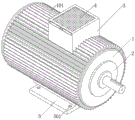
Fig. 1 is a schematic structural view of the present invention;
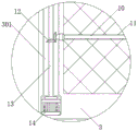
fig. 2 is a front sectional view of the present invention;
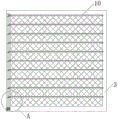
fig. 3 is a schematic view of the connection between the second rotating rod and the ventilation pipe according to the present invention;
fig. 4 is an enlarged view of a portion a in fig. 3 according to the present invention.
The reference numbers in the figures illustrate:
1. a motor housing; 101. a heat dissipating fin; 2. a motor body; 3. a vent pipe; 301. a limiting groove; 4. a filter screen; 5. a fixed base; 501. an anti-drop bolt; 6. a fan; 7. a first temperature sensor; 8. a second temperature sensor; 9. a controller; 10. a thermal insulation board; 11. a first rotating lever; 12. a bevel gear; 13. a second rotating lever; 14. a servo motor; 15. a heater.
Detailed Description
The technical solution in the embodiment of the present invention will be clearly and completely described below with reference to the accompanying drawings in the embodiment of the present invention; obviously, the described embodiments are only a part of the embodiments of the present invention, and not all embodiments, and all other embodiments obtained by those skilled in the art without any inventive work are within the scope of the present invention based on the embodiments of the present invention.
Referring to fig. 1-4, in an embodiment of the present invention, an anti-freezing permanent magnet motor includes a motor housing 1, a motor body 2 is fixedly connected to a right side of an inner wall of the motor housing 1, the right side of the motor body 2 penetrates through the motor housing 1 and extends to an outside of the motor housing 1, a ventilation pipe 3 is communicated with a top of the motor housing 1, a limiting groove 301 is formed in the ventilation pipe 3, a servo motor 14 is fixedly connected to a right side of an inner wall of the limiting groove 301, a second rotating rod 13 is fixedly connected to an output shaft of the servo motor 14, first rotating rods 11 are rotatably connected to a back side of an inner wall of the ventilation pipe 3 and are uniformly distributed, a heat insulation board 10 is fixedly connected to a surface of the first rotating rod 11, a front side of the first rotating rod 11 sequentially penetrates through the ventilation pipe 3 and the limiting groove 301 and is engaged with the, the front fixedly connected with second temperature sensor 8 of motor body 2, the interior diapire fixedly connected with controller 9 of motor housing 1, the output of controller 9 and servo motor 14's input electric connection, first temperature sensor 7 and second temperature sensor 8's output all with controller 9's input electric connection.
Referring to fig. 4, the surface of the first rotating rod 11 and the front surface of the second rotating rod 13 are fixedly connected with the bevel gears 12, the two bevel gears 12 are meshed with each other and connected, and the second rotating rod 13 can drive the plurality of bevel gears 12 to rotate through the bevel gears 12 by arranging the bevel gears 12, so that the effect of effectively reducing energy consumption is achieved.
Referring to fig. 1, a filter screen 4 is inserted into the front surface of the ventilation pipe 3, the filter screen 4 is made of a PVC material, and by arranging the filter screen 4, dust is prevented from entering the fan 6 and the motor housing 1, so that the heat dissipation efficiency of the fan 6 and the motor housing 1 is reduced, and a good dustproof effect is achieved.
Referring to fig. 2, the fan 6 is installed in the inner wall of the ventilation pipe 3 in an embedded manner, the input end of the fan 6 is electrically connected with the output end of the controller 9, and the fan 6 is arranged, so that the motor body 2 can be further cooled, and a good cooling effect is achieved.
Referring to fig. 2, the inner bottom wall of the motor housing 1 is fixedly connected with a heater 15, an input end of the heater 15 is electrically connected with an output end of the controller 9, and by arranging the heater 15, when the air temperature is lower than a certain value, the heater 15 can rapidly heat the motor body 2, so that the motor body 2 can reach a working temperature, and an effective preheating effect is achieved.
Referring to fig. 1, the fixed surface of the motor housing 1 is connected with the heat dissipation fins 101 distributed annularly, the heat dissipation fins 101 are aluminum alloy members, and by arranging the heat dissipation fins 101, when the temperature of the motor body 2 is too high, the heat conduction efficiency of the motor housing 1 can be accelerated by the heat dissipation fins 101, so that the motor body 2 can dissipate heat more quickly, and the effect of effectively improving the heat dissipation efficiency of the motor body 2 is achieved.
Referring to fig. 2, bottom fixedly connected with fixed baseplate 5 of motor housing 1, the top threaded connection of fixed baseplate 5 has evenly distributed's anti-drop bolt 501, and fixed baseplate 5 is run through and extends to the outside of fixed baseplate 5 in anti-drop bolt 501's bottom, through setting up anti-drop bolt 501, makes the staff need not worry anti-drop bolt 501 deposit the problem when using, plays the effect that reduces staff's work burden.
The utility model discloses a theory of operation is: when the first temperature sensor 7 senses that the external temperature is lower than a certain value, the first temperature sensor 7 transmits a signal to the controller 9, the controller 9 controls to turn on the servo motor 14, the servo motor 14 drives the second rotating rod 13 to rotate, the second rotating rod 13 drives the first rotating rods 11 to rotate through the bevel gear 12 at the same time, the effect of effectively reducing energy consumption is achieved, the first rotating rod 11 then drives the heat insulation board 10 to rotate, the heat insulation board 10 blocks the vent pipe 3, meanwhile, the controller 9 controls to turn on the heater 15, the heater 15 heats the motor body 2 until the second temperature sensor 8 senses that the temperature of the motor body 2 rises to a working temperature, when the first temperature sensor 7 senses that the external temperature is higher than the certain value, the first temperature sensor 7 transmits the signal to the controller 9, and the controller 9 controls to turn on the servo motor 14, the servo motor 14 drives the second rotating rod 13 to rotate, the second rotating rod 13 simultaneously drives the plurality of first rotating rods 11 to rotate through the bevel gear 12, the first rotating rods 11 further drive the heat insulation board 10 to rotate, the heat insulation board 10 opens the ventilation pipe 3 to dissipate heat, when the heat of the motor body 2 is transferred to the motor body 2, the heat dissipation fins 101 conduct the heat out, through the arrangement of the heat dissipation fins 101, when the temperature of the motor body 2 is too high, the heat dissipation fins 101 can accelerate the heat conduction efficiency of the motor shell 1, so that the motor body 2 can dissipate heat more quickly, the effect of effectively improving the heat dissipation efficiency of the motor body 2 is achieved, when the temperature sensed by the second temperature sensor 8 reaches a certain value, the second temperature sensor 8 transmits data to the controller 9, the controller 9 controls the fan 6 to be turned on, and the heat dissipation of the motor body 2 is accelerated, make motor body 2 be in a good operating condition all the time, through setting up filter screen 4, avoid the dust to get into fan 6 and motor housing 1's inside, make fan 6 and motor housing 1's radiating efficiency reduce, play good dustproof effect, through setting up anti-drop bolt 501, make the staff need not worry anti-drop bolt 501 deposit the problem when using, play the effect that reduces staff's work burden.
It should be noted that, in the above description, the motor body 2, the fan 6, the first temperature sensor 7, the second temperature sensor 8, the controller 9, the servo motor 14, and the heater 15 are all devices that are mature in application of the prior art, and a specific model can be selected according to actual needs, and meanwhile, the power supplied by the motor body 2, the fan 6, the first temperature sensor 7, the second temperature sensor 8, the controller 9, the servo motor 14, and the heater 15 can be supplied by a built-in power supply, and also can be supplied by a mains supply, and a specific power supply mode is selected according to circumstances, which is not described herein again.
The above is only a preferred embodiment of the present invention; the scope of the present invention is not limited thereto. Any person skilled in the art should also be able to cover the technical scope of the present invention by replacing or changing the technical solution and the improvement concept of the present invention with equivalents and modifications within the technical scope of the present invention.
Claims (7)
1. An anti-freezing permanent magnet motor comprises a motor shell (1), and is characterized in that: the motor comprises a motor shell (1), a motor body (2) is fixedly connected to the right side of the inner wall of the motor shell (1), the right side of the motor body (2) penetrates through the motor shell (1) and extends to the outside of the motor shell (1), the top of the motor shell (1) is communicated with a ventilation pipe (3), a limiting groove (301) is formed in the ventilation pipe (3), a servo motor (14) is fixedly connected to the right side of the inner wall of the limiting groove (301), a second rotating rod (13) is fixedly connected to an output shaft of the servo motor (14), a first rotating rod (11) which is uniformly distributed is rotatably connected to the back of the inner wall of the ventilation pipe (3), a heat insulation board (10) is fixedly connected to the surface of the first rotating rod (11), the front of the first rotating rod (11) penetrates through the ventilation pipe (3) and the limiting groove (301) in sequence and, the utility model discloses a motor, including motor housing (1), the first temperature sensor of top fixedly connected with (7) of motor housing (1), the positive fixedly connected with second temperature sensor (8) of motor body (2), the interior diapire fixedly connected with controller (9) of motor housing (1), the output of controller (9) and the input electric connection of servo motor (14), the output of first temperature sensor (7) and second temperature sensor (8) all with the input electric connection of controller (9).
2. The antifreeze permanent magnet motor of claim 1, wherein: the surface of first dwang (11) and the equal fixedly connected with conical gear (12), two in front of second dwang (13) conical gear (12) intermeshing connects.
3. The antifreeze permanent magnet motor of claim 1, wherein: the front surface of the ventilation pipe (3) is spliced with a filter screen (4), and the filter screen (4) is a PVC material component.
4. The antifreeze permanent magnet motor of claim 1, wherein: the inner wall of ventilation pipe (3) is embedded with fan (6), the input of fan (6) and the output electric connection of controller (9).
5. The antifreeze permanent magnet motor of claim 1, wherein: the inner bottom wall of the motor shell (1) is fixedly connected with a heater (15), and the input end of the heater (15) is electrically connected with the output end of the controller (9).
6. The antifreeze permanent magnet motor of claim 1, wherein: the surface of the motor shell (1) is fixedly connected with radiating fins (101) distributed annularly, and the radiating fins (101) are aluminum alloy material components.
7. The antifreeze permanent magnet motor of claim 1, wherein: the bottom fixedly connected with unable adjustment base (5) of motor housing (1), the top threaded connection of unable adjustment base (5) has evenly distributed's anti-drop bolt (501), unable adjustment base (5) are run through and the outside to unable adjustment base (5) is extended to the bottom of anti-drop bolt (501).
Priority Applications (1)
| Application Number | Priority Date | Filing Date | Title |
|---|---|---|---|
| CN202021718101.XU CN211557039U (en) | 2020-08-18 | 2020-08-18 | Anti-freezing permanent magnet motor |
Applications Claiming Priority (1)
| Application Number | Priority Date | Filing Date | Title |
|---|---|---|---|
| CN202021718101.XU CN211557039U (en) | 2020-08-18 | 2020-08-18 | Anti-freezing permanent magnet motor |
Publications (1)
| Publication Number | Publication Date |
|---|---|
| CN211557039U true CN211557039U (en) | 2020-09-22 |
Family
ID=72499275
Family Applications (1)
| Application Number | Title | Priority Date | Filing Date |
|---|---|---|---|
| CN202021718101.XU Active CN211557039U (en) | 2020-08-18 | 2020-08-18 | Anti-freezing permanent magnet motor |
Country Status (1)
| Country | Link |
|---|---|
| CN (1) | CN211557039U (en) |
-
2020
- 2020-08-18 CN CN202021718101.XU patent/CN211557039U/en active Active
Similar Documents
| Publication | Publication Date | Title |
|---|---|---|
| CN218276370U (en) | Circulating air cooling mechanism for motor heat dissipation | |
| CN218733598U (en) | Quick radiating motor casing | |
| CN211557039U (en) | Anti-freezing permanent magnet motor | |
| CN211508639U (en) | Charging cabinet with good heat dissipation effect | |
| CN216795569U (en) | Electromechanical device heat radiation structure | |
| CN206379842U (en) | A kind of high temperature resistant permanent-magnet brushless DC electric machine | |
| CN214674765U (en) | Frequency-conversion speed-regulation three-phase asynchronous motor | |
| CN112384036B (en) | High-efficient heat abstractor of electric automatization liquid cooling | |
| CN211557082U (en) | Motor with high-efficient cooling function | |
| CN210244917U (en) | Heat dissipation device of outdoor LED display screen | |
| CN209994237U (en) | Motor casing that radiating effect is good | |
| CN209445480U (en) | A kind of mini high-power warm-air drier | |
| CN217926188U (en) | Air compressor with novel structure | |
| CN214256040U (en) | High-efficiency energy-saving motor | |
| CN218417055U (en) | Auxiliary heat dissipation device of electromechanical equipment | |
| CN220291790U (en) | Motor housing easy to emit heat | |
| CN219019330U (en) | Power supply shell with good heat dissipation effect | |
| CN221009624U (en) | Heat radiation structure of energy storage power cabinet | |
| CN220510921U (en) | Liquid cooling motor | |
| CN217849159U (en) | Micro motor with automatic cooling function | |
| CN215009940U (en) | Low-speed permanent magnet synchronous servo motor with auxiliary braking function | |
| CN220793857U (en) | Box-type resistance furnace | |
| CN219107182U (en) | DC motor with cooling shell structure | |
| CN216390851U (en) | Motor controller with water-cooling structure | |
| CN216623653U (en) | LED display screen with high-efficient heat dissipation function |
Legal Events
| Date | Code | Title | Description |
|---|---|---|---|
| GR01 | Patent grant | ||
| GR01 | Patent grant | ||
| TR01 | Transfer of patent right |
Effective date of registration: 20230823 Address after: Room 214, Building 1, No. 5 Fangshui Road, Changlu Street, Jiangbei New District, Nanjing City, Jiangsu Province, 210000 Patentee after: Nanjing Jimo Control Technology Co.,Ltd. Address before: No.545, 5 / F, building 9, xingzhihui business garden, No.19 Xinghuo Road, Jiangbei new district, Nanjing, Jiangsu Province 210000 Patentee before: Nanjing KaFei Software Technology Co.,Ltd. |
|
| TR01 | Transfer of patent right |